

Abstract
Silicon carbide has excellent properties such as high hardness and decomposition temperature, but its applications are limited by its poor toughness. Here, we investigate the enhancement of SiC's toughness by compositing silicon carbide–aluminum (SiC–Al) interpenetrating phase composites (IPCs) via molecular dynamics simulations. IPCs are a class of composites consisting of two or more phases that are topologically continuous and three-dimensionally interconnected through the microstructure. The Young's modulus and ultimate strength gradually increases with an increment of the volume fraction of SiC, opposite to the fracture strain. The interface between SiC and Al affects the mechanical properties of SiC–Al IPCs. When the volume fraction of SiC is less than 0.784, the attenuation rate of ultimate strength and fracture strain decreases. The attenuation rate increases when the volume fraction of SiC is more than 0.784. There are a minimum of ultimate strength and fracture strain at the 0.784, 0.7382 and 2.8610, respectively. The hardness of SiC–Al IPCs is about 48% of SiC. The change of SiC–Al IPCs hardness is more stable than that of SiC in the later stage of the nanoindentation test.
Export citation and abstract BibTeX RIS
1. Introduction
Composites are increasingly used in the aerospace, automotive, and biomedical industries [1–4]. A composite has superior performance. These properties include improved thermal conductivity, abrasion resistance, tribology, creep resistance, dimensional stability, and exceptionally good stiffness [5]. Unlike traditional discrete-phase reinforced composites, interpenetrating phase composites (IPCs) are a class of composites consisting of two or more phases that are topologically continuous and three-dimensionally interconnected through the microstructure. This interconnectivity is such that if one phase is removed, the remaining phase or phases will still maintain structural integrity and load bearing capability [6].
There are a number of studies on composites containing silicon carbide or aluminum. Silicon carbide [7, 8] is used as a reinforcing material. Aluminum, titanium and magnesium are the most common matrix materials [9, 10]. Reddy et al [11] studied the mechanical properties of aluminum metal matrix composites (MMC), which were produced by the stir casting technique. The properties of tensile, flexural, hardness and impact tests of the material were superior to that of pure aluminum. In the study of Srivastava et al [12], the silicon carbide-aluminum MMC were obtained by friction stir processing (FSP). The effects of multi-pass FSP and cooling environment on microstructural evolution and mechanical properties were investigated. It was also found that the heat input, heat dissipation and post processing cooling during FSP affect the grain structure, microstructure evolution and mechanical properties of the silicon carbide–aluminum matrix composite. Silicon carbide is widely used as a reinforcing material [13, 14]. Alaneme et al [15] produced hybrid composites via a two-step stir casting technique, and studied the effect of mixing ratio of peanut shell ash (GSA) and silicon carbide on the mechanical properties of aluminum matrix composites. The microstructure, hardness, tensile and fracture toughness tests were performed to appraise the mechanical properties of the composites. It can be concluded that the fracture toughness of the composites increased with the increasing of the proportion of GSA. In addition, silicon carbide-aluminum composites can be prepared by the pressureless infiltration technique [1] and vacuum-pressure infiltration [16]. Based on experimental method, the composite of silicon carbide and aluminum have been obtained. However, the specific combination of silicon carbide and aluminum in the composite is not visually observed. The relationship and interaction between the atoms of the composite can be more clearly observed by molecular dynamics simulation.
Gu et al [17] study the effects of SiC-β nanoparticle on the mechanical properties and interfacial structure of aluminum matrix composites by MD simulation. Compared with the results of finite element analysis in other literature. SiC-β nanoparticles help to enhance the Young's modulus and yield stress of aluminum matrix composites. Based on MD simulation and Hugoniostat method, the effects of initial hydrostatic pressure and cooling rate of material on the mechanical properties of silicon carbide–aluminum composites were studied. It is concluded that the mechanical properties of the material were improved with impact pressure increasing, and an appropriate cooling rate helps to increase the bonding strength of the nanoparticles [18].
IPCs include metal-metal IPCs and metal-ceramic IPCs, such as stainless steel-bronze IPCs [19], Al–Al2O3 IPCs [20] and so on. The preparation methods of IPCs mainly include oriented metal oxidation method, extrusion casting method, gas pressure assisted infiltration method, self-propagating high-temperature synthesis method [21]. These methods are mainly used to prepare IPCS of macrostructure. At present, there are few preparation methods of interpenetrating phase nano-composite. Zhang et al obtained Cu–Al2O3 interpenetrating phase nano-composite at room temperature by electrochemical metal infiltration. The Vickers indentation test was carried out on the material. The hardness was twice as high as that of the nano-porous Al2O3 which was not filled with Cu [22]. The elasticity, strength and thermal expansion properties of IPCs were studied by finite element analysis. Compared with other composite, the elasticity, strength and thermal expansion properties of IPCs had been improved [21]. Compared with IPCs containing SiC phase, the research of IPCs containing Al phase are more, such as Al−Al2O3 IPCs [20], Al−Si3N4 IPCs [23] and so on.
There are few studies of SiC–Al IPCs. Li et al [24] prepared SiC–Al IPCs by gas pressure infiltration method and studied its thermophysical properties. It was found that SiC–Al have higher thermal conductivity and lower thermal expansion coefficient than SiC particle reinforced aluminum matrix composites at the same SiC volume fraction.
In this study, the MD method was used to simulate the SiC–Al IPCs. The volume fraction of silicon carbide, the interfacial properties of aluminum–silicon carbide and the effect of crack on the tensile mechanical properties of the material were studied. The hardness of the aluminum-silicon carbide IPCs was measured.
2. Materials and methods
In this work, we employ MD simulation to construct periodic IPCs consisting of silicon carbide and aluminum. The model of SiC–Al IPCs is shown in figure 1. The preparation for the initial configurations of the atomic SiC–Al model consists of three steps [25]. First, crystal model of pure aluminum is built. Next, a silicon carbide crystal model is established. Finally, according to the size required for the simulation, the pure aluminum and silicon carbide crystal models are respectively sheared, and the obtained pure aluminum and silicon carbide crystal models are spliced. A silicon carbide–aluminum model of 20a × 20a × 20a is built (a is a lattice constant of SiC). The size of the silicon carbide frame is L1 × L1 × L1, and the size of the aluminum core is L2 × L2 × L2. MD method is widely used in many fields [26, 27]. All studies in this study are performed by MD simulations based on LAMMPS package [28–30]. The post-processing and results visualization are performed by OVITO [31].
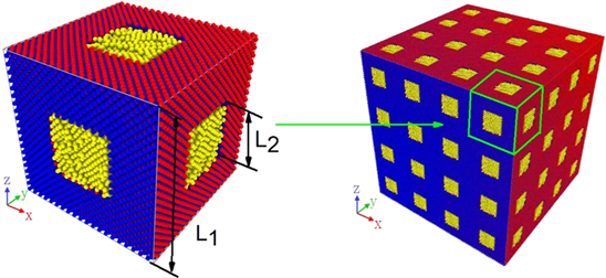
Figure 1. The model of SiC–Al IPCs,  -C,
-C,  -Si,
-Si,  -Al. The size of the silicon carbide frame is L1 × L1 × L1, and the size of the aluminum core is L2 × L2 × L2.
Download figure:
Standard image High-resolution imageIn all simulations, periodic boundary conditions along x and y direction are used. Fixed boundary conditions are used in the z direction when performing nanoindentation testing on the model. In other simulation tests, periodic boundary conditions are used in the z direction. The time step is 0.1 fs. To avoid the thermal and pressure effect, the temperature and pressure of simulation are controlled by the Nose–Hoover thermostat and barostat. The NPT ensemble was performed for the simulations, including the relax stage and tensile stage. The external pressure was zero at the relax stage. But at the tensile stage, external pressure in tensile direction was not controlled, since the stress was calculated by the pressure in the tensile direction. In the nanoindentation simulation, the NVT ensemble was used throughout the system. In addition, the engineering strain rate 109 s−1 is given, and the simulated time is strain rate timing tensile strain. The trajectories of relax stage and tensile stage were recorded every 1000 timesteps. And the data of stress–strain curve was output every 500 timesteps.
The interaction of atoms in SiC is described by tersoff potential. The interaction between Al atoms is described by embedded atom method potential [10, 32]. The interaction between atoms of C, Si and Al is described by Morse potential with atoms cutffs of 2.5 Å. Based on conjugate gradient method, the energy minimization is carried out in all simulations
3. Results and discussion
3.1. Effect of volume fraction on tensile mechanical properties
This section studies the effect of the silicon carbide volume fraction (SiC–Vf) on the mechanical properties of silicon carbide–aluminum structures. The mechanical properties of the material were judged by parameters such as ultimate strength, fracture strain and Young's modulus. Ultimate strength is the maximum stress of the material at break and fracture strain is the strain at the time of the material failure. Young's modulus is the ratio of stress to strain in the linear range. The parameter of L1 is 20a. The a is a lattice constant of SiC, which is 4.348 Å [33]. The value of L2/L1 is 0.2, 0.3, 0.4, 0.5, and 0.6, respectively. The volume fraction (Vf) of SiC–Al is calculated, 0.896, 0.784, 0.648, 0.5, 0.352, respectively [18, 34–37]. Based on the volume fraction, SiC–Al models are established.
The stress–strain curve of the SiC–Al with different SiC–Vf is shown in figure 2(a). The change of ultimate strength, fracture strain and Young's modulus are shown in figure 2(b). It can be seen from the figure 2 that ultimate strength and Young's modulus of SiC–Al increases with the volume fraction increasing, but fracture strain decreases [34]. The strength and Young's modulus of SiC are much higher than that of Al. When the Vf of SiC increases, the strength and Young's modulus of the silicon carbide aluminum increase. With the decreasing of SiC–Vf, Al becomes the dominant material in the composite. The plasticity of Al is better than that of SiC. The fracture strain of the silicon carbide aluminum structure gradually increases with the decreasing of SiC–Vf. It can be concluded from figure 2 that the toughness of silicon carbide aluminum is gradually increased with the increase of aluminum composition.
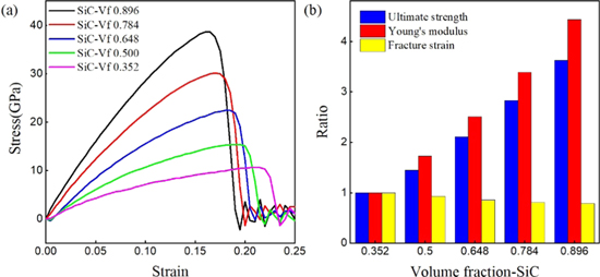
Figure 2. (a) Stress–strain curves of SiC–Al in different Vf of SiC. (b) The change of ultimate strength, fracture strain and Young's modulus in different Vf of SiC.
Download figure:
Standard image High-resolution image3.2. Effect of interface properties on tensile mechanical properties
Interface separation of Al and SiC phases occurs when the SiC–Al structure are stretched [37]. Interface separation affects the mechanical properties of SiC–Al structure. In order to study the relationship between interface and mechanical properties of SiC–Al structure, we select the SiC–Al model with silicon carbide volume fraction of 0.648 as the research object. The model is stretched along the direction of z-axis. The stress and separation width of SiC–Al as a function of strain are plotted in figure 3.
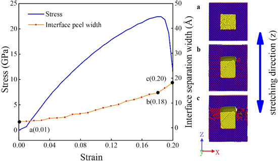
Figure 3. Stress–strain curve, interface separation width curve and fracture morphology of SiC–Al at 0.648 of SiC–Vf.  -C,
-C,  -Si,
-Si,  -Al. The model is stretched along the direction of z direction.
Download figure:
Standard image High-resolution imageIt can be seen from figure 3 that the separation width continues to increase with the strain increasing. The increase of separation width can be roughly divided into two parts. When tensile strain is less than 0.18 (point b), small peel between the two phases is detected. The slope of the curve between point a and b is approximately 29 Å. In this region, the slope of the separation width is small, implying that the interfacial properties of the SiC–Al IPCs are better. When tensile strain is more than 0.18 (between point b and c), the separation width is significantly increased. When the stress reaches a maximum value, a jump of curve occurs at point b. The slope of the curve between point b and c is approximately 125 Å. Cracks are generated in the SiC–Al composites, and the interaction of interface between SiC and Al gradually decrease. The stress sharply declines and the material failures. When the material failures, the SiC frame instead of Al is broken as shown in figure 3. Within the whole stretching process, the interfacial properties between the SiC and Al is best in the range of point a to b. The presence of the interface hinders the crack propagation. In the region between point b and c, the interaction between SiC and Al is negligible. Cracks are generated in SiC frame and rapidly expand, eventually leading to fracture of structure. Through the above analysis, the interface properties of SiC–Al have an important influence on the mechanical properties.
3.3. Effect of crack on tensile mechanical properties
Cracks are one of the main defects affecting the properties of materials [38]. In this section, two contents were studied. First, the effects of cracks size on the mechanical properties of SiC–Al with different SiC–Vf are investigated. We choose a model with a silicon carbide volume fraction of 0.648 as the research object. Second, the effects of cracks with different size on the mechanical properties of SiC–Al are investigated. A rectangular crack parallel to the x–y plane is constructed by deleting atoms on the SiC skeleton. The height of the crack is 3 Å. The size of cracks is 12.5435 Å along the y directions. The size of the x direction is selected to be 0 Å, 6.5435 Å, 12.5435 Å, 18.5435 Å, 24.5435 Å, 48.5435 Å, and 72.5435 Å, respectively. The location of crack is in the middle of the z direction of the model. When studying the effect of volume fraction, we choose a model with a crack size of 12.5435 Å.
Figure 4(a) is a model of silicon carbide aluminum with cracks. In figure 4(b), the attenuation rate of ultimate strength and fracture strain of SiC–Al IPCs are positive value. It indicates that the existence of cracks reduces the ultimate strength and fracture strain. When the volume fraction of SiC is less than 0.784, the attenuation rate of ultimate strength and fracture strain decrease. The attenuation rate increase when the volume fraction of SiC is more than 0.784. There are a minimum of ultimate strength and fracture strain at the 0.784, 0.7382 and 2.8610, respectively. When the volume fraction of silicon carbide is 0 or 1, the model only contains the aluminum phase or silicon carbide phase. The rapid expansion of the crack leads to the fracture of Al or SiC. Compared with the Al or SiC model without crack, the crack propagation time of the model is advanced, so both ultimate strength and fracture strain are reduced. The strength and toughness of aluminum surpass that of silicon carbide, so the attenuation rate of SiC Vf-0 is higher than that of Vf-1. When the volume fraction of SiC is 0.784, the attenuation rate of ultimate strength and fracture strain both reach a minimum value. It indicates that the crack has the smallest effect on the tensile properties of SiC–Al. At this volume fraction, the effect of cracks on silicon carbide aluminum is minimal, and the combination of silicon carbide and aluminum is the best. In summary, the interface hinders the expansion of the internal crack of the silicon carbide aluminum, so that ultimate strength and fracture strain are less than that of pure aluminum and silicon carbide.
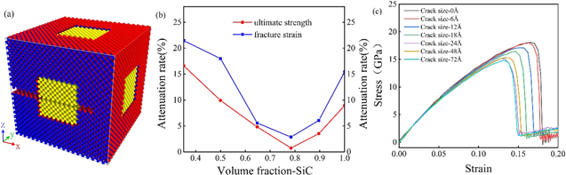
Figure 4. (a) The model of silicon carbide aluminum with crack size of 72.5435 Å. (b) The curve of strength and strain attenuation rate with different silicon carbide volume fraction of SiC–Al. (c) The stress–strain curve of SiC–Al with different size crack.
Download figure:
Standard image High-resolution imageIt can be seen from figure 4(c) that the ultimate strength and fracture strain of the structure are both reduced with the size of crack increases. The model with cracks is stretched along the z direction. Due to periodic boundary conditions, cracks are also gradually formed on the other three edges parallel to the z-axis, and the original cracks begin to expand. The crack propagation time of the model is advanced. The larger the crack size, the more easily the SiC–Al structure breaks. It can be observed from figure 4(c) that the difference in Young's modulus of models is not obvious.
3.4. Nanoindentation simulations
The hardness measured by nanoindentation simulations is an important parameter to evaluate the processing properties of the material [39]. Nanoindentation has become one of the important processing methods in nanoscale field [40–43]. Simulation of nanoindentation is carried out to study SiC–Al IPCs properties.
The SiC–Al IPCs model with SiC Vf of 0.648 is constructed. The model of nanoindentation simulation is shown in figure 5(a). The size of the SiC–Al model is 40a × 40a × 40a. The a is a lattice constant of SiC, which is 4.348 Å. Periodic boundary conditions along x and y direction are used. Fixed boundary conditions are used in the z direction. To simulate the removal of oxide layers in an actual nanoindentation experiment, atoms with thickness of 1.4165 Å in top layer were removed and atoms with thickness of 1.5435 Å in bottom layer were removed. Fixed all atoms with thickness of 1 Å in bottom layer. The SiC–Al model was subjected to a nanoindentation experiment using a spherical indenter with a radius of 80 Å. The indenter is located above the center of the model and is pressed down along the z-axis. When the indenter is in contact with the top layer of the model. The indenter speed of the 0.05 Å ps−1 is given to press down the model, and the total depression is 30 Å. The nanoindentation test is also carried out in SiC model.

Figure 5. (a) The model of nanoindentation simulations. The curve of (b) load-depressing depth and (c) hardness-depressing depth of SiC and SiC–Al. The SiC–Al model was subjected to a nanoindentation experiment using a spherical indenter with a radius of 80 Å. The indenter is located above the center of the model and is pressed down along the z-axis. When the indenter is in contact with the top layer of the model. The indenter speed of the 0.05 Å ps−1 is given to press down the model, and the total depression is 30 Å.
Download figure:
Standard image High-resolution image
The curve of load-depressing depth and hardness-depressing depth of SiC and SiC–Al are shown in figure 5. In figure 5, the load and hardness of SiC–Al IPCs is less than that of SiC in the nanoindentation simulation. Due to the low hardness of SiC–Al, the processing properties of SiC–Al IPCs are better than that of SiC.
The change of load is shown in figure 5(b). It can be found that load and depression depth show positive correlation. The load of SiC–Al and SiC curves are similar. But the load of SiC is higher than that of SiC–Al. At the initial moment, the atoms collide and separate from the indenter, causing load slight fluctuation. As the indenter is gradually pressed, the contact area becomes a major influencing factor of the load. As the contact area increases, the load increases. For silicon carbide aluminum, the atoms of outer layer of the model are pressed out of the surface at the last moment. The load growth slowly and the load tends to be stable.
In figure 5(c), the hardness of SiC is higher than that of SiC–Al. The hardness of the SiC–Al increases at the initial moment and tends to be stable. The indenter gradually contacts the SiC frame with the increasing of the depth of the pressing. The compression of the SiC–Al makes the structure more densely. Hardness remains stable due to the destruction of the original structure and the formation of a new relatively stable structure. For the model of SiC, the hardness of SiC rapidly increases in the early stage due to the density increases. Then, the hardness tends to be stable with the depressing depth increasing. Finally, a new relatively stable structure is formed due to the destruction of the original structure. The hardness of silicon carbide tends to be stable.
4. Conclusion
In this study, the model of SiC–Al IPCs is constructed based on MD simulation. We studied the mechanical properties of silicon carbide aluminum, including tensile mechanical properties and nanoindentation properties. The volume fraction of silicon carbide, the interfacial properties of aluminum-silicon carbide and the effect of crack on the tensile mechanical properties of the material were studied. The Young's modulus and ultimate strength of SiC–Al IPCs gradually increases with the volume fraction of SiC increasing, but the fracture strain decreases. The toughness of SiC–Al IPCs is gradually increased with the increase of aluminum composition. The interface between SiC and Al affects the mechanical properties of SiC–Al IPCs. The hardness of SiC–Al IPCs is smaller than that of SiC. The hardness of SiC–Al IPCs is more stable than that of SiC in the later stage of nanoindentation test. The attenuation rate of ultimate strength and fracture strain of SiC–Al IPCs decrease first and then increase with the increases of SiC volume fraction. The attenuation rate of ultimate strength and fracture strain of SiC–Al IPCs reach the minimum when the volume fraction of SiC is 0.784. The ductility and processability of SiC–Al IPCs are improved compared to silicon carbide. The strength and hardness of SiC–Al IPCs are improved compared to aluminum. Comparing the several conditions we selected, it can be concluded that the SiC–Al IPCs has better performance when the volume fraction of silicon carbide is 0.748.
Acknowledgments
This work is supported by National Natural Science Foundation of China (21703007 and 51702332) and Fundamental Research Funds for the Central Universities (FRF-GF-18-011B).
Disclosure statement
No potential conflict of interest was reported by the authors.