
Abstract
Among two-dimensional (2D) layered van der Waals materials, ferromagnetic 2D materials can be useful for compact low-power spintronic applications. One promising candidate material is Fe3GeTe2 (FGT), which has a strong perpendicular magnetic anisotropy and relatively high Curie temperature. In this study, we confirmed that an oxide layer (O-FGT) naturally forms on top of exfoliated FGT and that an antiferromagnetic coupling (AFC) exists between FGT and O-FGT layers. From a first-principles calculation, oxide formation at the interface of each layer induces an AFC between the layers. An AFC causes a tailed hysteresis loop, where two-magnetization reversal curves are included, and a negative remanence magnetization at a certain temperature range.
Export citation and abstract BibTeX RIS

Original content from this work may be used under the terms of the Creative Commons Attribution 3.0 licence. Any further distribution of this work must maintain attribution to the author(s) and the title of the work, journal citation and DOI.
Two-dimensional (2D) ferromagnetic (FM) materials with van der Waals (vdW) interactions between the adjacent layers have drawn lots of attention because of their simultaneous perfect crystallinity, charge transport characteristics, and spin dynamics. Using magnetic materials with a perpendicular anisotropy is an attractive method for spintronic devices because of the low energy consumption and high speed of the switching process compared with typical electron-based semiconductor devices [1, 2]. As the magnetic properties of vdW materials can be manipulated by the thickness [3–5], atomic composition [6, 7], gating bias [8, 9], etc., FM vdW compounds such as Fe3GeTe2 (FGT) [10–12], CrI3 [5, 13, 14], and Cr2Ge2Te6 [4, 15, 16] have drawn a great attention. Bulk-FGT has a hard magnetic property with a perpendicular easy-axis and a high Curie temperature of about 200 K [17, 18]. In particular, FGT has been theoretically predicted to exhibit FM properties down to the monolayer regime [19]. Recently, research on nano-FGT has been conducted by Tan [3] and Fei [20] with the exfoliation method and by Liu [21] with nano-FGT grown by molecular beam epitaxy. They show a change in Curie temperature with variation in thickness.
In this study, we demonstrate the existence of an antiferromagnetic coupling (AFC) between nanoflake FGT layers mediated by oxidation by using anomalous Hall measurements. The existence of AFC in bulk-FGT was introduced by Yi [10] in 2016; however, there is no observation of this effect in recent studies of nano-FGT [3, 8]. We assumed that the origin of AFC in bulk-FGT is an extrinsic effect. This is because when the transition metal is oxidized, the antiferromagnetic property is more common by the super-exchange effect and the spin–orbit coupling (SOC) [22, 23] such as CaXO (X = Mn, Cr) [24, 25] and XO (X = 3d ferromagnetic elements) [26]. Therefore, we tried to realize antiferromagnetic characteristics by oxidation of FGT. Several 2D materials, such as BP [27] and Bi2Se3 [28] are unstable under ambient conditions. FGT is also unstable in air, so that a glovebox [28] or h-BN encapsulation [29] are needed to protect it from oxidation. For our experiments, we fabricated an exfoliated 30 and 40 nm thick FGT films with Hall-bar geometry. After fabricating the devices, we oxidized it at ambient condition for several weeks to make an oxide layer (O-FGT) without a contact problem. The sample structure was SiO2/FGT/O-FGT. In our experiments, we observed the negative remanence magnetization (NRM), which was a unique feature of AFC in FM bilayers. Since the ferromagnet has remanent magnetization at zero external magnetic field, the NRM is expressed when two different FM layers with different FM characteristics are in opposite directions, which means that there is an AFC [30–33].
The bulk-FGT grown by the multizone chemical vapor transport method was a single crystal of about 1 mm3 (upper inset of figure 1(a)) and had perfect crystallinity and magnetic anisotropy along the c-axis of the film. Figure 1(a) is a transmission electron microscopy (TEM) image of bulk-FGT with a native oxide layer. For the pure FGT layer shown below (dark region), the formation of the vdW layer was confirmed through crystallinity and fast Fourier transform (FFT) results (lower inset of figure 1(a)). The FFT results show diffraction patterns from the lattice structure. The lattice parameters a and c calculated by FFT were 3.48 and 16.38 Å, respectively, which are similar to the previously reported values [7, 34]. Bulk-FGT has the composition of Fe3:Ge1:Te2.2 and the crystal axis in both the energy dispersive spectrometry and x-ray diffraction methods was the c-axis. (See the supplementary information 1–3, available online at stacks.iop.org/NANO/30/245701/mmedia.) Naturally formed O-FGT has an amorphous phase including a polycrystalline structure (see the bright region of figure 1(a)). As found in a recent study [3, 8], FGT is a single crystal and has the magnetization reversal characteristics of a single domain [3], which has a good squareness of hysteresis curves with a magnetic remanence close to unity. However, since O-FGT is not a single crystal, and magnetization reversal of O-FGT acts in a multidomain regime. This feature may induce a complex magnetization reversal, unlike the case of FGT.
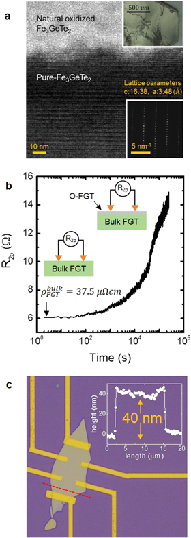
Figure 1. (a) A cross-sectional TEM image of bulk-FGT (upper inset of (a)). O-FGT formed naturally on top of FGT. The lattice parameters a and c of bulk-FGT from the FFT result are 3.48 and 16.38 Å, respectively (lower inset of (a)). (b) Resistance change of bulk-FGT with time. Inset figures indicate the formation of O-FGT during the natural oxidation process. (c) An optical microscope image of 40 nm thick FGT device. The thickness FGT obtained using by atomic force microscopy is shown in the inset of (c).
Download figure:
Standard image High-resolution imageThe formation of native O-FGT can be confirmed by resistance measurements. Figure 1(b) shows the two-probe resistance change over time. The resistance was measured immediately after the surface layer was removed using the exfoliation method. The surface of FGT changes over time to O-FGT by binding with oxygen in the atmosphere, causing a change in the overall resistance of the sample. The inset of figure 1(b) is a schematic of the formation of O-FGT over time. The bulk resistivity of FGT was obtained as 37.5 μΩ cm.
In order to confirm the effect of O-FGT, we fabricated FGT devices, and measured the change of magnetic properties by forming a natural O-FGT several weeks. Figure 1(c) shows the optical microscope image of 40 nm thick FGT device. The thickness of FGT obtained by atomic force microscopy is shown in the inset of figure 1(c).
Figures 2(a)–(c) show the results of the temperature dependent anomalous Hall effect (AHE) of FGT device. When a perpendicular magnetic field is applied, the  of the sample has the following relationship

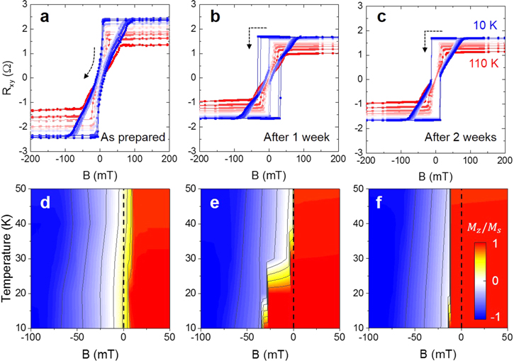
Figure 2. The anomalous Hall effect (AHE) measurement at various temperatures from 10 to 110 K with (a) as prepared device, (b) natural oxidized during 1 week, and (c) 2 weeks. (d)–(f) The contour map of normallized magnetization of each device. Note that the type of switching changes from (d) continuous to (e) and (f) abrupt switching due to the oxidation time.
Download figure:
Standard image High-resolution imageThe first term is the ordinary Hall effect proportional to the Lorentz force because of the perpendicular magnetic field  and the second term is the AHE caused by the perpendicular magnetic moment
  of the sample. Because the spontaneous magnetization of FM materials is large enough, the ordinary Hall effect can be ignored in this case. Thus,
  depends on the magnitude of
  In addition, it can be seen that there is no slope change with varying the magnetic field in figures 2(a)–(c). We measured a hysteresis curves at various temperatures after fabricating the device (figure 2(a)), and then confirmed the effect of oxidation by re-measuring at the intervals of several weeks (figures 2(b) and (c)). The hysteresis curves show the FGT has perpendicular magnetic anisotropy, and the multi-domain magnetization reversal. After natural oxide formation, however, the shape of the magnetization reversal at low temperature changed from the continuous switching to abrupt switching (see the dotted arrow in figures 2(a)–(c)). In particular, it can be seen that the magnetization switching occurs in two steps as the magnetic field sweeps from positive to negative. Figures 2(d)–(f) is the contour map of each experiments (figures 2(a)–(c)) with normalization of magnetization, respectively. When we measured a FGT with an as prepared condition (figures 2(d)), the magnetization is inverted from upward (red zone) to downward (blue zone) before the external magnetic field becomes zero, and continuous switching occurs. On the other hand, when the natural oxidation time increases, an abrupt magnetization reversal appears after zero magnetic field (figure 2(e)), and this type of swithing region gradually increases with the oxidation time (figure 2(f)).
Figure 3(a) shows the results of the AHE measurement of the 30 nm thick FGT/O-FGT device. At 2 K, the AHE measurement shows the value of  to be 2.5 Ω and a good squareness of the hysteresis loop. As the temperature gradually increases from 2 to 220 K, the perpendicular magnetic anisotropy of the FGT/O-FGT changes, resulting in a change in the magnetic hysteresis curve. The coercive field
  saturation field
  and modulated magnetic remanence
  obtained from figure 3(a) are shown in figures 3(b)–(d), respectively.
  and
and  are inversely proportional to the temperature because the magnetic anisotropy decreases with increasing temperature. The result of the AHE measurement has two peculiarities. First, there is a tail of hysteresis curves in all FM temperature ranges. It gradually decreases with increasing temperature (figure 3(c)). To understand this effect in detail, the results of AHE at 50 K are shown in figure 3(e). The solid line is the result of the normalized
  at 50 K. The two dotted lines are the deconvoluted hysteresis curves from the experimental data. This is a phenomenon in which the soft and hard FM layers (Loops 1 and 2, respectively) are independently magnetized and are not connected to each other. In other words, Loops 1 and 2 represent the magnetic hysteresis curves of pure FGT and O-FGT, respectively. Second, a NRM is observed from 90 K to
  Figure 3(d) shows the remanence magnetization for each temperature divided by the value at 2 K. It has a maximum value at around 50 K and shows the NRM at 90 K. As the NRM is only observed in systems that include AFC [30–32], this is evidence for the presence of AFC at the interface between FGT and O-FGT. As the temperature gradually increases, the FM ordering weakens, thus magnetic anisotropy decreases. The temperature dependence of magnetic anisotropy is shown in the supplementary information, note 4.
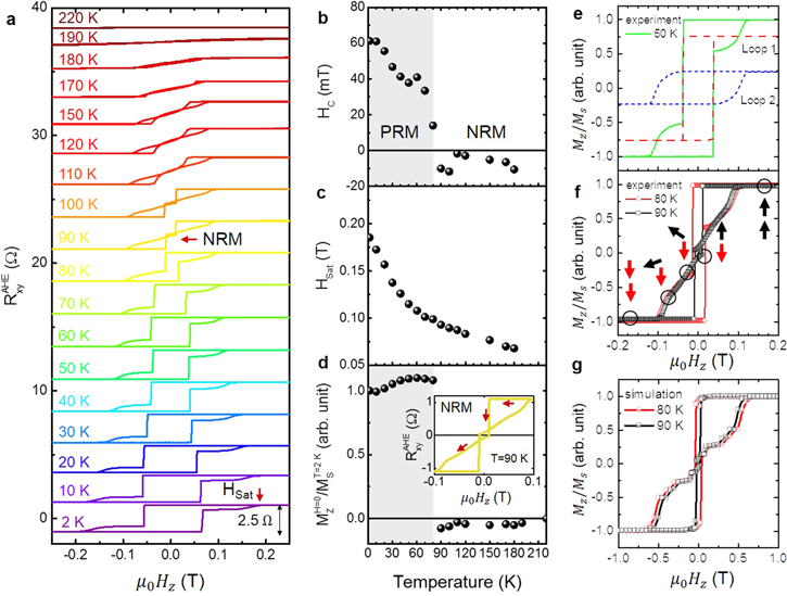
Figure 3. (a)  versus
  curves of the FGT/O-FGT device with varying temperature from 2 to 220 K. Perpendicular anisotropy appears from Tc. Note that two special points were found, which are indicated in (a) with red arrows; one is the tail of the hysteresis curve and the other is the NRM. The temperature dependence of (b)
  (c)
(c)  and (d)
  The boundary temperature of PRM and NRM is 90 K; (e) normalized
  of the hysteresis loop at 50 K and deconvoluted curves (Loops 1 and 2). The reason for the hysteresis tail is that there exist two FM structures in the system. In our case, Loops 1 and 2 indicate an FGT and O-FGT, respectively. The (f) experimental and (g) simulated results of NRM.
Download figure:
Standard image High-resolution imageTo determine the role of AFC in NRM phenomena in FGT/O-FGT structures, we carried out a micromagnetic simulation using by mumax3 [35]. A certain antiferromagnetic exchange stiffness constant was used between the two magnetic layers and the magnetic anisotropy of each layer was changed according to the temperature. The result of AHE and simulated curves at the boundary temperature of NRM are shown in figures 3(f) and (g). The details of our simulation are described in the Methods section. We fixed the fitting parameter of exchange coupling in each layer and the AFC strength at the interface of FGT/O-FGT. The NRM at 90 K changes to positive remanence magnetization at 80 K, after increasing the magnetic anisotropy of each layer. The hysteresis curves of figure 3(f) show the magnetization switching process of two magnetic layers. The changes due to anisotropy in the micromagnetic simulations were very similar to the experimental ones (figure 3(g)).
To verify the existence of oxide for the AFC, we used a first-principles calculation for the configuration of the oxide formation. The details of our calculations are described in the Methods section. Figure 4(a) shows a schematic illustration of the pristine FGT monolayer structure. We performed a lattice relaxation for the pristine monolayer and found the optimized lattice constants of a = b = 4.05 Å. Indeed, the pristine FGT shows an FM spin ground state [10]. In this structure, we obtained a total magnetic moment of 6.3 μB per unit cell. In figure 4(b), the local magnetic moment of each Fe atom is presented. The Fe atom in the same layer with Ge had a relatively smaller magnetic moment than the other two Fe atoms and we found no meaningful spin magnetic moments in the Ge and Te atoms. As our device was naturally oxidized in the atmosphere, we also explored the effect of O adsorption on the magnetic property. Three different oxygen adsorption sites were investigated, namely, Fe-top, Ge-top, and Te-top and they are indicated respectively by A, B, and C in figure 4(a). In each position, we performed structure relaxation. Note that the O atom moved toward the bridge between Fe and Te, even when we initially placed the O atom on top of Ge. The most stable among these three configurations was found in bridge adsorption and table 1 shows the total energy difference. Figures 4(c) and (d) shows the most stable relaxed structure along with the local magnetic moment of each Fe atom. The lattice constants have expanded from a = b = 4.05 Å to a = b = 4.17 Å after O adsorption. Nonetheless, no significant change in the Fe magnetic moment was found.

Figure 4. Geometric structure: (a) top view of FGT with possible oxygen adsorption sites; (b) side view of pristine FGT with the calculated magnetic moments; (c) top view of the relaxed structure of O-FGT; (d) side view of O-FGT with the calculated magnetic moments; and (e) and (f) are the possible O-FGT bilayer structures, along with the layer-to-layer spin configurations. The violet, green, yellow, and red balls represent Fe, Ge, Te, and O atoms, respectively.
Download figure:
Standard image High-resolution image
Table 1. Energy difference (in meV) between the relaxed structures of the oxidized system, initiated from three sites shown in figure 3(a). Site B is taken as zero as reference.
| Sights | Fe-top (A) | Ge-top (B)→ bridge | Te-top (C) |
|---|---|---|---|
| Energy (meV) | 9 | 0 | 1022 |
Using this information, we investigated the magnetic property of the bilayer system. Here, we considered the two staking configurations shown in figures 4(e), (f) and the structure shown in figure 4(f) was more stable with an energy difference of 15 meV. To find a magnetic ground state in the bilayer system, we performed a total energy calculation for non-magnetic (NM), FM and antiferromagnetic (~(AFM) states) with a full potential-based Wien2k code [36]. Without SOC, the energy difference between NM and AFM (ENM–EAFM) was 1.5 eV while the energy difference between FM and AFM (EFM–f EAFM) was only 0.5 meV. However, it was increased to 10 meV after including the SOC effect. This indicates that the SOC plays an essential role in the layer-to-layer magnetic exchange in oxidized system. Since the interlayer distance is rather large to have direct Fe–Fe coupling between two layer, the magnetic information in one layer is mediated to the next layer by indirect route. We found that the oxygen p-orbital negatively polarized with respect to the Fe atom. This negative polarization is mediated to the Ge atom in the neighboring layer and results in the AFM state.
In conclusion, vdW FGT is a metallic ferromagnet with a strong perpendicular magnetic anisotropy and a relatively high Curie temperature. An exfoliated FGT easily forms an O-FGT in ambient condition. Although the FGT/O-FGT bilayer has complex ferromagnetism and cannot be easily understood, AFC exists at the interface of FGT/O-FGT. The presence of AFC in the FGT/O-FGT bilayer was confirmed by the tail of the hysteresis curves and the appearance of NRM. Our experimental results were confirmed by AHE measurements with several temperature and micromagnetic simulations. Using a first-principles calculation, we have shown that with the SOC, the inclusion of O atoms in between the layers induces an AFC.
Methods
Micromagnetic simulations
We performed micromagnetic simulations in FGT/O-FGT structures to confirm the NRM through the magnetic hysteresis loop, using micromagnetic simulation program mumax3 [35] based on the Landau–Lifshitz torque considering the damping term. To find the origin of NRM as temperature dominant, we fixed some magnetic parameters of the FGT/O-FGT systems. When the temperature is changed from 80 to 90 K, the saturation magnetization  and exchange stiffness constant
  are fixed and magnetic uniaxial anisotropy
  is only changed. In this study, we focus on the relation of
  of FGT and O-FGT layers and AFC between them. A cell size is 0.5 nm × 0.5 nm × 0.5 nm and a total volume is 8 nm × 8 nm × 18 nm (FGT (9 nm)/O-FGT (9 nm) structure). Magnetic material parameters are
  and
and  For FGT,
  of 150
  at 80 K is changed to 30
  at 90 K, and for O-FGT,
  of 400
  at 80 K is changed to 350
  at 90 K. At both temperatures, hysteresis loops are simulated with z-axis magnetic field variations and with consideration for AFC
  between FGT and O-FGT layers.
Ab initio calculations
We first performed the structure relaxation using the Vienna Ab initio simulation package (VASP) [37–39]. Valence electrons were treated explicitly by plane-wave method and their interactions with ionic cores were described by projected augmented plane-wave pseudopotentials [40, 41]. The plane-wave energy cut-off of 600 eV is used. All atomic positions are relaxed until the residual forces on the atoms were smaller than 0.02 eV Å−1 and the energy convergence reached up to 10−5 eV/atom using the conjugate gradient method. The DFT-D3 method of Grimme with Becke–Jonson damping was employed for vdW corrections in the bilayer systems [42]. We imposed a vacuum region of 15 Å in the z direction for all these calculations in order to avoid an artifical interaction from neighboring unit cell.
Acknowledgments
This work was supported by the Future Materials Discovery Program through the National Research Foundation of Korea (No. 2015M3D1A1070467, 2016R1A2B4012931) and a National Research Council of Science & Technology (NST) grant (No. CAP-16-01-KIST) from the Ministry of Science, ICT and Future Planning (MSIP). Part of this work is also supported by the Basic Science Research Program through the National Research Foundation of Korea (NRF) funded by the Ministry of Science, ICT and Future Planning (2016R1A2B4006406).