

Abstract
We have designed, fabricated and tested a robust superconducting ratchet device based on topologically frustrated spin ice nanomagnets. The device is made of a magnetic Co honeycomb array embedded in a superconducting Nb film. This device is based on three simple mechanisms: (i) the topology of the Co honeycomb array frustrates in-plane magnetic configurations in the array yielding a distribution of magnetic charges which can be ordered or disordered with in-plane magnetic fields, following spin ice rules; (ii) the local vertex magnetization, which consists of a magnetic half vortex with two charged magnetic Néel walls; (iii) the interaction between superconducting vortices and the asymmetric potentials provided by the Néel walls. The combination of these elements leads to a superconducting ratchet effect. Thus, superconducting vortices driven by alternating forces and moving on magnetic half vortices generate a unidirectional net vortex flow. This ratchet effect is independent of the distribution of magnetic charges in the array.
Export citation and abstract BibTeX RIS
1. Introduction
Ratchet effect names the unidirectional motion of out-of-equilibrium particles when they move on a landscape with asymmetric potentials. This net flow of particles does not need of being driven by applied forces with non-zero average strength. Ratchet effects are in the core of distinct scenarios, for example in the biological mechanism by which proteins are transported (protein translocation) to the appropriate destinations [1, 2] or in the transport of colloid particles [3, 4]. Up to date, different types of ratchets have been studied [5–10]. It is worth noting that ratchet mechanisms are based on periodic asymmetric barriers or wells which could be, at first sight, an impediment to 'particle' motion, but conversely these obstacles are crucial to yield particle net motion.
Nowadays, nanotechnology provides the tools to mimic, in some way, ratchets found in nature. Ratchet effect has been proved in the framework of cooperative phenomena as magnetism [11–16] and superconductivity [17–21]. Two basic ingredients are needed to obtain a ratchet device: (1) input signals yielding fluctuating motion of particles with zero-average oscillations; (2) periodic structures which lack of reflection symmetry. Superconducting vortices are a good choice to investigate ratchet phenomenology of interacting particles. If vortices are driven by alternating forces the first ingredient is fulfilled. Regarding asymmetric potentials, two different approaches have been studied: (i) geometric periodic potentials [18, 19, 21–24]; (ii) magnetic periodic potentials [25–27]. The former produces robust ratchets, but the asymmetric potentials cannot be manipulated. Conversely, magnetic induced potentials could be manipulated, but, at the same time, the ratchet performance could be jeopardized by outside factors as, for instance, demagnetization effects or applied magnetic fields.
In this work, we have designed a robust and resilient ratchet device, based on non-periodic and asymmetric magnetic potentials, which can be changed without losing its ratchet function. The key factor is the use of topologically protected asymmetric magnetic potentials (to provide a robust ratchet effect) arranged within a spin ice system (to provide configuration flexibility). We have to point out that spin ice magnets [28] have arisen as a convenient and powerful tool to explore many interesting and exotic fields. Artificially fabricated spin ices have paved the way to explore many remarkable topics, as magnetic monopoles [29], exotic magnetic configurations [30], as well as rewritable artificial magnetic charges [31] and very recently a reprogrammable flux quanta diode has been realized using vortices and spin ice magnets [32]. In our study, we have used honeycomb array of spin ice magnets and superconducting vortices to obtain a robust and flexible ratchet. More interesting, the asymmetric potential origin is not the well-known asymmetric magnetic potentials connected to magnetic dipoles [25–27, 32]; in our case, a new ratchet mechanism emerges related to a specific topological defect characteristic of patterned magnetic nanostructures [33, 34]: magnetic half vortices composed of a pair of charged Néel walls. These half vortices are confined to the sample edge in the holes of the honeycomb lattice retaining their asymmetric character even in disordered configurations, and therefore, protecting the ratchet effect.
2. Methods
2.1. Sample fabrication
The cobalt (Co) based spin-ice geometry is fabricated by a combination of electron beam lithography and magnetron sputtering on a Si substrate. The honeycomb array is made of stripes of sputtered Co film with side length 300 nm, width 150 nm and thickness 20 nm. These dimensions have been chosen to ease the superconducting vortex control. After lift-off, a 100 nm thick Niobium film is sputtered on top of the array. By means of photolithography and reactive ion etching, the device is patterned into a cross-shaped bridge to allow magnetotransport measurements. More details regarding the fabrication process can be seen in [35].
2.2. Micromagnetic simulations and magnetic force microscopy (MFM)
Magnetic configurations at remanence were obtained from micromagnetic simulations performed with the finite difference code MuMax3 [36] in order to compare with experimental MFM images. The unit cell of the honeycomb Co lattice was discretized into cells of dimensions 4 × 4 × 2.5 nm3 and repeated using periodic boundary conditions to generate the honeycomb lattice. Typical material parameters have been used for Co: Ms = 1.4 × 10⁶ A m−1, A = 3 × 10⁻¹¹ J m−1, and K = 0 J m−3, being Ms the saturation magnetization, A the exchange constant, and K the in-plane anisotropy. Polycrystalline cobalt presents a low in plane anisotropy K = 104 J m−3, much smaller than shape anisotropy of the nanostructures, so that it is usually neglected in micromagnetic simulations [37]. MuView code was used for visualization [38]. MFM contrast was simulated from the calculated micromagnetic configuration at 50 nm lift height. Domain structure was characterized by MFM at remanence with a Nanotech™ atomic force microscope system with magnetic Nanosensors™ PPP-MFMR commercial cantilevers (spring constant 3 N m−1). Measurements were performed in dynamical retrace mode at constant lift height (30–50 nm) over the topography profile acquired previously [39].
2.3. Magnetotransport characterization
Magnetotransport measurements were carried out using a commercial He cryostat with a superconducting solenoid (with magnetic fields up to 9 T). The sample is mounted in a computer controlled rotatable sample holder that allows applying in plane magnetic fields to the sample (modifying the magnetic history of the hybrid sample) or perpendicularly to the sample plane (tuning the density of superconducting vortices in the sample). Magnetotransport measurements are carried out with the input currents applied in the direction perpendicular to one of the easy axes. Therefore, the vortex motion is parallel to easy axis. The electrical characterization was performed applying an (ac) alternating (1 kHz frequency) or direct (dc) input currents and measuring the output dc voltages using commercial instrumentation; for more experimental details see [35].
3. Results and discussion
3.1. Magnetic characterization
In a recent publication, Valdes-Bango et al have reported a rich multidomain magnetic scenario in Co and NdCo honeycomb lattices [40] with large dimensions (2 μm bar length/1 μm bar width). In this case, we have chosen a Co honeycomb structure (see figure 1(a)) with small dimensions to favor single domain states in each Co bar, which is a necessary condition for the observation of artificial spin ice behavior. In this section the magnetic characterization of this Co honeycomb nanostructure is studied. The connected Co bars obey a particular case of usual spin-ice rules [28, 31, 41, 42]. Thus, in the honeycomb sample, the magnetization directions follow the so-called pseudo spin-ice rules [43–47]: Two in—one out or one in—two out. We will see that in our device the combination of these two features (topology and spin ice) is crucial to obtain a topologically protected vortex ratchet effect.
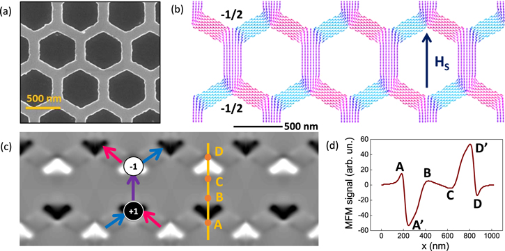
Figure 1. Micromagnetic configuration of the honeycomb array. (a) SEM image of Co honeycomb array. (b) Micromagnetic simulation of Co honeycomb array at easy axis remanence. Note the presence of −1/2 half vortices at opposite bar sides. (c) Simulated MFM contrast image from the micromagnetic configuration in (b) at 50 nm lift height. Sketch shows average magnetization direction at each bar and spin ice charge at the intersection. (d) Contrast profile along the vertical line marked in c.
Download figure:
Standard image High-resolution imageWe begin describing the particular magnetism of the honeycomb array (see figure 1(b)), focusing on the distinctive magnetic states in the vertices of the array. A simple and ordered magnetic configuration can be obtained at remanence when the saturating magnetic field is applied along one of the three magnetic easy axes of the structure; that is, parallel to any to the three nanobar directions of the honeycomb pattern. This can be seen, for example, in the micromagnetic simulation of figure 1(b) for a field applied along the vertical axis of the array. In our case the applied saturating magnetic field was 7 T. In the remanent magnetic state the magnetization lies parallel to each of the bars in the image, surrounding the hexagonal holes of the honeycomb pattern, so that the remanent magnetization MR is parallel to the saturating field direction HS. This magnetic configuration can be described with two distinct but related topological descriptions depending on whether we focus on the dipolar orientation of each bar in the array (spin ice charges [28, 31, 41, 42]) or we focus on the detailed micromagnetic configuration at each vertex (Néel walls and magnetic half vortices [33, 34]).
Starting with the former; i.e. the dipolar description, which can be observed in the simulated MFM image of figure 1(c) and in the experimental MFM image of figure 2(a), we notice white or black contrast regions at each intersection of the honeycomb lattice arranged in two interleaving triangular lattices. The different magnetic contrast is created by the net magnetization divergence in each kind of intersection: (a) white regions correspond to magnetization pointing into the intersection at one of the bars and out in the other two (see sketch in figure 1(c)), that is, to one-in/two-out (−1 spin-ice charge); (b) black regions correspond to magnetization pointing into the intersection at two of the bars and out in the remaining one, that is to a two-in/one-out (+1 spin-ice charge). The ordered arrangement of black/white spots (+1/−1 spin-ice charges) found in figures 1 and 2(a) belongs to the Ice II type [28, 31, 42, 45].
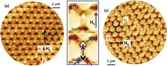
Figure 2. MFM images of the honeycomb array at different remanent magnetic states. (a) Easy axis remanent state. Note the ordered arrangement of white/black spin ice charges corresponding to an Ice II state. (b) Detail of remanent magnetic state configuration of a single bar in the array. Note the V shaped pairs of Neel walls that meet at each bar end corresponding to magnetic half vortices. The lower part of the image shows a sketch of magnetization configuration in the single bar: arrows indicate magnetization direction, V shapes represent the pair of Neel walls with the half vortex core on the tip and black/white color depending on the sign of the ice charge at the intersection (+/−1). (c) Hard axis remanent magnetic state made up of a disordered mixture of white/black spin ice charges of similar intensity corresponding to an Ice I state.
Download figure:
Standard image High-resolution imageNext, if we turn our attention to the local micromagnetic configuration, we observe that Néel walls are generated at the intersections between bars to accommodate the 60° magnetization rotation needed to follow the direction imposed by bar geometry. Magnetic half vortices are found at the points in which a V-shaped pair of Neel walls meets at the sample edge. There is one at each side of the vertical bar with magnetization aligned with HS (and parallel to MR). At both magnetic half vortices there is a –π (counter-clockwise) magnetization rotation corresponding to −1/2 topological index [48]. These magnetic half vortices correspond to black/white regions observed both in the experimental and simulated MFM images (figures 1(c) and 2(b)). The divergence of the magnetization associated to the magnetization rotation at the charged Néel walls generates the stray fields that will provide a magnetic potential for superconducting vortices. Figure 1(d) shows the simulated contrast profile upon crossing a vertical bar bounded by two half vortices from bottom to top of the image. The profile shows an attractive well (between points A and B), corresponding to the black half vortex, and a repulsive hill (between points C and D), corresponding to the white half vortex. Taking into account that pinning forces are given by potential gradients we observe that the asymmetry in the potential is the same in both cases: if forward direction is defined from A to D (i.e. by the remanent magnetization direction) the gradual ascending slopes (A'B and CD') correspond to small backward pinning forces whereas the steep descending slopes (AA' and D'D) correspond to large forward pinning forces. A'B and CD' can be associated to the broad tails of the Neel walls and AA' and D'D to the narrow cores.
In general, magnetization rotation in a Néel wall is not uniform [49]: there is a central narrow core of fast magnetization rotation (of width Wcore determined by the competition of exchange and magnetostatic interactions) surrounded by a pair of broad tails in which the magnetization rotates slowly (of width Wtail determined by the competition between magnetostatic interactions and magnetocrystalline anisotropy K). Then, the intrinsic asymmetry of the magnetic potential can be estimated [49] from the width of the Néel core Wcore = 2(2 A/μ0Ms2)1/2 in comparison to the width of the Neel tail WTail = 0.56t (μ0Ms2/2 K), which for a Co film of thickness t = 20 nm, is of the order of Wcore/Wtail = 10 nm/1 μm = 0.01. The simulated profile shows a reduced asymmetry Wcore/Wtail = 0.25 due to a broadening of the effective domain wall core by convolution with the stray field from the MFM tip and to the confinement of the domain wall tails by the patterned honeycomb structure. In any case, we arrive at two important conclusions: first, the asymmetric potentials are linked to each of the individual half vortices in the bar; i.e. they do not depend on any specific sequence of +1 and −1 charges. This is; the asymmetry origin is not related to magnetic dipole as has been reported before [25–27, 32]. Second, the sign of the asymmetry is the same for the black and white half vortices, and it is correlated in the whole honeycomb array by the magnetization rotation, clockwise or counter-clockwise, imposed by array geometry around the hexagonal holes. Therefore, the specific topology of the array is the clue for reaching this magnetic configuration.
In conclusion, combining these two approaches (micromagnetic and spin ice), we can describe the magnetic configuration of the Co honeycomb lattice in terms of two kinds of −1/2 magnetic half vortices, either associated with a +1 ice charge (black half vortex) or with a −1 ice charge (white half vortex); and interestingly each vertex contains two charged Néel walls.
Finally, spin ice geometry allow studying what happens when we disorder the magnetic potentials. Disorder can be easily introduced in the honeycomb Co lattice by changing the magnetic history with a variety of possible metastable configurations. Ice I states [28, 31, 42], for example, are characterized by a random mix of −1 and +1 spin ice charges (i.e. of negative/positive magnetic charges at the intersections of the honeycomb lattice). For example, if we apply a 7 T saturating magnetic field in the hard direction, i.e. perpendicular to one of the bar directions, the MFM image reveals a disordered remanent magnetic state, as shown in figure 2(c), in which black and white magnetic charges are randomly intermixed. The intensity of the MFM signal is very similar in all the vertices of the image indicating that this configuration state is made of a disordered arrangement of +1/−1 spin ice charges, corresponding to an Ice I state [28, 31, 42].
3.2. Superconducting characterization
This rich magnetic scenario can be exploited to control the dynamics of superconducting vortex lattice using different knobs, each one with different functionalities. Following the previous analysis, there are three different properties of the Co honeycomb array (see figure 3(a)) that can be used to control superconducting vortex motion in this superconducting/magnetic hybrid system. First, the array provides a structural basis to nucleate magnetic topological defects with fixed spatial density and hexagonal symmetry. Second, black/white magnetic charges (+1/−1 spin ice charges) provide attractive/repulsive magnetic pinning potentials for superconducting vortices depending on Hz orientation. Third, local magnetic configuration at the intersections of connected Co bars defines the position of magnetic half-vortices at each cell of the honeycomb array and controls the asymmetry of the magnetic pinning potential. The first two properties of the honeycomb Co array allow knowing whether or not the vortices accomplish a regular distribution along the array. The third condition turns out the clue to obtain a robust and protected ratchet effect.

Figure 3. Superconducting vortex dynamics as a function of order/disorder in the spin ice system. (a) Scanning electron microscopy image of Co honeycomb array with triangle indicating the geometrical dimensions of the lattice of −1 ice charges in Ice II state. (b) Normalized magnetoresistance curve of the hybrid device at 0.98 TC (TC = 8.4 K, RN being the resistance at 10 K) and in the remanent state, after saturating the Co honeycomb array with HS (7 T) along the magnetic easy axis (ordered Ice II configuration). Note the periodic minima in the resistance at regular field intervals μ0Hn. Inset shows μ0Hn versus n linear dependence with slope 4 mT. (c) Normalized magnetoresistance curve of a plain Nb film at 0.98 TC (TC = 8.8 K, RN being the resistance at 10 K). (d) Normalized magnetoresistance curve of the hybrid device at 0.98 TC and in the remanent state, after saturating the Co honeycomb array with HS (7 T) perpendicular to the magnetic easy axis (disordered Ice I configuration). Note the absence of regular magnetoresistance minima in contrast with the behavior observed in (b).
Download figure:
Standard image High-resolution imageWe begin analyzing how vortex lattice motion can be controlled. The particular vortex density is obtained applying the required magnetic field perpendicular to the sample. At temperatures close to the superconducting critical temperature (Tc) the artificially induced periodic potential wells overcome the pinning potentials induced by the random distribution of defects in the sample [50]. Therefore, the moving superconducting vortex lattice could interact with the periodic array of pinning centers. Jaque et al [51] studied the interplay between the superconducting vortex lattice and arrays of periodic nanobars. They found plateaux in the dissipation for specific values of the magnetic fields applied perpendicular to the sample. These plateaux are related to the periodicity of the array. The magnetoresistance, with applied magnetic field perpendicular to the sample, in the superconducting/magnetic hybrid is shown in figure 3(b) (for comparison the usual monotonously increasing magnetoresistance of a plain Nb film is plotted in figure 3(c)). We do not observe plateaux, we observe evenly spaced minima when the Co honeycomb array is at remanence after applying a saturating magnetic field along the magnetic easy axis (see figure 3(b)), i.e. with the honeycomb array in an ordered Ice II configuration. Resistance minima are observed with an average spacing μ0H1 = 4.0 mT (as shown in the inset of figure 3(b)). This finding corresponds to the matching between the vortex lattice and the vertices in the array, as sketched in figure 3(a). Therefore, the vertices in the array act as magnetic pinning potentials. Each time the density of superconducting vortices is an integer number of the density of magnetic pinning centers the superconducting vortex lattice motion slows down, a resistance minimum appears and dissipation decreases. These sharp minima are the footprint of matching effect between the vortex lattice and the triangular unit cell of the charged sublattice [52]. Therefore, the ordered spin ice charge array allows controlling the vortex lattice motion. For the fabricated Co honeycomb lattice, the distance (a) between alternating vertices in the triangular cell (i.e. between spin ice charges of the same sign) is a = 765 nm that corresponds to the first matching field μ0H1 = 1.156 Φ0/a2 = 4.02 mT. Thus, the experimental matching field μ0H1 = 4.0 mT is in good agreement with the calculated matching conditions in the ordered spin ice II configuration. We have to point out that the interaction which governs this behavior is between magnetic stray fields in the honeycomb array vertices (+1/−1 charges) and the superconducting vortices [53]. The ordered Ice II state provides an effective magnetic pinning potential for the superconducting vortex lattice when it matches either the triangular lattice of −1 ice charges (downward magnetic applied fields) or the triangular lattice of +1 ice charges (upward magnetic applied fields). On the contrary, when the Co honeycomb array is in an Ice I configuration, equally spaced resistance minima disappear, as is shown in figure 3(d). That is, matching effects between spin ice charges and the superconducting vortex lattice fade away due to the loss of long range order in Ice I phase: the triangular lattice of superconducting vortices at the first matching field (H1) is randomly attracted/repelled by the positive/negative magnetic charges at the intersections of the honeycomb lattice resulting in a negligible synchronized pinning effect. In summary, the superconducting vortex dynamics can be controlled using the magnetic history of the hybrid superconducting/magnetic sample.
3.3. Ratchet effect
As was quoted before, spatial asymmetries in the magnetic pinning potentials can be probed by superconducting vortex ratchet measurements [19, 25–27]. First, we obtain the superconducting vortices applying perpendicularly magnetic fields at matching conditions Hz = H1. Next an ac current creates an alternating Lorentz force FL on the vortex lattice that results in a rectified vortex velocity, as long as there is an asymmetry between backward/forward pinning forces. In short, an ac current density J = Jac sin(ωt) is injected, where ω is the ac frequency, in our case 1 kHz and t is time. This yields an alternating Lorentz force (FL) on the vortices FL = J × Φ0z, Φ0 and z being the magnetic fluxoid and the unit vector parallel to the applied magnetic field respectively. Albeit the time averaged force on the vortices is zero, taking into account the Josephson expression [54] (E = B × v, being E, B and v the electric field, the magnetic field and the vortex lattice velocity, respectively) an output dc voltage is measured proportional to the rectified vortex velocity. In summary, an ac current input yields a dc voltage output and a ratchet effect is achieved if forward/backward pinning forces are asymmetric. Figure 4 shows the experimental results both when the honeycomb array is in an ordered Ice II state (figure 4(a)) and in a disordered Ice I state (figure 4(b)). In both cases, ratchet voltages of several μV are measured, this net dc voltage is the characteristic outcome for interacting particles moving on asymmetric potentials. Thus, in spite of the very different magnetic configuration, our hybrid Co honeycomb/Nb device works in both cases as a rectifier device: input alternating forces generate output net flow. In order to test the magnetic origin of this ratchet effect the usual analysis has been realized (see figure 5). Different applied directions of Hz and HS are used to test the magnetic origin of the pinning potential asymmetry. In the first case, Hz = +H1 and μ0HS = 7 T (figure 5(a)), a clear positive ratchet voltage is observed, implying a positive rectified superconducting vortex velocity along the in-plane remanent magnetization (see sketch in figure 5 (d)). In the second case, Hz = −H1 and μ0HS = 7 T (figure 5(b)), the magnetic configuration of the honeycomb array stays constant while the superconducting vortex polarity is inverted. The measured ratchet potential is positive, what implies a double sign change in the Josephson electric field equation, i.e. a negative rectified vortex velocity antiparallel to in-plane remanence (as sketched in figure 5(e)). Then, the ratchet curve shown in figure 5(c) corresponds to Hz = −H1 and μ0HS = 7 T, that is, with a negative remanent magnetization of the Co honeycomb array. In this case, a clear negative ratchet potential is measured of similar amplitude as in figure 5(a) that is the result of the motion of –ϕ0 vortices with a positive rectified velocity (see figure 5(f)). Therefore, the combination of these three measurements clearly confirms the magnetic origin of the asymmetry in the pinning potential. However, the detailed comparison of the V versus I curves in figure 5 shows differences between the amplitude of the rectified signal at +H1 (figure 5(a)) and –H1 (figure 5(b)) that cannot be explained with a model of 'fixed' magnetic potentials that are simply reoriented by the magnetic field. These differences could be attributed either to a deformation of the magnetic half vortices by the applied Hz field (similar to the observation of figures 2(b) and 3(b)) or to small structural asymmetries in the honeycomb array.

Figure 4. Rectification of superconducting vortex motion by Co honeycomb array. Rectified ratchet voltage in the hybrid device at Hz = H1 after two different saturation field configurations: (a) μ0HS = 7 T parallel to easy axis (ordered Ice II state) and (b) μ0HS = 7 T perpendicular to the magnetic easy axis (disordered Ice I configuration).
Download figure:
Standard image High-resolution image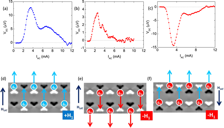
Figure 5. Superconducting ratchet potential at 0.98 TC with: (a) μ0HS = 7 T parallel to easy axis and Hz = +H1; (b) μ0HS = 7 T parallel to easy axis and Hz = −H1; (c) μ0HS = 7 T parallel to easy axis and Hz = −H1; (d)–(f) sketches summarizing relative orientation of magnetic potential and rectified vortex velocity in the different configurations in (a)–(c).
Download figure:
Standard image High-resolution imageTo figure out the origin of this behavior we have to take into account the geometrical distribution of the magnetic half vortices comprising two Néel walls at each vertex of the honeycomb lattice, and this has to be done according to the ice rules. We can obtain a rough sampling of the half vortex geometrical distribution analyzing the MFM experimental data. As was indicated in figure 2(b), direct comparison between MFM experimental images and simulated MFM contrast allows establishing the average magnetization orientation at individual Co bars at each vertex in the honeycomb lattice. This procedure is carried out by taking into account ice rules and half vortex asymmetries to draw the magnetization vectors in a consistent way (see figure 6). Then, at each intersection, the orientation of magnetic half vortices is univocally determined by the local magnetic configuration, i.e. by the intersection edge at which the –π rotation of the half vortex is localized. In brief, in the case of ordered Ice II configuration (see figures 6(a)), +1/−1 ice charges are arranged in a triangular lattice (see figures 6(b), (c)), existing only two kinds of magnetic half vortices in the image (see figure 6(d)) black and white. The V-shaped pairs of domain walls of these two half vortices point in opposite directions but, due to their opposite magnetic charges (+1 and −1), both of them provide magnetic potentials with the same asymmetry for vortices travelling along the easy axis, as shown in the simulated profile of figure 1(d). Thus, the ordered configuration of black/white half vortices in Ice II state is consistent with the net rectified vortex velocity observed in the experimental results of figure 4(a). Also, the existence of two kinds of asymmetric potentials (black/white half vortices) could explain the observation of two maxima in the V versus I curve of figure 4(a).

Figure 6. Analysis of topological defects from MFM image in ordered Ice II configuration. (a) MFM image of honeycomb array. (b) Sketch of local magnetization orientation and half vortex position. (c) Sketch of magnetization configuration and spin ice charges. (d) Sketch of configuration of magnetic half vortices. Note that in this ordered Ice II configuration +1 (or −1) ice charges are arranged in a hexagonal lattice and there are only two kinds of magnetic half vortices in the image.
Download figure:
Standard image High-resolution imageOn the other hand, in the disordered Ice I configuration, there is not long range order in the configuration of +1/−1 ice charges and different orientations of the magnetic half vortices can be observed. Figure 7 shows a detailed analysis of the magnetic configuration and topological defects in the honeycomb array in the hard axis remanent state following the method described in figure 6. First, the experimental MFM image (figure 7(a)) is used to calculate the magnetization orientation at each bar of the array (figure 7(b)) and the location of white magnetic half vortices (figure 7(c)) and black magnetic half vortices (figure 7(d)). The spatial configuration of black/white magnetic charges is disordered in most of the sample with a large distribution of nearest neighbor distances in agreement with the absence of periodic minima in figure 4(b). However, the disordered configuration is not fully symmetric: a non-zero remanent magnetization Mrem can be estimated summing up the magnetization of all the bars in the image. Mrem is almost parallel to the direction of the last saturating field, as indicated in the sketches of figures 7(c), (d). In principle, in a fully disordered symmetric configuration, magnetic half vortices should be found at any of the six vertices of the hexagonal holes in the honeycomb array, linked either to a −1 spin ice charge (white) or to a +1 spin ice charge (black). These results in 12 possible types of magnetic half vortices (see sketches in figures 7(c), (d)). However, the disordered state shown in figure 7 has been obtained by applying a magnetic field along the hard axis of the array and reducing it to zero. This procedure breaks the spatial symmetry of the hexagonal array and only 6 of these possibilities are actually observed in the hard axis remanent state (3 black and 3 white) which correspond in 90% of the cases to the orientations closest to the remanent magnetization direction. That is, a non-zero Mrem breaks the symmetry among the 12 possible orientations of magnetic half vortices so that only six of them are observed, and with an uneven distribution (see numbers in sketches of figures 7(c), (d)). The remanent magnetization calculated from the MFM image is not perfectly perpendicular to the easy axis direction which can be due to a small misalignment between the applied field and the hard axis.

Figure 7. (a) MFM image of honeycomb array in a disordered state after transverse saturation; (b) sketch of individual magnetization in each array bar corresponding to the magnetic contrast in panel (a); the corresponding spatial distribution of white/black magnetic half vortices is sketched in (c)/(d), respectively. V shapes represent the pair of Neel walls with the half vortex core on the tip. Insets show a sketch of possible magnetic half vortex configurations in Co honeycomb lattice. Numbers in squares indicate the actual count for each kind of half vortex present in (c) and (d). Mrem arrow indicates the remanent magnetization orientation calculated from the sum of individual bar magnetizations in (b).
Download figure:
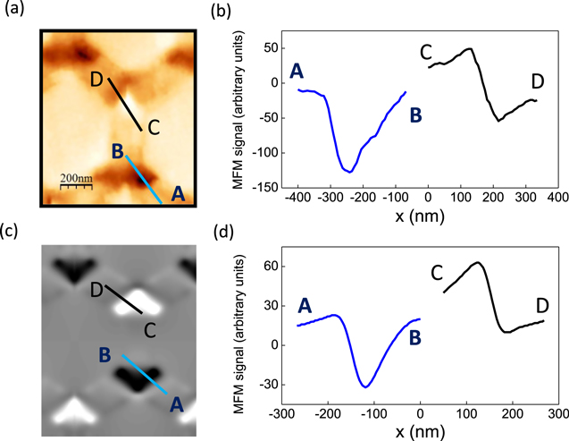
Standard image High-resolution imageExperimental and simulated MFM profiles shown in figure 8 indicate that individual magnetic half vortices provide asymmetric pinning potentials for superconducting vortices travelling across magnetic half vortices not only from tip to base but also in oblique trajectories, even though with a different strength and degree of asymmetry. Thus, the six different kinds of half vortices present in the disordered state could explain the small 'bumps' in the V versus I curve observed in figure 4(b).
Figure 8. Experimental and simulated potential profiles. (a) Experimental MFM image of a single bar in the array. (b) AB and CD profiles from experimental MFM image in (a). (c) Simulated MFM image of a single bar in the array. (d) AB and CD profiles from simulated MFM image in (c). Note the clear asymmetry upon crossing the Neel walls that emerge from −1/2 edge vortices (steep descending versus gradual ascending slopes) with the same sign in AB and CD profiles.
Download figure:
Standard image High-resolution image
Therefore, the superconducting ratchet signal observed in figure 5(b) reveals that the vortex lattice is sensitive to this subtle symmetry breaking in the Ice I state. Taking into account that the strength of the asymmetry depends on the local vortex lattice direction of motion (see figure 8) it is difficult to calculate the average strength of the effective rectifying potential. However, zero ratchet effect would require a full degree of disorder in the lattice (probably with zero magnetic remanence, and a balanced distribution of all the possible half vortices in the system). Zero magnetization ground states are hard to reach in the ice I phase of artificial spin ices due to the large variety of possible metastable configurations [55], which results in a robust ratchet signal. It must be noted that any residual spatial asymmetries, particularly related with array edges, will also add to the rectified ratched signal in the disordered state [56].
Thus, we have obtained a robust and resilient ratchet device which works independently of the magnetic history of the device.
4. Conclusion
In summary, we have designed, fabricated and measured a superconducting ratchet device using, as the origin of the needed asymmetric potentials, magnetic half vortices with charged Néel walls in a spin ice honeycomb array and superconducting vortices driven by alternating forces as the needed out-of-equilibrium particles. Magnetic half vortices are topologically confined at the honeycomb lattice intersections but their global configuration depends on spin ice states generated by magnetic frustration in the Co honeycomb arrays. The interplay among superconducting vortices, magnetic frustration, topology and spin ice states lead to a rich experimental scenario. Eventually our device can be controlled with three distinct topological defects, each one with a different functionality. We have superconducting vortices, +1/−1 magnetic charges in the spin ice with their associated stray fields, and −1/2 half-magnetic vortices linked to a couple of charged Néel walls in each vertex of the Co honeycomb array. It is found that when superconducting vortices are pushed by zero average alternating forces, a net flow is always measured, independent of the magnetic history of the sample. The mechanism responsible for the ratchet effect is independent of whether the sample is in an ordered (Ice II) or in a disordered state (Ice I). In both cases, the ratchet effect is generated by the asymmetry in the magnetic potential due to the asymmetric profile of the charged Néel walls that compose each magnetic half vortex.
This basic symmetry breaking mechanism is protected by the non-trivial topology of a hole in a magnetic film that creates a pair of magnetic half vortices at opposite sides of the hole with correlated chirality. The periodic array of holes in the honeycomb lattice results in a periodic array of magnetic half vortices and in an enhanced interaction with the superconducting vortex lattice at matching conditions. Then, the observed rectification of superconducting vortex motion in the absence of periodic pinning effect relies on a subtle effect: the correlation of potential asymmetries of magnetic half vortices imposed by the link between non zero remanent magnetization and the local rotation of in-plane magnetic moments around the holes in the honeycomb structure.
Acknowledgments
We thank support from Spanish MINECO grants FIS2016-76058 (AEI/FEDER, UE), Spanish CM grant S2013/MIT-2850. IMDEA Nanociencia acknowledges support from the 'Severo Ochoa' Programme for Centres of Excellence in R&D (MINECO, Grant SEV-2016-0686). DG acknowledges RYC-2012-09864, S2013/MIT-3007 and ESP2015-65597-C4-3-R for financial support and AG acknowledges financial support from Spanish MINECO Grant ESP2015-65597-C4-1-R.