

Abstract
A novel approach for the fabrication of nickel oxide nanotubes based on multiwalled carbon nanotubes as a sacrificial template is described. Electroless deposition is employed to deposit nickel onto carbon nanotubes. The subsequent annealing of the product in the presence of air oxidizes nickel to nickel oxide, and carbon is released as gaseous carbon dioxide, leaving behind nickel oxide nanotubes. Electron microscopy and elemental mapping confirm the formation of nickel oxide nanotubes. New chelating polyelectrolytes are used as dispersing agents to achieve high colloidal stability for both the nickel-coated carbon nanotubes and the nickel oxide nanotubes. A gravimetric specific capacitance of 245.3 F g−1 and an areal capacitance of 3.28 F cm−2 at a scan rate of 2 mV s−1 is achieved, with an electrode fabricated using nickel oxide nanotubes as the active element with a mass loading of 24.1 mg cm−2.
Export citation and abstract BibTeX RIS
1. Introduction
Carbon neutral solutions require not only renewable energy generation but also efficient energy storage devices. Novel synthesis processes that produce novel active materials for these devices will improve their affordability and performance. Quasi one-dimensional (1D) nanostructures, such as nanoparticles, nanotubes and nanowires, have intrinsically large surface area to volume (hence mass) ratios, short diffusion lengths for charge and mass transport, and substantial volume change capacities, making them suitable for next-generation energy storage devices [23]. Many nanostructures also exhibit superior electrochemical performance [9, 22].
Pseudocapacitors are a class of supercapacitors that store Faradaic current through charge transfer between an electrode and an electrolyte [8, 19]. Conducting polymers and transition metal oxides, such as ruthenium oxide (RuO2), iridium oxide (IrO2), manganese dioxide (MnO2), bismuth oxide (Bi2O3), cobalt oxide (Co3O4), iron oxide (Fe3O4) and nickel oxide (NiO), are electrode material candidates for pseudocapacitors [27], although fabrication cost is an issue. Among transition metal oxides with p-type semiconducting properties, NiO exhibits higher theoretical capacitance, charge density and chemical stability [7, 33, 35, 38, 46]. The gravimetric specific capacitance of metal-oxide-based electrodes decreases with an increasing electrode mass [12, 17, 27, 39, 44]. The charge in pseudocapacitors is stored mostly on the surface of the active material, reducing the active mass, which is favorable for electrochemical performance [16, 41] and thus decreases the specific capacitance [7, 9, 43, 48]. Supercapacitor electrodes containing active materials and conductive additives also benefit from tubular and fibrous microstructures [10, 20, 43] that enhance charge transfer and electrolyte access to the active material, and reduce the amount of binder that is introduced.
Due to their small crystal size, high aspect ratio and hollow microstructure, nickel oxide nanotubes (NiONTs) show promise for sensing [38, 40], catalysis [15] and energy storage applications such as batteries [24, 31, 32, 46] and supercapacitors [45, 49]. The performance of NiO-based supercapacitors [11, 13, 27, 29, 39] is enhanced by fabricating electrodes that have high NiO mass loadings. Practical applications require high specific capacitance for a mass loading of 10–20 mg cm−2 [14]. Hence, NiO and other charge storage materials are typically combined with conductive additives, such as Ni, multiwalled carbon nanotubes (MWNTs) and graphene to fabricate composite electrodes that show improved electronic conductivity [12, 39, 43].
Since NiONT applications are limited by the lack of simple, low-cost fabrication methods, we propose a new scalable way of overcoming these limitations. We encapsulate MWNTs with Ni by depositing the metal through electroless deposition to synthesize the Ni-MWNT hybrid material [1–4, 6, 21]. These encapsulated nanotubes are annealed in air at temperatures much lower than the melting temperature of Ni so that the metal and carbon in the MWNTs oxidizes to NiO and CO2. Release of the gaseous carbon dioxide results in a tubular vacancy where the MWNT existed previously. Thus, the residual NiO retains the shape of the (now oxidized) underlying MWNT template, producing a NiONT. The wall thickness of this nanotube may be controlled by varying the mass of Ni that is deposited, which could allow control over the dimensions of the synthesized NiONTs. We investigate NiONT charge storage by using these nanotubes in the electrode of an electrochemical supercapacitor.
2. Materials and methods
2.1. Materials and reagents
Commercially available MWNTs purchased from US Research Nanomaterials Inc. with purity >95%, an outer diameter of 20–30 nm, an inner diameter of 5–10 nm, and a length between 0.5–2.0 μm are used as specified by the manufacturer. Other reagents included nickel (II) chloride (NiCl2, 98%, Alfa Aesar), nickel (II) sulfate hexahydrate (NiSO4 · 6H2O, 99%, Sigma-Aldrich), sodium hydroxide (NaOH, 97%, Caledon Laboratory Chemicals), hydrochloric acid (HCl, 36.5%–38%, Caledon), stannous chloride dihydrate (SnCl2 · 2H2O, 98%, Caledon), ammonium chloride (NH4Cl, ACS grade, BDH/VWR International), sodium citrate dihydrate (Na3C6H5O7 · 2H2O, 99%, EMD chemicals Inc.), sodium hypophosphite monohydrate (NaH2PO2 · H2O, lab grade, Anachemia Canada Co.), and palladium (II) chloride (PdCl2, 100%, Artcraft chemicals Inc.). Poly(4-styrenesulfonic acid-co-maleic acid) sodium salt (PSSA, Mw = 20 kDa), Poly[1-[4-(3-carboxy-4-hydroxyphenylazo)benzenesulfonamido]-1, 2-ethanediyl, sodium salt] (PAZO, Mw = 65–100 kDa) and Poly(vinyl butyral-co-vinyl alcohol-co-vinyl acetate) (PVB, Mw = 50–80 kDa) were obtained from Sigma-Aldrich. Ni foams with a porosity of 95% were supplied by the Vale Company. All reagents were used as received without further purification.
2.2. Synthesis of nickel oxide nanotubes (NiONTs)
Synthesis of the nickel oxide nanotubes is schematically illustrated in figure 1(a). Initially, MWNTs were sensitized with a stannous chloride solution and then catalyzed with palladium through treatment with palladium chloride solution [1, 3, 6, 18, 47] both under ultra-sonication with a probe sonicator (Qsonica, LLC, Model: Q500 with 1/4ʺ micro-tip at 35% power) for 30 min. The catalyzed MWNTs were washed with water and dried in a vacuum oven after each treatment step. The catalyzed MWNTs were electrolessly plated with nickel nanocrystals through chemical reduction of the Ni+2 contained in the plating solution by the electrons provided by sodium hypophosphite (NaH2PO2), which acted as a reducing agent. Since the reaction was constrained to the catalytic surfaces of the MWNTs, a continuous nickel layer was deposited that encapsulated the entire nanotube [1–3, 42]. The autocatalytic Ni surface continued to facilitate nickel deposition, even after the original MWNT surface had been completely encapsulated [47].
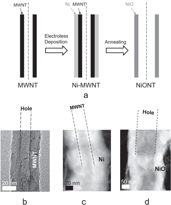
Figure 1. Synthesis of nickel-oxide nanotubes. (a) A schematic of the synthesis process for nickel oxide nanotubes (NiONTs) involving the electroless deposition of Ni on MWNT, the oxidation of Ni to NiO, and the carbon in the MWNT to gaseous CO2. The carbon dioxide is released, producing a tubular vacancy in the NiO bulk where the MWNT originally existed. (b) A TEM image of an MWNT, (c) a dark field STEM image of a Ni-MWNT, and (d) a dark field STEM image of a NiONT.
Download figure:
Standard image High-resolution imageThe thickness of the Ni layer was changed by varying the Ni:MWNT weight ratio (γ = 1 and 7). For each gram of MWNTs desired, a plating solution was prepared [1]. For two particular experiments, the solution consisted of NiCl2 (1.7 g), NiSO4 · 6H2O (1.1 g), NH4Cl (5.5 g), Na3C6H5O7 · 2H2O (4 g), NaH2PO2 · H2O (5 g) and DI water (100 ml) for γ = 1, and NiCl2 (11.9 g), NiSO4 · 6H2O (7.7 g), NH4Cl (38.5 g), Na3C6H5O7 · 2H2O (28 g), NaH2PO2 · H2O (35 g) and DI water (700 ml) for γ = 7. The electroless deposition of Ni over the MWCNT was conducted at pH ∼ 9–10. Sodium hydroxide solution (2 N) was added dropwise to maintain the reaction pH, which was monitored with a pH meter at 5 min intervals, with a probe sonicator simultaneously used to continuously sonicate the medium for 60 min. The reaction products were immediately washed and dried to obtain Ni-MWNTs.
The two Ni-MWNT samples for γ = 1, 7 were annealed at ≈500 °C for 2 h in the presence of air to oxidize Ni to NiO and the MWNT carbon content to CO2. Release of the carbon dioxide left a tubular vacancy inside the NiO bulk, leading to the formation of NiONTs. The resulting nanotube samples are labeled NiONT-1 for γ = 1 and NiONT-2 for γ = 7.
2.3. Preparation of colloidal suspension of Ni-MWNT and NiONT
Electrode fabrication for testing electrochemical performance requires a very stable colloidal suspension of the active material. The prepared NiONT serves as the active material and the Ni-MWNT serves as a conductive additive to achieve high specific capacitance at high active mass loadings by dispersing and mixing these components.
Dynamic light scattering (DLS, DelsaMax Pro: Beckman Coulter) was used to measure the effect of two different dispersing agents, i.e., PAZO and PSSA, on the colloidal stability of the Ni-MWNTs and NiONTs. Dispersions in PAZO were prepared by dissolving 1 g l−1 of the substance in a 75% ethanol solution, followed by dispersing 4 g l−1 of the solid material using the probe sonicator for 30 min. Dispersions in the PSSA were prepared by dissolving 1 g l−1 of the compound in a 60% ethanol solution, again followed by dispersing 4 g l−1 of the solid material and using the probe sonicator for 30 min. Both solutions were diluted further to take stability measurements using DLS.
2.4. Characterization methods
X-Ray diffraction (XRD) analysis of the samples was performed using a Bruker D8 Discover instrument comprising a DavinciTM diffractometer operating at 35 kV and 45 mA using Co-Kα radiation (λavg = 1.79026 Å). Bruker's DIFFRAC.Eva V3.1 software was used for qualitative analysis of the constituent phases. Scanning transmission and transmission electron microscopy (dark field STEM/TEM) and energy dispersive x-ray (EDX) spectroscopy were conducted with a JEOL 2010F field emission microscope. For STEM/TEM, the samples were suspended in ethanol, dropped onto a TEM copper grid, and then wicked off with a Kimwipe.
2.5. Electrochemical performance testing
Electrochemical characterization of the fabricated electrode was carried out using a standard three-electrode system using a potentiostat (PARSTAT 2273, Princeton Applied Research). The surface area of the working electrode was 1 cm2. The counter electrode was a platinum gauze, and the reference electrode was a standard calomel electrode (SCE). The characterization was conducted in 1 M KOH aqueous solution using (i) cyclic voltammetry (CV) and (ii) electrochemical impedance spectroscopy (EIS).
The CV measurements were performed within a 0–0.5 V potential range versus the SCE as the reference electrode, and the data recorded by PowerSuite electrochemical software. The CVs were obtained at scan rates of 2–100 mV s−1. The charge Q was calculated based on half of the integrated area of the CV curve. The integrated capacitance CS = Q/ΔVS was determined by dividing Q by the width of the potential window ΔV and the electrode area S. Alternating current measurements of the complex impedance Z* = Z' – iZ'' were performed in the frequency range 10 mHz to 100 kHz for a signal amplitude of 5 mV. The complex differential capacitance CS* = CS'–iCS'' was determined from the impedance data through the relation CS' = Z''/ω∣Z∣2S and CS'' = Z'/ω∣Z∣2S, where ω = 2πf and f denotes frequency.
3. Results and discussion
3.1. Synthesis of NiONT: characterization and elemental analyses
Figures 1(b) and (c), respectively, present TEM images of the MWNT before and after electroless deposition of a layer of nickel that encapsulates it. Comparison of the images in figures 1(b), (c) and (d) with their scale bars indicates that Ni deposition on the MWNT at γ = 7 is ≈40–50 nm. Annealing of Ni-MWNT results in oxidation of both nickel and carbon, which leaves a ≈50 nm tubular vacancy, as shown through the dark field STEM image of a NiONT in figure 1(d).
The XRD analysis presented in figure 2 confirms the existence of crystalline nickel (Ni, PDF no. 00-004-0850) and hexagonal carbon (multiwalled carbon nanotubes, PDF no. 00-058-1638) on the Ni-MWNT samples for the two different Ni:MWNT weight ratios γ = 1 and 7. Comparing the ratios of the intensities of the diffraction peaks for the Ni (111) and (200) planes, and likewise for the MWNT (002) and (004) planes for the two samples, shows how the amount of deposited nickel increases by increasing the Ni:MWNT weight ratio. The XRD patterns for the annealed NiONT samples NiONT-1 and NiONT-2 confirm the absence of MWNTs and Ni, since these two materials are oxidized to CO2—which is released and NiO. Here, the diffraction peaks corresponding to nickel oxide (NiO, PDF no. 01-089-3080) confirm the presence of NiONTs, supporting our hypothesis of the formation of a crystalline nickel oxide phase.
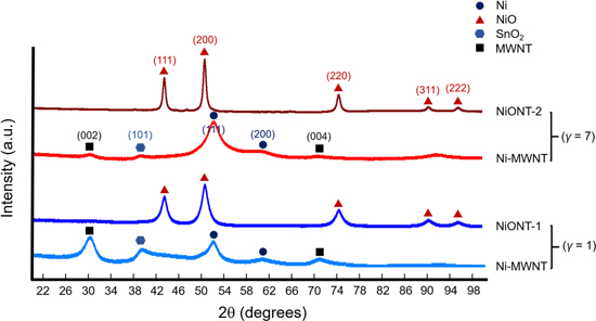
Figure 2. XRD patterns for the Ni-MWNTs and NiONTs for two different Ni:MWNT weight ratios, i.e., γ = 1 and 7. The absence of diffraction peaks corresponding to MWNTs, and the appearance of a diffraction peak corresponding to nickel oxide after annealing, confirms the removal of carbon and the oxidation of Ni to NiO.
Download figure:
Standard image High-resolution imageFigure 3 presents the dark field STEM images of the as-prepared NiONT for γ = 1 and 7. The STEM images for NiONT-1 (figure 3, panels a.1–a.5) show that both nickel oxide nanotubes and nickel oxide agglomerates are present, creating porous structures. The average outer diameter of the NiONTs is ≈60–80 nm, the average inner diameter ≈30–40 nm and the average wall thickness ≈10–25 nm. The STEM images for NiONT-2 (figure 3, panels b.1–b.5) show that NiO agglomeration is reduced. Here, the average NiONT outer diameter ≈160–180 nm, the average inner diameter ≈60–80 nm, and the average wall thickness ≈40–60 nm. The thin and porous Ni coating (∼10–25 nm) [1] on the MWNT for γ = 1 has a relatively low thermal stability, so that it undergoes sintering during annealing [2, 3] into porous microstructures, as shown in figure 3, panels a.1–a.2. This is also evident from the morphology and the internal cavity in the NiONT-1, which are neither smooth nor continuous, as shown in figure 3, panels a.4–a.5. In contrast, for γ = 7, the thickness of the Ni layer deposited on the MWNT is ≈40–60 nm [1], which is thermally more stable so that the tubular shape of the individual MWNTs is retained during annealing, as is evident from figure 3, panel b. Additionally, the morphology and the internal cavity for the NiONT-2 are smooth and continuous, as shown in figure 3, panels b.3–b.5. These images indicate that larger NiONT agglomerates are produced when γ = 1 and more distinct tubular vacancies remain when γ = 7.
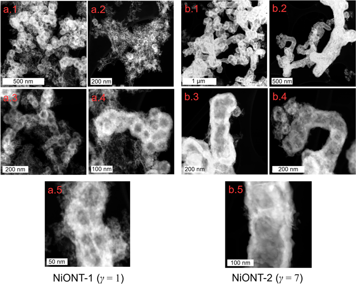
Figure 3. STEM images of NiONT for two different Ni:MWNT weight ratios γ = 1 and 7 at different magnifications. Panels a.1–a.5 show dark field STEM images of NiONTs produced at γ = 1. Panels b.1–b.5 likewise show dark field STEM images for NiONT synthesized at γ = 7.
Download figure:
Standard image High-resolution imageThe EDX/STEM line scans for samples NiONT-1 and NiONT-2 are presented in figure 4, panels a.1 and b.1, respectively. The line scans, taken across the cross-sections of the respective NiONTs shown in the accompanying STEM images, confirm the existence of elemental Ni and O and the absence of C in both samples. As evidence of vacancies, the magnitudes of the Ni and O line scan profiles are significantly reduced inside the nanotubes. The EDX/STEM elemental mapping for NiONT-1 and NiONT-2 is presented in figure 4, panels a.2 and b.2, respectively. These maps provide additional confirmation that while Ni and O exist together outside the vacancies, there is a negligible amount of C in either sample. The small indication of elemental C is attributed to the background lacey grid used to hold the TEM samples.

Figure 4. The EDX elemental analyses of NiONT for elemental Ni, C and O (panels a.1 and b.1), along with line scans of the NiONTs synthesized at γ = 1 and 7, respectively. The line scans are taken across the cross-sections of the respective NiONTs shown in the accompanying STEM images. Panels a.2 and b.2 contain elemental maps of the NiONT for γ = 1 and 7, respectively.
Download figure:
Standard image High-resolution image3.2. Stability of the colloidal suspension
The chemical bonding of the dispersants to the particle surfaces is a prerequisite for efficient dispersion. Previous investigation [5] has shown that charged molecules with chelating ligands provide efficient dispersion of oxide nanoparticles. Since molecules with single chelating ligands lead to relatively weak interactions with the particle surface, the efficient dispersion of relatively large nanotubes requires stronger adsorption of the dispersant, such as the one containing multiple chelating ligands [25, 26].
The chelating polyelectrolyte, PAZO (figure 5(a)) is a dispersing agent that was recently employed for the efficient dispersion and colloidal processing of the nanoparticles [25, 26]. It is an anionic polyelectrolyte containing chelating monomers (figure 5(a)). The salicylate groups of such monomers provide multiple adsorption sites, facilitating strong bonding to the particle surface. Figure 5(b) illustrates the bonding of a PAZO monomer, which involves the complexation of a metal atom on the particle surface. The creation of multiple bonds leads to strong PAZO adsorption on nanoparticles of different types, including oxides, hydroxides and metals. Therefore, PAZO is a promising material for the dispersion of larger nanoparticles, such as NiONTs and Ni-MWNTs. The successful colloidal processing of nanoparticles using PAZO has generated interest in the search for new chelating polyelectrolytes and the investigation of new bonding mechanisms, and PSSA attracted our attention as a chelating polyelectrolyte. Its chelating properties are related to carboxylic groups of PSSA monomers (figure 5(c)). It is known that PSSA forms complexes with metal ions in solutions [28, 36, 37]. The chelating mechanism involves two carboxylic groups of each monomer [28]. We suggest that a similar mechanism leads to the complexation of Ni atoms on the NiONT and Ni-MWNT surfaces (figure 5(d)). We also hypothesize that multiple chelating bonds result in the efficient adsorption of PSSA on both materials, which is important for their co-dispersion, the prevention of agglomeration and improved mixing.
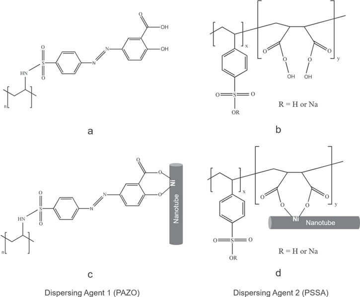
Figure 5. The chemical structures of (a) PAZO and (b) PSSA and the corresponding adsorption mechanisms involving the complexation of (c) the salicylate groups of PAZO and (d) the carboxylic groups of PSSA with Ni atoms on the surfaces of (c) the Ni-MWNT and (d) the NiONT.
Download figure:
Standard image High-resolution imageOur aim is to fabricate a composite electrode with NiONTs (γ = 1 and 7) as the active material and Ni-MWNTs (γ = 1) as the conductive additive, and characterize its electrochemical performance. The electrochemical performance of the electrode has a strong dependence on the microstructure of the active material. Good dispersion and mixing of the individual components in the composite active material are of critical importance for the development of advanced electrodes. Therefore, we paid attention to the dispersion and mixing of the individual components in the slurries, used for electrode fabrication.
We used Ni-MWNTs (γ = 1) only as the conductive additive, since their thin nickel layer reduced the charge transfer length as well as the specific mass of the electrode. The thin Ni layer allowed the adsorption of PAZO and PSSA by mechanisms involving the chelation of surface Ni atoms (figures 5(c)–(d)). A similar mechanism, involving the chelation of Ni atoms on the NiONT surface allowed PAZO and PSSA to be adsorbed on the active material. Six different suspensions were prepared for three materials, i.e. NiONT-1, NiONT-2 and Ni-MWNT (γ = 1), with two dispersing agents, i.e. PAZO and PSSA, which were subjected to sedimentation tests and DLS.
The sedimentation tests showed that the addition of PAZO or PSSA to the Ni-MWNT and NiONT suspensions resulted in improved suspension stability. Measurements of electrophoretic mobility showed that the Ni-MWNT and NiONT were negatively charged. Figure 6 shows that the electrophoretic mobilities of Ni-MWNT (γ = 1) in the suspensions containing PAZO and PSSA were −0.40 and −0.82 μmcms−1V−1, respectively. In addition, NiONT-2 had higher electrophoretic mobility in both (PAZO and PSSA) suspensions (−0.84 and −1.14 μmcms−1V−1, respectively) than NiONT-1 (−0.67 and −0.91 μmcms−1V−1, respectively). The lower suspension stability of NiONT-1 is attributed to the formation of a larger number of microscopic agglomerates, as discussed in section 3.1. Since fewer tubular vacancies remain in the structure, there is a significant reduction in the surface area to mass ratio, which reduces the suspension stability of these particles. Thus, NiONT-2 was preferred over NiONT-1 for electrode fabrication.
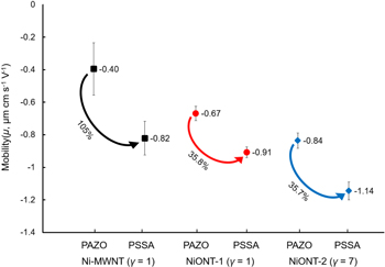
Figure 6. Electrophoretic mobility of Ni-MWNTs (for γ = 1) and NiONTs (for γ = 1 and 7) with two dispersing agents, PAZO and PSSA.
Download figure:
Standard image High-resolution imageThe use of PSSA as a dispersant allowed for improved suspension stability and higher electrophoretic mobility as compared to PAZO for all the samples. The higher dispersion and electrophoretic mobility for both Ni-MWNTs and NiONTs achieved with PSSA is due to stronger PSSA adsorption on both types of nanoparticle. From the perspective of polyelectrolyte adsorption, the chelating groups exert a strong influence on polymer adsorption. The adsorbed polymer provides the electrosteric dispersion of Ni-MWNT and NiONT, which facilitates their improved mixing.
3.3. Electrochemical performance
Based on the suspension test results, the electrode was fabricated with NiONT-2 as the active material, Ni-MWNT (γ = 1) as the conductive additive, and PSSA as the dispersing agent. A probe sonicator was used for 30 min to prepare a dispersion containing a 5 ml PSSA solution (0.4 g l−1 in 60% ethanol solution), 2 ml PVB binder solution (0.75 g l−1 in 100% ethanol solution), 40 mg NiONT (γ = 7), and 10 mg of Ni-MWNT (γ = 1). The prepared colloidal dispersion was heated overnight at 60 °C until a dense slurry was obtained. This slurry was used to impregnate the Ni foam current collector, which was dried thereafter in air and subsequently pressed to 30% of its original thickness using a rolling press. The mass of the impregnated material was 24.1 mg cm−2.
The prepared electrode was tested for electrochemical performance using a potentiostat. Figure 7(a) shows the typical CV results at different scan rates. The shape of the CVs in the selected voltage window of 0–0.5 V is similar to the corresponding literature data for NiO composites prepared by other methods [12, 16, 27, 29, 30, 33]. The gravimetric specific capacitance of 245.3 F g−1 is comparable to the literature data for electrodes containing a smaller active mass [11, 13, 27, 30, 34, 43]. It is important to note that in our investigation a high gravimetric capacitance was achieved for electrodes with a relatively high mass of 24.1 mg cm−2. As a result, we were able to realize a relatively high areal capacitance of 3.28 F cm−2 at a scan rate of 2 mV s−1.

Figure 7. (a) CVs at different scan rates, (b) the Nyquist plot of complex impedance, (c) the real and (d) imaginary components of AC capacitance calculated from the impedance data versus frequency for the NiONT (80%) and Ni-MWNT (20%) composite electrodes with an active mass of 24.1 mg cm−2.
Download figure:
Standard image High-resolution image
The complex impedance data for the electrodes is presented in the Nyquist plot in figure 7(b). The electrodes exhibit a relatively low resistance R = Z' (figure 7(b)). The relatively low Z'' resulted from a high capacitance. The components of the complex AC capacitance, calculated from the CV data and plotted versus frequency, show a relaxation-type dispersion, as indicated by a reduction in the  with increasing frequency, and a corresponding relaxation maximum of
  (figures 7(c) and (d)). The low frequency capacitance
  , calculated from the impedance measurements, is comparable with the capacitance Cs, obtained from the CV data at a scan rate of 2 mV s−1.
4. Conclusion
We present a rapid method for synthesizing NiONTs with different wall thicknesses, using MWNTs as the sacrificial template. This method, which can be scaled for bulk synthesis, is simpler and more cost effective than existing traditional methods that are intricate, time consuming and mostly useful for producing small batches of material. The NiONTs replicated the external dimensions of the MWNT template, and their thickness varied with the Ni:MWNT ratio during electroless plating. However, fractals of nickel oxide agglomerates are formed at a lower Ni:MWNT weight ratio of γ = 1. The new chelating polyelectrolytes exhibit good colloidal stability and efficient mixing of NiONTs and Ni-MWNTs. The PSSA polyelectrolyte was more effective for stabilizing both the Ni-MWNT and NiONT dispersions. The use of advanced slurry formulations allowed electrodes with a relatively high gravimetric capacitance of 245.3 F g−1 to be fabricated with high active mass loadings. As a result, a high areal capacitance of 3.28 F cm−2 was achieved. Thus, we conclude that our novel synthesis of NiONTs using sacrificial templates, and the fabrication of electrodes based on these materials, are promising for the development of advanced energy storage devices.
Acknowledgments
This work is supported by the Natural Sciences and Engineering Research Council of Canada (grant no. RGPIN-2014-04066), a Discovery Grant (NSERC-DG), the Canada Foundation for Innovation (grant no. 33016), the John R Evans Leaders Fund (CFI-JELF) and the Ontario Research Fund Research Infrastructure (ORF-RI) grants. The authors thank the following for assistance with the measurements: Dr Carmen Andrei of the Canadian Centre for Electron Microscopy for TEM/STEM, Ms Victoria Jarvis of the McMaster Analytical X-ray Diffraction Facility for XRD, and Tahereh Majdi of the department of Engineering Physics at McMaster university. AMA thanks the Egyptian Armaments Authority for a PhD scholarship.