


Abstract
Structural health monitoring (SHM) is the automation of the condition assessment process of an engineered system. When applied to geometrically large components or structures, such as those found in civil and aerospace infrastructure and systems, a critical challenge is in designing the sensing solution that could yield actionable information. This is a difficult task to conduct cost-effectively, because of the large surfaces under consideration and the localized nature of typical defects and damages. There have been significant research efforts in empowering conventional measurement technologies for applications to SHM in order to improve performance of the condition assessment process. Yet, the field implementation of these SHM solutions is still in its infancy, attributable to various economic and technical challenges. The objective of this Roadmap publication is to discuss modern measurement technologies that were developed for SHM purposes, along with their associated challenges and opportunities, and to provide a path to research and development efforts that could yield impactful field applications. The Roadmap is organized into four sections: distributed embedded sensing systems, distributed surface sensing systems, multifunctional materials, and remote sensing. Recognizing that many measurement technologies may overlap between sections, we define distributed sensing solutions as those that involve or imply the utilization of numbers of sensors geometrically organized within (embedded) or over (surface) the monitored component or system. Multi-functional materials are sensing solutions that combine multiple capabilities, for example those also serving structural functions. Remote sensing are solutions that are contactless, for example cell phones, drones, and satellites. It also includes the notion of remotely controlled robots.
Export citation and abstract BibTeX RIS

Original content from this work may be used under the terms of the Creative Commons Attribution 4.0 license. Any further distribution of this work must maintain attribution to the author(s) and the title of the work, journal citation and DOI.
1. Distributed fiber optic strain sensors (FOSSs)
Branko Glisic
Princeton University, Princeton, NJ 08544, United States of America
Status
Fiber optic sensors (FOSs) brought about transformative possibilities to structural health monitoring (SHM). Their chemical and mechanical non-intrusiveness, and electrical passivity, resulted in excellent durability and long-term reliability that exceed decades. Flexibility in installation (embeddable and surface mountable), multitude of measurable parameters, great measurement performance, and especially their ground-breaking capability to enable both long-gauge and distributed sensors, resulted in global-scale and integrity monitoring, which were important paradigm-shifts in SHM [1–5]. This section focuses on quasi-distributed and (truly) distributed strain sensors only.
The physical principles behind the most common discrete FOSSs are Extrinsic Fabry–Perot Interferometry (short-gauge only), intensity losses (long-gauge only), Michelson and Mach–Zehnder Interferometry Surveillance d'Ouvrages par Fibres Optiques (SOFO sensors—long-gauge only), and Fiber Bragg-Grating spectrometry (FBG—both short- and long-gauge) [1, 2]. While the first three technologies have their great merits, they all require individual sensors to be directly connected with reading unit, which limits their application to sparse arrangement on the structure. Contrary, multiple FBG sensors can be connected in series over single line which enables quasi-distributed sensing (see figure 1). Physical principles behind distributed FOSS are Brillouin scattering and Rayleigh scattering (e.g. see [2, 3]) and the same sensors can be used for temperature and vibration monitoring. In addition, within Brillouin scattering there are several possible signal processing techniques: optical time domain reflectometry (BOTDR) or analysis (BOTDA) and optical frequency domain reflectometry (BOFDR) or analysis (BOFDA), etc.
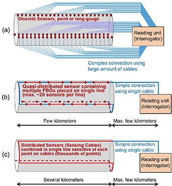
Figure 1. Schematic representation of (a) traditional discrete sensing (with one-to-one sensor connections to reading unit), (b) quasi-distributed sensing using FBGs interconnected over single line (long-gauge sensors shown in figure), and (c) distributed sensing of a large structure (modified from the slides of author's university course CEE 537 Structural Health Monitoring and [7]).
Download figure:
Standard image High-resolution imageLong-gauge FOSS enabled accurate measurements in inhomogeneous materials (e.g. concrete) and provided greater spatial coverage per unit sensor, which in turn enhanced sensors' capability to detect damage but also enabled coverage of large volumes of structure with relatively limited number of sensors, and thus made possible global-scale SHM that provided information on the structure as a whole (and not on only a small, local, part of it, e.g. see [2]).
Distributed FOS are practically cables sensitive to strain, temperature, or vibration at every point along their lengths. They enabled monitoring of a 1D fields of these parameters along the entire instrumented lengths of structures. They provide large number of measurement points, extensive continuous spatial coverage of structure that tremendously enhances the capability of damage detection, and simplify installation and connectivity (see figure 1). Distributed FOS enabled SHM at fine grain integrity scale for all types of structures but were proven particularly efficient in the cases of very large structures such as dams, tunnels, long bridges, oil and gas infrastructure, etc [1, 2, 6].
Current and future challenges
Depending on physical principle and hardware components, various types of FOS technologies feature different challenges. Here we focus on those related to quasi-distributed and distributed sensors.
For FBG sensors the main challenge is thermal compensation. FBG sensing element is simultaneously sensitive to both strain and temperature, and thus each strain sensor requires two FBG sensing elements—one coupled with structure, to measure strain, and additional, kept uncoupled, for thermal compensation. The use of two sensing elements per sensor increases the cost, limits the number of sensors that can be placed on the same line, and affects accuracy of strain measurement.
For Brillouin technologies the challenges are dynamic measurements and relatively long length of spatial resolution. Spatial resolution is the length of distributed sensor over which the measurement is averaged. It can be considered as equivalent to gauge length of discrete sensors and in commercially available systems it is currently limited to approximately 20 cm. For Rayleigh technology the challenge is limited length of sensor (currently up to 70 m for commercially available systems). In addition, a common challenge for all distributed FOSS are thermal compensation and deployment that guarantees desired level of strain transfer, as they may need to be installed over lengths in range of kilometers. Best performances of commercially available FBG, Brillouin, and Rayleigh technologies are given in table 1 [7].
Table 1. Best performances of the commercially available quasi-distributed (FBG) and distributed fiber optic sensors; note that, in general, the best performances cannot be simultaneously achieved; adapted from [7].
| Property | FBG (connected in series) | Stimulated Brillouin scattering | Spontaneous Brillouin scattering | Rayleigh scattering |
|---|---|---|---|---|
| Gauge length/spatial resolution | 10 mm–2 m | 0.2–5 m | 1 m | 10 mm |
| Min. spatial sampling | ∼10 mm | 100 mm | 50 mm | 0.65 mm |
| Max. number of sensors per reading unit (w. channel switch/multiplexer) | 16 lines with ∼20 measur. points each | 16 | N/A | 8 |
| Resolution | 0.2 μ
| 2 μ
| 2 μ
| 0.1 μ
|
| Reproducibility ('accuracy') | ∼1 μ
| ±2 to ±50 μ
| ±20 μ
| ±30 μ
|
| Sensor range | −5000 μ to +7500 μ
| ±10 000 μ
| ±10 000 μ
| ±15 000 μ
|
| Max. sensor length | Several km (one line) | 50 km | 25 km | 100 m |
| Temperature compensation | Needed | Needed | Needed | Needed |
| Measurement time or frequency | 0.5 MHz | 10 s to 15 min. | 4–25 min. | 250 Hz. |
Besides these technology-specific challenges, a major common challenge of all types of FOS is elevated cost. Cost of FOS technologies is on average higher than the cost of the traditional sensor technologies, which makes them less economically competitive despite of their sensing advantages. The main reasons for elevated cost are the use of expensive components in sensors and reading units to achieve high quality of technology and the associated manufacturing processes. Nevertheless, while the cost of FOS did not decrease over the last quarter of the century, it did not increase neither (despite usual inflation) and the difference in cost compared with traditional sensors has been steadily decreasing. This trend is expected to continue in the future as the acceptance in industry and number of real-world SHM applications continue to grow.
Advances in science and technology to meet challenges
In order to address the challenge of thermal compensation of FBG sensors, in recent years researchers focus on finding compensation functions applied to the measurement and compensation FBG sensing elements (e.g. [8–10]). While this improves accuracy of measurements, it does not reduce the number of FBG sensing elements per sensor. To circumvent this challenge and reduce the cost while increasing the number of FBG sensors per channel, new research on multi-core fiber FBG sensors is ongoing in parallel (e.g. see [11, 12]). Here the main idea is to use optical fibers with more than one core embedded in cladding (e.g. 4 or more), and inscribe multiple FBG sensing elements along each core, which will increase the number of sensing points per line and enable direct monitoring of curvature, while keeping the number of thermal compensation sensing elements limited.
To address the challenge of dynamic monitoring for Brillouin-based sensing systems, solutions were looked for at the level of reading unit hardware and signal processing scheme. For example, the frequency of optical oscillator in the Brillouin Optical Time Domain Reflectometer (BOTDR) reading unit can be set to acquire backscattered power at the maximum slope of the gain spectrum, so that all strain changes resulting in Brillouin frequency shift are detected dynamically as changes in amplitude [13]. Another example, related to Brillouin Optical Time Domain Analyzer (BOTDA), is to replace time-consuming frequency sweeping with a single pump pulse by using an optical chirp chain probe wave generated by a fast-frequency-changing microwave [14]. Similar, spatial resolution can be reduced to millimeter level by scientific breakthrough implemented at reading unit level. For example, differential pulse-width pair BOTDA uses two pump pulse signals with slightly different pulse widths to get a differential Brillouin gain for strain measurement [15]. Another example is the Brillouin optical correlation domain analysis where the interaction of two identically frequency-modulated counterpropagating continuous waves (CW) is used [16]. Finally, research shows that thermal compensation in distributed sensors can be achieved in single optical fiber sensor by implementing advanced optical decoding schemes such as Brillouin beat spectrum in large-effective-area fibers [17]. To increase the range of Rayleigh-scattering based sensors, the strength of signal at the end of the fiber should be boosted, e.g. using various optical amplifiers, Kerr effect, rectification of distorted signal, or other optical techniques [18].
Finally, decreasing the cost of FOS can be obtained by increasing the demand for FOS that would stimulate competition and require mass-production and automatized manufacturing. This would require further research in extension of durability and long-term reliability of FOS, simplification (semi-automatization) of installation, and creation of reliable algorithms for an automatic long-term data analysis.
Concluding remarks
FOS revolutionized SHM by providing durable and long-term reliable sensing, as well as novel long-gauge and distributed sensors, which in turn enabled instrumentation of large volumes of structures and opened doors for SHM at global and integrity scales. Their development started in 1970's and their market readiness was achieved throughout 1990's and 2000's [7], when they also energized industry and sparked creation of numerous new companies. Today, FOS technologies are well-established, mature, and widely implemented in a range of SHM applications. Nonetheless, as shown in previous subsection, FOS continue to be an important research topic of interest, aiming to overcome some of their challenges and improve their performances (e.g. [8–18]). In addition, great efforts are put in widening their applicability, e.g. for high temperature monitoring, corrosion, intrusion, etc (e.g. see [19, 20]). Progress in material science and manufacturing technologies, accompanied with developments in big data analytics (machine learning), have potential to greatly extend the durability and long-term reliability of FOS to several decades and provide algorithms for reliable data analysis of long-term data and especially for identifying slowly evolving degradation phenomena. Thus, it is certain that FOS will play important role in SHM in the decades to come.
2. Acoustic emission (AE) technologies for next generation SHM
Leonard J Bond
Department Aerospace Engineering and Center for NDE, Iowa State University, Ames, IA, United States of America
Status
AE is the basis of an important class of passive nondestructive testing (NDT) and SHM methods. An AE event is the spontaneous emission of sound pulses from materials subjected to external stress, typically applied as a result of a loading process and a sudden relaxation of stresses, most commonly forming a crack or other degradation, within the material. These events produce wave-fields that are, initially a combination of longitudinal and shear waves, and which interact with the structure to give Rayleigh, Lamb and other plate modes, which depend on the material and geometry, and which are analogous to the waves generated by an earthquake [21]. Such AE monitoring is simple in concept, however its capabilities were grossly oversold in the 1960's and '70's. Since then the science base has been significantly expanded, including understanding source mechanisms [22]. The parameters that influence AE and its measurement are now well established [23], and it had been demonstrated with many applications [24]. One major development was 'modal AE' where the physics of AE generated become linked to analysis of Rayleigh, Lamb and other plate waves [25]. In recent years two forms of commercial instruments have emerged, those which just record AE events and those which provide AE monitoring combined with guided ultrasonic wave (GUW) measurements, in which pulsed piezoelectric transducers are used in a sparse ultrasonic array [26]. AE in its two forms has now been successfully demonstrated in a diverse range of applications. These generally form two families of problems, and these are (i) proof tests and periodic inspections, involving a few hours of testing, such as with a small pressure vessel or laboratory sample loading, and (ii) long-term SHM of structures, which may last weeks or months, and these are complicated by challenges of transducer coupling, mounting, power supply and both sensor drift and damage [26, 27]. Early demonstrations of AE included applications for the NASA Space Station [28] and crack growth monitoring of a dissimilar metal weldment at the Limerick Unit 1 Nuclear Power Plant [29]. This work formed the basis for the first American Society of Mechanical Engineers (ASME) SHM code case. It has also been used for composite materials and concrete structures, such as bridges and buildings, including a demonstration with loading taking a bridge structure to failure [30]. AE most commonly uses piezoelectric sensors, but studies also use micro-electromechanical systems (MEMS) [31], sol-gel and optical fiber sensors [32], in some cases integrated into composite materials. AE, including when integrated with GUW, are one family of SHM sensors which can give data to be combined with other parameters that include temperature and stress [33]. In all cases AE requires continuous monitoring, and detection of what can be low amplitude signals, utilizing a sparse transducer array, that generates voluminous quantities of data, which require analysis, in near-real time, to give anomaly/crack locations, growth rate and a physical size that can be used in prognostics analysis. These location and defect data need to be a characterization that can provide locations for localized inspection and resulting data that can be integrated with that from periodic NDT measurements. AE has now been used for detecting and monitoring damage in different structures and, for some applications, it has earned a reputation as one of the most reliable and well-established of SHM monitoring techniques. The AE measurement process is shown in the schematic figure 2. It is an efficient and effective technology used for fracture behavior and fatigue detection in metals, fiberglass, wood, composites, ceramics, concrete and plastics. It can also be used for detecting faults and pressure leaks in vessels, tanks, pipes, as well as for monitoring the progression of corrosion in welding. There have been applications in numerous engineering fields, including manufacturing, civil, aerospace, nuclear and material engineering.

Figure 2. AE measurement process: source, sensor, signal capture and analysis, source location and characterization.
Download figure:
Standard image High-resolution imageCurrent and future challenges
For short term proof tests and periodic inspections, which can range in time from hours to at most a few days, using mostly commercial systems with an array of AE sensors, the general concepts and fundamental wave propagation, Rayleigh waves on thick material, and typically an assembly of guided (Lamb) modes in thinner plates [21], are well established. The challenges or opportunities are to be found with: (i) better sensors, that give improved signal-to-noise, (ii) for new problems, better matching of transducer bandwidth to structure-guided wave (GW) propagation characteristics, (iii) optimization of sensor sparse array numbers and locations to ensure coverage and (iv) new and improved data processing. This can include a variety of AI tools, particularly to match data characteristics to AE event signatures [34]. For long-term monitoring the initial problem, particularly on large structures, exposed to natural forces and the effect of weather (rain, snow, ice, wind, temperature), is to provide a system with adequate robustness, power supply for pre-amplifiers, coupling of sensors to the structure and reliable data transmission. Both battery and wired/wireless technologies have been deployed. However, for example, for sensors used on an off-shore oil rig, surviving the first storm is a critical benchmark! When given a robust sensor system that is well designed, and deployed, the biggest challenge is then data capture, recording and near-real-time analysis. To be useful an AE system must give reliable identification of both feature size and degradation growth and the location of these cracks or corrosion, that can then enable more complete characterization using conventional NDT tools. For AE—GUW systems these have the same fundamental system issues as already mentioned. In addition, it is necessary to optimize AE-GUW transducer parameter selection and to match these to the structure wave propagation characteristics. An AE-GUW system is significantly different, in terms of transducer characteristics, from those used in GW generation, that does not incorporate an AE capability [35, 36]. There are a diverse range of types of AE sensors: including piezoelectric, optical fiber and MEMS. Each type has its own detection modality, as well as bandwidth and sensing mechanism. The output signals cannot be simply treated as voltages that can be compared. Much work is needed to better understand the inter-relationships of the data from these various classes of sensors. In the case of optical fiber systems, that are seeing increased use in composite structures their impact on the mechanics of the structure, as well as the cost of such instrumentation remain challenges. Across all classes of AE measurements it is critical to understand the material—wave propagation and attenuation characteristics, in plate mode propagation, and required sensor spacings to ensure needed coverage and sensitivity (either near a local feature or for global deployment). With whatever array is implemented it is then necessary to ensure adequate signal digitization (A/D) in amplitude and time, bandwidth and sensitivity for these transient phenomena and then data management (storage and information extraction). In quantification of AE SHM data (i.e. crack or other anomaly characterization) that can be integrated with a characterization obtained during periodic inspections, using ultrasonic testing (UT or other nondestructive evaluation (NDE) methodology there is a need to provide a common metric or degradation characterization for use in prognostics [37]. Finally, for some SHM implementations, such as those in nuclear power plants, there is a lack of regulatory relief when is SHM installed. Periodic NDT is still required to be performed, even when SHM data are available.
Advances in science and technology to meet challenges
In SHM, including AE and AE-GUW, it has seen less implementation than may in the community would have hoped [37]. There are three critical issues: (i) sensor selection, (ii) system integration and (iii) data analysis, in near-real-time and sensitivity, to give characterizations that can be integrated with that given by periodic NDT inspections. Many of the major application areas have faced challenges: in nuclear power SHM is routinely used for rotating machinery [38], but its use for passive structures is more limited. Developing the science, instrumentation and data processing to enable SHM/AE measurements to reliably provide metrics that can be used in prognostics (remaining life) assessments is still challenging. In terms of instrument sensitivity for a contact piezoelectric sensor, which gives the highest sensitivity among the various transducer technologies, at 1 MHz the minimum detectable displacement is 2 × 10⁻¹⁷ in units of m Hz−2 [39]. Optical fibers can be integrated into composite structures (but can cause local stress anomalies). Reducing the complexity and cost of this technology is a first step. A second is to provide enhanced sensitivity of fiber-based Bragg sensors, and establishing direct comparisons with the data given with piezoelectric sensors. With the growing interest in AE—GUW systems, although use of AE sensors as transmitters is not new, developing better understanding of the physical acoustics for the sensors, when acting as transmitters, and how these AE transducers need to be matched to structure characteristics for GUW generation and detection is ongoing. For AE-GUW better understanding of the impact of transducer spacing is needed. Establishing the relationships between the different classes of sensors that are available for AE sensing needs attention. Demonstrating performance evaluation against standard ball-drop and pencil-lead-break standard sources is ongoing. For all AE measurements the biggest challenge is in signal processing, which is always a key problem in damage assessment of components and materials. Much work is needed to improve parameter analysis and waveform analysis in AE signal processing. Features to be extracted, particularly when used for AE-GUW, needs standardization.
Concluding remarks
AE is one of the pillars of passive SHM, which is now being complemented by AE-GUW measurements. AE is in general good at detecting something occurring: i.e. crack growth, particularly in shorter term measurements such as pressure proof tests. Longer term AE monitoring is often faced with system resilience and robustness issues and systems that cannot adequately survive service in harsh environments. Data collection, management and processing, to give required and needed characteristics remains difficult, particularly given the poor signal-to-noise for many AE field implementations. There are opportunities for new sensor classes, but standardization of response characteristics is needed.
3. Radiofrequency (RF) sensors for SHM
Mauricio Pereira and Branko Glisic
Princeton University, Princeton, NJ, United States of America
Status
The need to detect and localize critical damage of minute dimensions (e.g. millimeter and sub-millimeter cracks) in large structures (e.g. tens and hundreds of meters) is a fundamental challenge in SHM of civil infrastructure. Commonly used sensors, such as point strain sensors, are unable to reliably detect, quantify, and localize damage at moderate distances from their installation point [40]. Unidimensional distributed or quasi-distributed sensors (e.g. based on fiber optics) ameliorate spatial resolution but still suffer from limited spatial coverage. These limitations motivated the development of novel strain sensors with increased spatial resolution and coverage, such as two-dimensional strain sensors [41]. A subsequent research advancement would be to create innovative three-dimensional distributed sensors. However, most of these novel sensors require tethering for power, data acquisition (DAQ), transmission, and storage, leading to costly and labor-intensive installation and maintenance processes [42], especially if sensing throughout the material volume is desired. This makes difficult the universal deployment of tethered sensors in large structures. To achieve widespread application of SHM to civil infrastructure, low cost, scalable, high-resolution, pervasive monitoring throughout (and sometimes beyond, for circular construction) the operational life of the structure is needed [43]. An approach to achieve this ideal scenario is the deployment of wireless sensors that bypass the need for tethering and simplify the installation process, with the potential of pervasiveness and scalability [44]. A major challenge with wireless sensors concerns its powering, typically provided by limited-life batteries. An alternative approach is the use of passive RF identification (RFID) sensors that are powered by an external exciter. RFID-based sensors are low cost, can achieve high granularity, and operate over the service life of the structure [45]. While RFID was primarily designed for asset tracking, it is possible to design its antenna so that its circuit and/or communication channel properties are correlated with quantities of interest for SHM, such as strain, humidity, and temperature, effectively rendering them RF sensors. For example, a common method is to measure the resonant frequency shift in the circuit as the antenna deforms. Significant research was devoted to the development of RF-based sensors for SHM, with accelerated pace since the mid-2000's [45], corrosion [46], displacement [47], and cracking. For example [48], provides wireless millimetric crack movements based on a piezoelectric sensor (see figure 3). Sensing environmental factors, such as temperature [49] and moisture [50], is also possible and fundamental for the long-term monitoring of civil infrastructure so that damage can be distinguished from environmental effects.

Figure 3. Passive RFID-based masonry cracking sensor proposed by [48].
Download figure:
Standard image High-resolution imageCurrent and future challenges
Challenges to the pervasiveness of current RF sensors are the limited reading range and its discrete nature. An exciter must be present nearby because passive RF sensors require an external power source. The distance between the sensor and the exciter can range from a few centimeters to several meters depending on the frequency of operation. However, high-resolution sensing requires high-frequency RF sensor, which limits both how far the RF exciter can be and how deep in the material the sensor should be embedded [42, 45]. The limited reading range can also cause communication, sensing accuracy, and reliability issues, and must be carefully investigated. One emerging approach to improve reading reliability is the deployment of multi static configuration systems in which several readers are available, or the deployment of multiple RF sensors [45].
Current RF sensors typically provide point measurement, and thus cannot detect damage away from their position or from the reader-sensor electromagnetic wave path. This is addressed by the deployment of multiple sensors, with thousands envisioned for some applications. However, the deployment of thousands of sensors will generate a data throughput issue because of the current RF-sensing paradigm, based on several sensors to few, usually one, readers topology. This is a concern for wireless sensor networks (WSNs) in general. An approach to address this issue in WSNs is to leverage the embedded computational power available in the wireless sensors to perform in-network data processing and damage detection, hence removing the need for data transmission to a central data processing node [42]. Thus, energy efficient embedded computation is another contemporary challenge for RF sensors.
The antenna design for RF sensors is a current challenge too, as it requires simultaneously satisfying competing requirements for communication (e.g. range, robustness) and sensing (e.g. high-resolution, sensitivity) with the same antenna. Also, the RF sensor antenna is often designed to match the RF chip in a reference state, which may not occur if the chip's state depends on the structure's state, which is continuously changing due to damage or ordinary environmental changes. Furthermore, for sensors to be deployed in large quantities, they should be miniaturized to not interfere with the mechanical properties of the monitored structure, and be able to detect minute defects, but miniaturization reduces the radiation efficiency of the antenna [45] further jeopardizing reading range. Hence, miniaturization and testing under environmental influences represent future major challenges for real world RF-sensing application.
Advances in science and technology to meet challenges
Current reading range are limited by the RF sensor sensitivity, and development of integrated circuit technology is expected to aid in increasing the reading range [45]. An innovative solution to address the read range limitation is the use of RF sensors that can communicate with each other, effectively generating a sensor-to-sensor (or tag-to-tag, see figure 4) communication [51–53]. This approach meets multiple requirements for the ideal SHM, as it opens the possibility of pervasive, high-resolution volumetric sensing. Since each sensor only needs to communicate with neighboring sensors, there is the possibility of using high frequency RF for high-resolution tag-to-tag communication while maintaining material penetration by using lower frequency for tag network powering. For example [51], demonstrated the application of such an approach towards sensor tracking, with potential for sub millimeter resolution. Such emerging RF-sensing paradigm also addresses the removal of the exciter interference [54, 55].
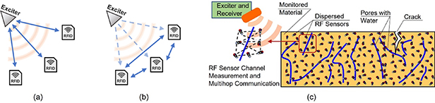
Figure 4. A comparison between (a) traditional RFID systems, (b) novel tag-to-tag RFID networks, and (c) translation of tag-to-tag RFID network in dense dispersive network of RF sensors for SHM purposes.
Download figure:
Standard image High-resolution imageAs previously mentioned, the deployment of thousands of sensors will generate enormous volumes of data. The current sensing paradigm acquires and transmits the data, but it has been shown that data transmission is one of the most power consuming tasks in a wireless sensor [42]. One strategy to address this is the use of embedded computation. Hence, performing data analysis at the sensor embedded computational core is of interest to reduce the excessive amount of data, render energy efficient RF sensors, and achieve fully automated SHM. Innovations in alternating current computing can be a pathway to enable energy-efficient embedded computing power in RF sensors [56].
Still, backscattered-based RF sensors must relate the measured channel characteristics (e.g. amplitude and phase) to the measurands of interest of SHM (e.g. displacement, humidity, porosity). Complete physics-based modeling of such phenomena is difficult, and wide variations in real-world environments and material properties may render the first-principles approach infeasible. Thus, it is expected that RF-sensing will require advanced data-driven modeling. Hence, advances in machine learning towards data driven SHM are expected to enable material characterization and/or damage detection, quantification, and localization based on RF channel characteristics. Advances in compressive sensing [57] and learned data compression [58] are also relevant for energy efficiency.
For practical deployment of RF sensors, manufacturing must be kept low cost and reliable, and miniaturization should be achieved for pervasiveness [59]. Therefore, advances in antenna manufacturing, such as antenna printing technology on various substrates, and simplified antenna design will be instrumental to the realization of pervasive RF sensor technology for real-world SHM of civil infrastructure.
Concluding remarks
The research in RF sensors for SHM purposes has been in active development since the mid-2000's and significant challenges still exist in efficient power usage, miniaturization, long-term durability, and feature extraction. RF sensors show great potential for SHM due to their lower maintenance and installation cost in comparison with tethered sensors, and especially for their potential application as large networks that can provide embedded computing and automated SHM, and enable scalable, pervasive, low-cost, high-resolution, sensing capable of addressing the fundamental antithesis of detecting minute damage over large structural volumes. The emerging paradigm change of true wireless sensing offered by RF-based sensors, which contrasts with the prevailing view of wireless sensors as the nexus of transduction, computation, and communication, creates exciting new opportunities for SHM. As RF-based dense sensor networks become truly active by employing RF channel characteristics between the sensors to interrogate the material, RF-sensors hold the potential for low-cost, long-term durability, and volumetric pervasiveness. Low-cost and miniaturization will be enabled by advances in antenna manufacturing. Advances in signal processing and machine learning hold great promise in advancing data compression, automated SHM via embedded algorithms, and data storage, as well as improved damage detection algorithms and feature extraction.
Acknowledgments
The material presented in this section is based upon work supported by the National Science Foundation (NSF) under Grant No. CMMI-2038 761. Any opinions, findings, and conclusions or recommendations expressed in this material are those of the authors and do not necessarily reflect the views of the NSF. Authors are indebted to Prof. Petar Djuric, Prof. Samir Das, Prof. Emre Salman, and Prof. Milutin Stanacevic for insights and mentorship regarding RF-sensing technologies as well as for permission to use their material in this section.
4. Cell phones
Alberto Di Matteo and Antonina Pirrotta
Department of Engineering, University of Palermo, Palermo, Italy
Status
Recent advancements in sensor and computer technologies have led to a rapid development of SHM methodologies, providing useful diagnostic tools for ensuring integrity and safety, detecting damage, and evaluating performance deterioration of civil infrastructures. Major issues associated with deployment of current SHM systems on a massive scale are prohibitive costs of sensors, installation, maintenance, cabling issues, wireless communication, power consumption, etc. To tackle these issues, in the last decade several research efforts have been devoted on the possible utilization of smartphones in SHM procedures, due to some unique features.
Modern smartphones are ubiquitous devices instrumented with various sensors such as a barometer, gyroscope, accelerometer, camera and magnetometer, and have significant on-board computing capabilities [60]. They are equipped with batteries that are charged by their users and have storage in the order of gigabytes. Moreover, smartphones are supported by mobile operating systems and wireless communication hardware that can be used for field data collection and uploading real-time data to a server via Wi-Fi and 5G networks. Clearly, these characteristics constitute an irreplaceable opportunity for developing portable and low-cost SHM systems, that could be easily implemented on a massive scale.
Notably, first studies [60, 61] on the use of smartphones for civil engineering applications, are related with pavement condition assessment, to allow for a continuous evaluation of road conditions and proper maintenance operations. Most of the existing studies in this area are focused on detecting road bumps and anomalies, while pavement roughness estimation is less investigated. Pioneering research on applications of smartphone technologies for SHM in structural engineering field was carried out in [62], where classical peak-peaking method has been tested on the frequency response function determined on the time series data recorded accelerations of smartphone devices, and in [63, 64] where a cloud-SHM method has been developed based on smartphone data, for estimation of cable force test and natural frequencies of Xinghai Bay bridge in China. Further, the versatile usage of smartphones in monitoring a full‐scale building was explored in [65] where an unconventional idea to condition monitoring of a full‐scale building was presented considering the Millikan library at California Institute of Technology. Since these initial studies, additional research efforts have been devoted to the assessment of smartphone technologies for SHM applications, comparing the reliability of this equipment to standard monitoring set-up, or focusing on novel procedures or algorithms adapted for issues pertaining to these devices. In this regard, recent comprehensive literary review can be found in [60, 66, 67]. Notably, most of the studies in the literature have focused on the use of accelerometers embedded in smartphones as a tool to monitor structural conditions. In principle, however, other sensors may be employed if necessary. For instance, recently smartphone cameras have been used to measure displacements and perform structural modal analysis [68, 69]. It is worth mentioning, however, that the research on this topic is still in its infancy, and additional efforts are required to lead this technology to a more mature stage.
Current and future challenges
To date, studies on smartphone-based SHM techniques are mostly focused on application to bridge condition assessment [70, 71], where the use of smartphone has shown to be a promising alternative to up-to-date SHM technologies. In this regard, some of the main issues related to application of smartphone for buildings SHM is associated with the deployment of these devices in buildings. These includes [65]:
- accurate location determination within the structure;
- possibility to rigidly connect the phones to a number of significant points on the structures for a reasonable amount of time, to acquire sufficient data for structural dynamic identification;
- determination of devices' orientation and height (floor level).
On the other hand, some of these issues can be circumvented in bridge health monitoring. In this case, in fact, vibration data collected via the embedded sensors in common smartphones can be geo-localized using the global positioning system (GPS). Further, cell-phone orientation and height do not represent and issue, since generally only bridge's vertical accelerations data are required, while phones' height is usually constrained by the geometrical configuration of common bridges.
In any case, however, accuracy and reliability of sensors, especially MEMS accelerometers, in common smartphones, represent to date the major obstacle to the development of this technology [71, 72]. The resolution of smartphone acceleration measurements is not as precise as those of conventional sensors, and different generations of smartphones provide different acceleration measurement resolutions, which in some cases may not be precise enough to capture smaller and ambient vibration data. For instance, some Samsung models and the iPhone 6 incorporate an InvenSense MEMS accelerometer model MPU-6500 with sensitivity 16 384 LSB g−1 and output noise level of 300  [65]. For comparison, note that in [73] MEMS accelerometers M-A351 by Epson have been specifically used for SHM purposes, with sensitivity of 16 666 LSB g−1 and a much lower output noise level of 0.5
  . In this regard, some further data on MEMS smartphone characteristics are reported in [65]. Notably, however, often the characteristic of the MEMS accelerometers embedded in smartphones are not provided. Thus, it is not even possible to determine MEMS accelerometers sensitivity and noise level, whose values are crucial to record reliable and accurate data. Thus, an assessment of the accuracy of the recorded accelerations is generally provided by comparison with the data obtained using classical piezoelectric accelerometers, often employed in vibration-based SHM.
Further, sampling frequency rate is not often constant in the same device, and generally differs in different phones. Further, smartphone data are typically corrupted by two main types of sensors faults, i.e. drift and spikes [71]. These errors seem to be strongly correlated with the phone CPU usage fluctuations. Specifically, several factors, such as heavy multitasking and input/output loading on smartphones, may lead to fluctuation in CPU usage and unstable measured signals. These clearly represent points that need to be appropriately taken into account in a post-processing phase of the data. Nevertheless, with improvements in MEMS, newer smartphone generations will provide enhanced measurement resolution, thus increasing the possibility of implementing smartphone-based SHM techniques in the future.
Finally, compared to standard implementation, using for instance fixed accelerometers on the structure connected to a single computer for DAQ, recorded signals coming from a network of smartphones cannot be generally precisely synchronized in time, and may be even subjected to missing data [74] occurring for instance as a result of failed communications or the required use of a device by the owner during the acquisition. Therefore, specific and advanced structural dynamic identification methods are needed to appropriately deal with SHM implementations based on smartphone technology.
Advances in science and technology to meet challenges
The current status of the research suggests that reliability and accuracy issues will be resolved in the relatively short term through the continuous development and advancement in sensor technology and MEMS accelerometers accurateness which are implemented in up-to-date smartphones [71].
The next generation Smart Cities will be heavily dependent on the integration of smart infrastructure with information and communication technologies and the internet of things (IoT) [60, 67]. Through IoT connectivity, smartphones have an ability to facilitate mass participation and information gathering, as illustrated by mobile applications, whose service is dependent on individual user contributions (e.g. Google Maps). Clearly, multisensory smartphone information collected using a crowdsourcing sensing approach can be an asset for intelligent decision making in smart cities [75]. Mobile crowdsensing is based on active participation of citizens in collecting appropriate sensor data using their smart devices. Over the last few years, this low-cost or no-cost data collection approach has grown considerably due to the widespread use of internet, smartphones, and mobile networks [75]. Recent studies on the use of multiple different smartphone-based data for SHM application, have demonstrated that in an average sense, signal features of crowdsourced smartphone data can more closely match estimates from a higher quality accelerometer, thus assessing the possibility of overcoming fidelity problems by aggregating heterogeneous data sets [72].
Although, crowdsourcing such data presents an opportunity to estimate the modal properties of potentially thousands of bridges, cost-effectively, there is also a need to study the synchronization problem posed by multiple sensors with independent and potentially irregular sampling properties. However, several research efforts are now devoted to these challenges and promising methods have been already presented and tested to cope with these issues [74, 76]. In this regard, pioneering approaches are nowadays based on the possibility of implementing SHM procedures using a mobile sensor network paradigm based on the use of smartphones. Clearly, while in fixed sensor networks, each sensor is dedicated to a particular point on the structure, mobile sensors can measure vibrations from multiple structures, using the same equipment, within a short time frame. In essence, a single mobile sensor can provide information comparable to that provided by numerous fixed sensors, without added cost. For instance, it has been shown that the first few frequencies of a bridge, and in some cases even mode shapes, can be detected from smartphone and vibration sensors mounted in moving vehicles [77–80]. In this regard, in [80, 81] vehicle vertical accelerations have been employed to identify the main frequencies of the Interchange 12 bridge in Dubai (UAE). In this case, the experimental set-up comprised both a single piezoelectric accelerometer (PCB-models 393B04) and an iPhone 11. These were positioned close to the central axis of the car, to record the vertical acceleration of the vehicle (Tesla model 3 2021 edition) moving over the structure several times (figure 5). These methods, referred to as Vehicle-Bridge-Interaction procedures, are an emergent and promising active field of research, aiming at overcoming issues pertaining to variables encompassing the vehicle system, vehicle route, road profile, and the vehicle velocity that undermines the accuracy of these approaches.

Figure 5. Test vehicle and the equipment used: (a) Piezoelectric accelerometer and relative setup. (b) Smartphone with a MEMS accelerometer [80].
Download figure:
Standard image High-resolution imageConcluding remarks
Modern smartphones, having significant computational power, large memory resources, built-in batteries, processor units, and a variety of MEMS sensors, offer a promising hardware and software environment for SHM applications. The onboard computational and communication capabilities, built-in sensors, and easily programmable functionality of smartphones simplifies collecting information on existing infrastructures, thus offering novel and ubiquitous structural response measurement opportunities, with extremely low initial and running costs. However, current challenges pertaining to the accuracy of the embedded sensors, today limit the vast implementation of smartphone-based SHM systems. The sensors that come standard in smartphone models were not designed for scientific applications, and accelerometers in smartphones are subject to some basic signal processing problems, which can limit overall reliability. Nonetheless, the continuous advancements in MEMS technology will lead soon to accuracy level comparable to standard devices, and recent studies have already proved the potential of SHM approaches based on the use of smartphone data, especially when part of a crowdsourcing campaign. It is therefore evident that the technology is already available, while several research efforts still need to be focused on defining novel techniques of data processing and SHM approaches specifically designed for overcoming the issues posed by the use of smartphone data.
Acknowledgments
Authors gratefully acknowledge the financial support of the Project PO FESR 2014–2020 Crowdsense.
5. Wireless smart sensors (WSSs) for SHM
Yuguang Fu1, Jian Li2, Hao Wang3 and Tu Hoang4
1 School of Civil and Environmental Engineering, Nanyang Technological University, Singapore, Singapore
2 Department of Civil, Environmental and Architectural Engineering, The University of Kansas, Lawrence, KS, United States of America
3 School of Civil Engineering, Southeast University, Nanjing, People's Republic of China
4 Palo Alto Research Center, Palo Alto, CA, United States of America
Status
WSSs have seen rapid development and wide deployment over the past two decades for SHM. They are cost-effective and easy-to-deploy compared to the wired counterparts, and hence have a great potential to achieve the promise of pervasive sensing [82]. There are several important topics/challenges for the development of WSS. For a single WSS, one of the biggest challenges is the power constraint. Recent efforts include solar/wind energy harvesting and energy-saving mechanisms for sensor operation [83]. Multimetric sensing is another important aspect, which employs various types of measurands to provide richer multiscale information for more accurate SHM. Acceleration and strain are the two most frequently adopted sensing information [84]. In addition, edge computing can transform raw data into actionable information through onboard data processing, such as signal filtering and system identification, addressing data inundation and reducing transmission workload for wireless sensor nodes [85]. For WSS networks (WSSNs), time synchronization is essential to ensure synchronized DAQ among sensor nodes. Various time sync protocols have been developed and implemented in WSSN [86]. Additionally, wireless data transmission is generally unreliable and time-consuming. A growing effort is made for real-time DAQ for WSSNs, addressing radio interference while enabling real-time applications [87]. Decentralized data processing is critical for a multi-layer WSSN, in which raw data is processed by coordination of neighboring sensor nodes to improve the scalability of sensor networks. A typical study adopting this concept is system identification [88]. As the number of networks and devices grows, efficient and secured storage and analytics of a large amount of data are necessary. Researchers have discussed using database management systems and adopting the cloud infrastructure as scalable access to data visualization and analytic platforms [89]. For long-term deployment, WSSNs are generally susceptible to various issues affecting their reliability. Effective and real-time sensor fault detection is crucial, which has gained a surge of research interest in various fields [90]. Nowadays, WSS is considered an essential component of the IoT networks for civil infrastructure monitoring and management. To be upgraded for this purpose, these topics are still important and require extensive efforts in the near future.
Current and future challenges
An emerging trend has been invoked to upskill wireless solutions to replace wired counterparts while still holding the advantages of cost-effectiveness and data compression in this process, especially in the context of IoT networks. To this end, the above topics should be re-examined, and challenges are identified. In the context of a single WSS, for sudden event monitoring, the monitoring system must be always-on to capture unpredictable events while avoiding depleting batteries quickly. Event-triggered sensing is a promising solution, but it may miss transient structural responses. For multimetric sensing, a more comprehensive range of sensing capabilities is desired, which requires a flexible sensing platform consisting of different interface boards that can integrate various types of sensors. The main challenge for edge computing is the limited resources in WSS. These constraints make the WSS difficult to host complex applications. On the other hand, for WSSNs, synchronized clocks do not guarantee synchronized data due to uncertainties in software processing time and low-quality crystals. The resulting synchronization error leads to incorrect SHM application results. For real-time wireless DAQ, there are two main challenges: scheduling conflicts for embedded operating systems within a WSS and radio interference for concurrent transmission among multiple WSSs. As a result, most real-time DAQs have limited network throughput. The main challenge of adopting decentralized data processing in WSSN is to optimize resource utilization among different nodes, maintain a stable multi-layer network topology, and realize reliable multi-hop communication for large-scale networks. Applying cloud computing and management to SHM brings up two major challenges: a systematic framework to handle multimetric data and practical computation techniques for handling big data analytics. For long-term deployment, although traditional signal processing techniques can detect sensor faults, significant human interventions are involved. Differentiating between the occurrence of events and errors is also a challenging issue in sensor fault detection.
Advances in science and technology to meet challenges
To address the above-mentioned challenges, several latest and significant advancements are summarized here. For event-triggered sensing, a demand-based WSS is developed to provide a universal solution [91] (figure 6), in which a programmable event-based switch is designed to automatically turn on/off a high-fidelity sensor platform without missing data. Advances for multimetric sensing include developing sensor boards to integrate high-sensitivity acceleration and strain, GPS sensor, pressure sensor, and capacitance-based sensing skin for crack monitoring [92]. The state-of-the-art wireless sensors can achieve resolution of <10 μg for acceleration measurement and <1 μ for strain measurement. In the case of edge computing, efforts are devoted to the co-design of hardware, software, and algorithms, such as the dual-core Xnode supporting preemptive multitasking [93] and lightweight onboard reference-free displacement estimation [94]. In the scope of WSSNs, for time synchronization, a two-stage approach is developed through both linear and nonlinear clock drift compensation and resampling to achieve 30 μs accuracy in data synchronization [95]. Furthermore, an improved version, called post-event time synchronization, is developed to reduce the latency of sudden-event monitoring to around 0s, compared with around 4.5 s of state-of-the-art solutions [96]. For real-time DAQ, a staggered time division media access (TDMA) is developed to enable high-throughput wireless acquisition. Subsequently, an adaptive TDMA supported by preemptive multitasking and real-time time synchronization is proposed to increase the throughput of up to 115 kbps [97]. To improve decentralized data processing, a power-optimized and reprogrammable system is developed, capable of remotely specifying and optimally allocating sensor nodes' computational operations on the fly [98]. In addition, multi-hop radio transmission is carefully handled by slot segmenting scheduling and multichannel data communication algorithm [99]. Note that, the radio transmission distance is varied in different sensor platforms, and 1 km line-of-sight distance is achieved in several next-stage wireless sensors. Multiple frameworks of domain-specific cloud platforms for SHM have been proposed, such as a cyberinfrastructure platform for SHM, adopting bridge information modeling and NoSQL database, and a railroad bridge monitoring framework implemented with time-series and relational databases (figure 7) [100]. For long-term reliable deployments, hardware improvement (e.g. sensor board) and software advances (e.g. reliable network operation) should be achieved. The continuous rise in computational power and demonstrated efficacy in various fields motivates deep learning to minimize human intervention [101].

Figure 6. Real-time sudden-event monitoring system using Xnodes, containing on-demand sensing prototypes, real-time time synchronization, and real-time data acquisition.
Download figure:
Standard image High-resolution image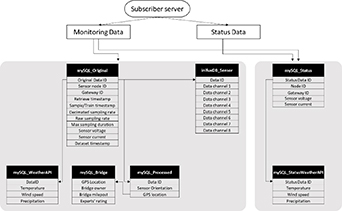
Figure 7. Data distribution from the sensor network to MySQL (relational database) and InfluxDB (time-series database) [100].
Download figure:
Standard image High-resolution imageConcluding remarks
WSSs are important measurement technologies for SHM, with the advantages of low cost and easy deployment over the wired counterparts. Through research and development, WSS has been gaining momentum to release its full potential for civil infrastructure monitoring and management. The main topics/challenges for WSS development include sensing scheduling, multimetric sensing, edge computing, time synchronization, real-time DAQ, decentralized data processing, cloud computing/management, and long-term reliability. Addressing these challenges is essential to upskilling the functionalities of WSS as a critical component of IoT networks for civil infrastructure.
6. Sensing skins
Simon Laflamme1 and Filippo Ubertini2
1 Department of Civil, Construction and Environmental Engineering, Iowa State University, Ames, IA, United States of America
2 Department of Civil and Environmental Engineering, Perugia, University of Perugia, Perugia, Italy
Status
Sensing skins emerged from advances in conductive polymers and flexible electronics that induced sensors with the necessarily compliance to be deployed over large and sometime complex geometries, whether they are deployed through adhesion or direct painting. A key sensing principle is that local deformations are transduced into a measurable state. Often, this state is either electrical resistance or capacitance, but can also be chromatic, piezoelectric, or resonant features [102]. The example of a polymer capable of transducing strain into a measurable change in capacitance is shown in figure 8(a). It consists of a soft elastomeric capacitor, here measuring 75 mm × 75 mm, constituted by a layered structure forming a parallel plate capacitor [103].
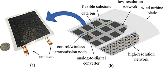
Figure 8. (a) Picture of a soft elastomeric capacitor used to constitute a sensing skin [103], and (b) example layout of sensing skin used to monitor a wind turbine blade (adapted from [104]).
Download figure:
Standard image High-resolution imageThe popularity of sensing skins is mostly attributed to the biomimicry of biological skins, where the intent is to enable localized sensing over a global area. This in essence creates a very dense sensor network than can be deployed over strategic locations of the monitored structure to extract high-resolution measurements. Figure 8(b) conceptually illustrates an integrated sensing skin system used to monitor strain on a wind turbine blade [104]. Here, the layout consists of an arrangement of soft strain gauges with different resolutions. The sensors are deployed through a flexible substrate sheet with embedded analog-to-digital converter integrated circuits. A data bus carries digital data to a wireless transmission node for further processing.
A sensing skin-based measurement strategy is ideal to discover local damages, for instance cracks, compared with traditional solutions that would be too spatially localized to conduct the task reliably or within an acceptable level of confidence. It can also be used to reconstruct strain fields over large surfaces to understand the kinematics of deformations, useful when working with digital twins or to simply detect abnormal deformations. Examples of sensing skins developed for SHM applications include nanotube-based sheets [105], flexible electronics comprising printed resistors and integrated circuits [106], and stretchable GW sensor networks [107]. Yet, the enthusiasm for sensing skins goes beyond SHM, with many notable applications in medical and wearable sensors [108, 109]. An important promise in sensing skin technology is based on easy large-scale deployments, but there exist critical challenges impeding their widespread deployments. These challenges are discussed in the next section.
Current and future challenges
One critical challenge impeding the deployment of sensing skins is the important trade-off that exists between fabrication costs and electromechanical sensitivity. A good example of such a trade-off is in the fabrication of strain-sensitive materials based on piezo-resistivity, where materials are doped with conductive micro- or nano-particles to reach the electrical percolation threshold. Often, the conductive particles of interest are carbon nanotubes because of their ultra-high electrical conductivity. These yield substantial piezo-resistive properties using low concentration levels, yet they are expensive to acquire and difficult to mix, resulting in important fabrication costs. Conversely, carbon black particles can be adopted for their low costs and ease of dispersion, yet they yield low piezoresistive properties and require large concentration levels.
Another challenge is in the obtention of necessary mechanical and environmental robustness to ensure long service life. Mechanical robustness may be provided through mechanical compliance, for instance by using highly stretchable polymer matrices that can sustain large local deformations induced by cracks. However, the use of stretchable substrates also requires stretchable interconnects, which further complicates the fabrication process [110]. Alternatively, the compliance is sometime limited to the use of a flexible, non- stretchable substrate with the intent to transfer materials damage to the sensing skin based on the designed sensing principle, as done in [106]. Environmental robustness is often overlooked for sensing skin technologies at an early development stage yet requires important considerations when using polymer substrates designed to be left exposed in harsh environments. This can be done by updating designs with necessary micro- or nano-particles after accelerated aging test assessments [111], or through strategic packaging.
Importantly, sensing skin technologies need to be deployed in the form of integrated systems capable of sensing and interpreting useful information leading to a decision system. The example of an integrated SHM system is shown in figure 9. A sensing skin is fabricated from individual soft elastomeric capacitors deployed onto the welded connection of a full-scale bridge girder with some of the sensors folded over the corner (figure 9(a)). Data collected from the sensors were fused in a crack growth index (CGI) and assembled in the form of CGI maps. The CGI is a single value that relates proportionally to the fatigue crack size, as plotted in figure 9(e). Figures 9(b)–(d) report the CGI maps for a fatigue crack that grew from an initial location (figure 9(c)) to a final location (figure 9(d)), exhibiting a clear change in the CGI maps with the yellow color (higher CGI values) indicating the crack location. In this particular application, the sensing skin was capable of detecting a minimum crack length of 0.28 mm. On an electronics level, this technology requires further integration, including a polymer substrate that would be common to all sensors, printed interconnects instead of hard wires, and integrated (possibly flexible) DAQ.
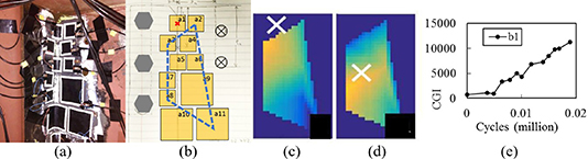
Figure 9. (a) Picture of sensing skin installed on a steel girder connection; (b) schematic of the sensor configuration, with the red 'x' showing the starting location of the fatigue cracks and the dashed blue line showing the location of the CGI map; (c) CGI map, initial crack location (white 'x'); (d) CGI map, final crack location (white 'x'); and (e) plot of CGI versus fatigue cycles relating to fatigue crack size (adapted from [112]).
Download figure:
Standard image High-resolution imageAdvances in science and technology to meet challenges
From the discussion on current and future challenges, the following advances in science and technology would be necessary in empowering sensing skins for SHM applications. First, improved fabrication and integration techniques for conductive nano-particles, in particular carbon nanotubes, must be developed to decrease their costs and facilitate the fabrication of sensing skins at large scales. The field of materials science has been quite active at working in this direction, and important advances should be expected in the near future [113]. Second, manufacturing techniques enabling the large-scale productions of sensing skins must be researched to produce sensing systems of required mechanical and environment robustness. This includes the integration of flexible interconnects, and techniques to join flexible, stretchable, and hard substrates (e.g. hard wires linking to an external DAQ system), which is of great interest to researchers in the field of flexible hybrid electronics [114]. To do so, promising techniques could be developed leveraging advances in additive manufacturing (AM) and could also be available in the near future [115]. Third, perhaps more futuristic, is the need to produce completely autonomous sensing skin systems that would also include flexible DAQ and transmission systems, as well as on-board processing and power harvesting capabilities. This would require important cross-disciplinary work integrating knowledge in materials science, industrial manufacturing, electrical engineering, SHM, in addition to the application domain expertise to optimize the design of the dense sensor network forming the skin and its location in field deployments.
On a high-level perspective, it is important for the field to join efforts in producing several field demonstrations and generating data to convince the various stakeholders of the usefulness of sensing skin technologies. Ideally, these applications would successfully link sensor data to decision systems, for example condition-based maintenance scheduling. It is only through these examples that one would be capable of understanding the potential financial gains in using these densely distributed networks. Because this is also true for any other SHM system, it will also be important to identify key SHM applications for which sensing skins would be substantially advantageous to other SHM technologies. An example is their use to discover new fatigue cracks, whereas other existing sensing solutions are too localized to be capable of such.
Concluding remarks
To conclude, sensing skin is an exciting and promising SHM technology, because it has the potential to emulate biological skin to allow for the local detection of damage and other states of interest over very large surfaces. While researchers focusing on sensor development within the field of SHM have already proposed and demonstrated interesting sensing skin technologies with groundbreaking potentials, there still exist important challenges before we see these dense sensor networks deployed in the field, for example on bridges and aircraft airframes. Some of these challenges have been discussed, and it is anticipated that current and future research will help meet these scientific and technological challenges in the near future. However, it is only through strategic integration of cross-disciplinary expertise and technically and financially convincing field demonstrations that sensing skins will be truly empowered.
7. Patch antenna sensors for surface strain measurements
Yang Wang
School of Electrical and Computer Engineering, Georgia Institute of Technology, Atlanta, GA, United States of America
Status
Among various measurements performed on civil structures, strain is an important indicator for stress concentration and crack development. Traditional strain measurements usually rely on metal foil strain gages and fiber optical sensors. However, these sensing technologies require lengthy cables for DAQ and power supply, which increase the overall installation and maintenance cost of the whole monitoring system and limit the deployment scale. The development of wireless communication technology has facilitated more convenient application of SHM systems on large structures. A conventional wireless sensor node usually has at least an embedded processor and a wireless transceiver [42, 44]. Although the wireless sensing systems have achieved success in field deployment, the requirement of onboard battery power remains a difficulty for long-term application. Many sensor locations on a large structure may not have reliable source for energy harvesting. Even with reliable solar power, rechargeable batteries may need frequent replacement when operating in the outdoor environment.
The recent emergence of passive wireless sensors, which do not need battery or other onboard power supply, has shown promise to overcome the challenges [116, 117]. One widely investigated approach for passive wireless sensing is RFID technology. The RFID technology can offer the ability to modulate the response signal from the sensor and thus distinguish it from environmental reflection. In recent years, many passive wireless strain sensors based on RFID technology have been proposed. In particular, antenna sensors stand out for its simple configuration and low cost. The sensing mechanism relies on the fact that the electromagnetic resonance frequency of an antenna depends on its dimension. Based on this physics principle, the wirelessly identified resonance frequency shift of an antenna sensor can be utilized to estimate the strain applied on it.
In another study, a printed RFID patch antenna has been shown to measure high strain with the change of antenna gain and impedance [119]. Meanwhile, Occhiuzzi et al demonstrate the relationship between strain and electromagnetic behaviors of a meander-line RFID antenna sensor [120]. In order to reduce the size of an RFID patch antenna sensor, Yi et al propose an antenna folding technique using vias, and validate the performance of the folded patch antenna sensor by tensile experiments [121]. Multi-physics simulation coupling mechanics and electromagnetics is proposed to more accurately describe the behavior of the sensor [122, 123]. Finally, more literature review on passive antenna sensor for strain measurement can be found in survey articles [45, 124].
Current and future challenges
One need for improvement in RFID antenna sensors is to further reduce the size of the antenna patch. Yi et al propose to add slots on the top copper cladding to provide a detoured current path, the length of which determines antenna resonance frequency [125]. The passive slotted patch antenna sensor is designed to reduce sensor footprint, while maintaining the sensor operating frequency around 900 MHz RFID band. The size reduction is achieved by introducing slots on the top copper cladding to detour the surface current, the sensor size is reduced to 4.4 × 4.8 cm2, which is only half of the previously proposed folded patch antenna sensor. Mechanics-electromagnetics coupled simulation is first conducted to evaluate the strain sensing sensitivity. Extensive experiments are further performed to verify the sensor performance. The test results show that the passive slotted patch antenna sensor is capable of sensing small strain levels. The sensor can monitor not only tensile strain, but also compressive strain with the same sensing mechanism. The interrogation range test shows that the sensor can be recognized when the reader is as far as 90 in away from the sensor.
Benefiting from the smaller size of the slotted patch antenna, strain sensor rosettes made of slotted patch antenna sensors are also studied to measure an arbitrary plane stress scenario that includes two normal and one shear strain components [126]. Simultaneous resonance frequency shifts of the three antenna sensors are used to derive the three strain components (figure 10). The multi-physics simulation demonstrates that each antenna sensor has a longitudinal strain sensitivity of −771 Hz μ−1, and a transverse sensitivity of −220 Hz μ−1. Nevertheless, although the sensor can be interrogated at a distance of 90 in, it is still relatively limited for field testing in an outdoor application.

Figure 10. Multi-physics simulation of a slotted patch strain sensor rosette mounted on an aluminum plate.
Download figure:
Standard image High-resolution imageBesides RFID modulation, frequency doubling technique using a Schottky diode is another signal modulation method investigated for passive antenna sensors [127]. By doubling the backscattered signal frequency, unwanted environmental reflections are removed. The frequency doubling antenna sensor consists of three main components—a 2.9 GHz receiving patch antenna, a matching network, and a 5.8 GHz transmitting patch antenna (figure 11). The higher operating frequencies (compared with ∼900 MHz RFID) can enable sensor size reduction and strain sensitivity improvement. For interrogation, a wireless reader emits a 2.9 GHz interrogation signal to the 2.9 GHz receiving patch antenna of the antenna sensor. The matching network integrated with a Schottky diode then doubles the interrogation frequency of 2.9 GHz to the backscattering frequency of 5.8 GHz. The 5.8 GHz transmitting patch antenna finally responds with the backscattered signal to the reader.
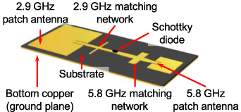
Figure 11. Frequency-doubling antenna sensor.
Download figure:
Standard image High-resolution imageValidation experiments are conducted to characterize wireless strain/crack sensing performance of the frequency doubling sensor [127]. Tensile testing shows a strain sensitivity of −5.232 kHz μ−1 and a determination coefficient of 0.9890. The strain sensitivity of the frequency doubling sensor is around five times of previously developed RFID antenna sensors. The experimental results demonstrate the potential of the frequency doubling antenna sensor for both strain and crack sensing. However, future research is needed to improve the reliability of the antenna sensor, particularly for different reader-sensor distances and interrogation power levels. In order to maximize the sensing performance, more systematic approach is required to optimize the frequency doubling antenna sensor design.
Advances in science and technology to meet challenges
Building upon the frequency doubling concept using a Schottky diode between two separate patch antennas, latest dual-band antenna technologies can be investigated to further downsize the antenna sensor size. For example, a patch-in-patch antenna configuration can contain a 5.8 GHz inner patch antenna, and a 2.9 GHz outer patch antenna. The dual-band antenna design not only reduces the overall sensor size, but also provides the capability of simultaneously measuring strain in two directions by utilizing two orthogonal polarization readings [128]. At 2.9/5.8 GHz operation, the sensor size is estimated to be 4 × 4 cm2. Once the frequency doubling methodology is verified, additional size reduction can be easily achieved by increasing the operation frequency range.
Furthermore, simulation of antenna sensor behavior requires multi-physics studies encompassing mechanical and electromagnetic modeling. Simulation efficiency is critical when striking a balance between accuracy and computational resources. Besides past frequency-domain finite-element analyses, one can investigate the performance of a multi-resolution time-domain (MRTD) scheme for electromagnetic simulation [129]. The MRTD scheme is a generalization to finite difference time domain (FDTD) method that belongs to the family of finite difference methods. While encountering problems with complex antenna geometries, the straightforward use of FDTD suffers from serious limitations due to substantial requirement on computing resources and long computing time. Utilizing scaling and wavelet functions as complete set of field basis functions, the MRTD scheme can provide adaptive gridding in both space and time, and thus, significantly save memory usage and reduce computation time.
Concluding remarks
The research field of antenna patch strain sensors is highly interdisciplinary, requiring expertise in multiple engineering domains including mechanics and electromagnetics. The development involves design, modeling, simulation, and experimental testing. Due to its very low cost at mass production, patch antenna sensor instrumentation at high nodal density can be achieved at a reasonable expense. Such novel antenna sensors have immense opportunities for various applications, since stress concentration and fracture are among the most common concerns for many engineering structures. The sensors can be used in various civil, industrial, mechanical, and aerospace structures, including both metallic and non-metallic ones. Being wireless and battery-free, future antenna sensors are expected to provide unprecedented convenience in operation, ease of fabrication, low cost, as well as high accuracy.
8. Electrical resistance tomography (ERT) and machine learning for lattice structure damage detection
Yening Shu1,2 and Kenneth J Loh1,2
1 Department of Structural Engineering, University of California San Diego, La Jolla, CA, United States of America
2 Ordered-Materials Research (ARMOR) Laboratory, UCSD, San Diego, CA, United States of America
Abstract
Cellular lattice structures with multi-scale geometrical features and designs possess excellent thermal and mechanical properties, and their impressive stiffness- and strength-to-weight ratios are well suited for lightweight engineering applications. However, defects may form during AM and when they are placed in service. Conventional NDE methods for detecting damage, such as computed tomography and ultrasonic imaging, are not ideally suited for cellular lattice structures with complex geometries. Instead, this study investigated the use of 3D ERT as an alternative NDE method, where only temporary and sparse boundary electrodes are needed to interrogate the entire structure. In short, 3D ERT utilizes boundary electrode voltage measurements to reconstruct the target's conductivity distribution. Damage such as voids and cracks in cellular lattice struts result in conductivity decreases, which can be directly visualized in the reconstructed conductivity distribution. However, the complex network of struts in 3D open cellular lattice structures and the ill-posed nature of the ERT inverse problem make conductivity reconstruction a time-consuming process. Furthermore, conductivity distributions can suffer from low imaging resolution, where small damage features within a strut cannot be accurately located. Therefore, a supervised machine learning method that utilizes artificial neural networks (ANNs) was used in the 3D ERT solver for achieving high-resolution damage characterization. This data-driven algorithm is significantly faster than conventional ERT while enabling greater accuracy of 3D conductivity distribution reconstructions. Experimental results are presented in this work to validate this machine-learning-based ERT solver.
Keywords: 3D, additive manufacturing, artificial neural network, damage localization, nondestructive evaluation, strut.
Status
Lightweight engineering has become an increasingly important focus for aerospace, naval, and automotive structures, especially when considering the goals of enhancing safety, reducing power consumption, and improving performance and safety [130, 131]. In particular, lattice structures, which can possess nano-, micro-, meso-, and macro-length-scale features to achieve unique mechanical and thermal properties, are widely employed for lightweight engineering applications [132]. They are often engineered with high stiffness- and strength-to-weight ratios that are derived from the topology of their unit cell, which can be tailored to meet specific design demands and constraints [130, 131, 133].
Despite the advantages that lattice structures have to offer, their broad use has been impeded by the difficulty in realizing their complex geometries when using conventional manufacturing processes. Traditional manufacturing methods, such as investment casting, milling, wire forming, and bonding, are limited by low-volume, high costs, and simple geometrical structures [133, 134]. More recently, advances in AM methods, such as fused deposition modeling [135], extrusion [136], and powder bed fusion [137], have enabled the realization of complex and multi-scale lattice structures. However, defects can be generated during manufacturing because of nozzle clogs or uncontrolled thermo-mechanical behaviors. While these defects may be very small initially, they can propagate when these structures are operated and loaded, where they can be subjected to design loads, unexpected impact, extreme events, and various ambient environmental effects [137]. In short, these defects can significantly compromise the performance and functionality of these multi-scale cellular lattice structures. Therefore, there is a need to characterize these defects in a nondestructive manner for ensuring optimal part quality and structural performance.
Current and future challenges
Conventional NDE methods suffer from inherent challenges when used for detecting damage in cellular lattice structures. For example, discrete sensors are difficult to be integrated into lattice structures. Even so, discrete sensors are by nature point sensors that can only measure structural response at their instrumented locations. The complexity of cellular lattice structures and the number of struts that form the structure mean that it is impractical to install sensors at every location. On the other hand, imaging methods, such as computed tomography [138], are costly, time-consuming, and require numerous projection slices to visualize and resolve internal defects. Ultrasonic methods [139] need numerous actuators and sensors, as well as complex wave propagation patterns, to overcome issues related to image artifacts and the geometrical complexity of these lattice structures.
Instead, this study investigated 3D ERT as an efficient and practical NDE method for localizing defects in complex lattice structures. In short, ERT is a soft-field imaging method that utilizes boundary electrical potential measurements as inputs to an inverse problem to reconstruct the interior conductivity distribution of a conductive body [140, 141]. Cracks or defects decrease the localized conductivity of the body, which can be identified from reconstructed ERT conductivity distribution images. Unlike conventional densely distributed sensing approaches, ERT only needs electrical current excitations and corresponding voltage measurements along the boundaries of the body, which makes this technique particularly suitable and scalable for complex cellular lattice structures. However, traditional physics-based approaches for solving the ERT inverse problem are time-consuming and computationally intensive [142, 143], even though they have been successfully used in patterned, grid-like structures similar to cellular lattices [144, 145]. Data-driven methods that could potentially output conductivity distributions in near-real-time would be more suitable for detecting damage in complex structural geometries (e.g. cellular lattice structures) and for use in high throughput manufacturing settings.
Advances in science and technology to meet challenges
Data-driven ANN techniques have garnered significant attention because of their adaptability for modeling nonlinear processes. An ANN is composed of neurons that receive and process a signal with an activation function, as well as edges that connect and transmit a signal to other neurons. The signal propagates from the first layer (i.e. input layer), through hidden layers, and to the last layer (i.e. output layer).
ANN structures that possess multiple layers with numerous neurons could be efficiently adapted to solve ERT problems with inherent nonlinearity [146, 147]. As compared to a physics-based ERT approach with one-step linearization, an ANN could reconstruct a target's conductivity distribution with higher accuracy, especially when considering the nonlinear nature of conventional ERT. Moreover, the calculation of the Jacobian matrix J in the physics-based ERT method needs the nodal potential of each FE element in each current injection scheme, which is computationally intensive and time-consuming [148].
In this work, an ERT-ANN system for reconstructing the conductivity distribution of 3D lattice structures was implemented. First, the generic structure investigated in this study is a 3 × 3 × 1 cellular lattice structure with a cubic unit cell, and the model is shown in figure 12(a). The structure consists of 64 struts, each with a length of 40 mm and a cross-sectional area of 2 × 2 mm2. A total of 24 electrodes were attached to the junctions of the boundary struts, which are marked in red in figure 12(a). To effectively apply the ERT-ANN system to the structure, the model was further meshed in Abaqus with 3440 tetrahedral finite elements. The conductivity of the undamaged structure was uniformly set as 1000 S m−1. This numerical model was used to solve the ERT forward problem to determine the boundary voltage responses corresponding to different current injection schemes. These datasets were then used for training the ANN system.

Figure 12. (a) A 3 × 3 × 1 lattice structure model with electrodes marked in red was plotted. (b) The architectures of ANN I and (c) ANN II-j are illustrated.
Download figure:
Standard image High-resolution imageSecond, the ERT-ANN system consisted of two sets of ANN structures, namely, ANN I and ANN II, was developed. ANN I was used to identify the damaged strut (i.e. with a decrease in conductivity) within the cellular lattice structure. It utilizes information from 504 boundary voltage measurements to estimate the centroid of the damaged strut j. After identifying the damaged strut j, the second ANN II-j, which corresponds to the damaged strut j, was used to localize the exact damage within that strut. In this study, only single damage cases were considered.
Training of ANN I entailed preparing datasets for an undamaged case and 5000 damaged cases for the 3 × 3 × 1 cellular lattice structure shown in figure 12(a). Damage to the strut was simulated by modeling the conductivity of a randomly selected FE element of the structure and setting it to 0 S m−1. For each case, the ERT forward problem was solved to obtain the boundary voltage response associated with a current injection scheme. They were then corrupted with Gaussian white noise with 66.2 dB signal-to-noise ratio. The normalized voltage difference (dVn) between each damaged state and the undamaged state was calculated as:
where v is the maximum absolute measurement on the undamaged structure, Vd and V0 represent voltages in the damaged state and the undamaged state respectively. Because ANN I only focuses on detecting the damaged strut instead of the exact damage location, singular value decomposition (svd) could be used on δVn for input dimensionality reduction [149]. Here, the dimension of the input depends on the number of singular values included when the ratio of variance reaches a 0.995 accuracy, and a total of 72 encoded inputs δVn svd were utilized in ANN I. The output of ANN I is the centroidal coordinates of the damaged strut.
The second structure (ANN II) includes multiple ANN structures, where ANN II-j could provide the location of the single defect within strut j, and j starts from 1 to the total number of struts (N) in the lattice structure. To train ANN II-j, 500 damaged cases, each with a unique and randomly selected single FE element defect of 0 S m−1 within strut j, were generated. The ERT forward problem was solved for each damage case (i.e. considering the entire lattice structure). Considering that all these damaged states are from the same strut j, the calculated boundary responses would be similar. Thus, svd could also be used on δVn for a more efficient input dimensionality reduction [149]. A total of 18 encoded inputs δVn svd from svd were selected to represent the 504 boundary voltages when strut j is damaged. The output of ANN II-j is the centroid of the defect element k within strut j.
The ANN architectures for ANN I and ANN II-j used in this study are illustrated in figures 12(b) and (c). With the encoded normalized voltage difference as input, four fully connected hidden layers with 2048 neurons in each layer were employed. For each neuron in the hidden layer, an exponential linear unit was implemented.
To validate the performance of the ERT-ANN system, experiments were conducted on 3D-printed polylactide acid lattice structures identical to the structure model shown in figure 12(a). The lattice structure was then coated with an electrically conductive multi-walled carbon nanotube (MWCNT)-based thin film [150]. A customized ERT data acquisition (DAQ) system was employed in this study to inject electrical current and measure boundary voltages. Two different damage states (i.e. states 1 and 2) were investigated as shown in figures 13(a) and (b). Damage states 1 and 2 were introduced to the structure by mechanically etching off the conductive MWCNT thin film at portions of strut 1 or strut 2, respectively.
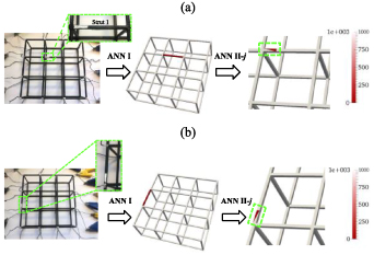
Figure 13. Experimental results and the visualization of (a) damage state 1 and (b) state 2 solved with the ERT-ANN system.
Download figure:
Standard image High-resolution imageThe effectiveness of ANN I on localizing the damaged strut was examined first. The calculated normalized voltage differences (δVn) between undamaged and damaged states were processed with svd and employed in ANN I as inputs. The predicted locations of the strut centroids, x, y, and z were stated with the true centroids of damaged struts in table 2. The image position errors1 for the two states are 0.1702 and 0.0683, respectively [151]. The predicted values were then employed in the k-nearest neighbors algorithm to find the damaged strut in the two cases. The middle figures in figures 13(a) and (b) confirmed that ANN-I was able to correctly identify the damaged strut in the lattice structure for both damage states.
Table 2. The true and predicted centroids from ANN I and ANN II in damage state 1 and state 2.
| ANN I | ANN II | ||||||
|---|---|---|---|---|---|---|---|
| x (mm) | y (mm) | z (mm) | x (mm) | y (mm) | z (mm) | ||
| State 1 | True | 39.00 | 57.00 | 19.00 | 38.76 | 44.57 | 19.73 |
| Predicted | 44.30 | 61.25 | 19.46 | 39.02 | 45.62 | 19.51 | |
| State 2 | True | 58.00 | 0.00 | 19.00 | 70.61 | −0.31 | 19.80 |
| Predicted | 56.60 | 2.27 | 19.60 | 69.55 | −0.20 | 21.06 | |
Then, ANN II-1 and ANN II-2 corresponding to strut 1 and strut 2 were then employed to estimate the specific damage locations within each respective strut. The true and the predicted x, y, and z of centroids for each state are reported in table 2, and the image position errors for the two states are 0.0276 and 0.0413. The result visualizations are shown in the right-hand-side images in figures 13(a) and (b). The results show that ANN II-j was able to correctly identify the portion of the strut where the damage occurred. Only small deviations between the actual and predicted locations were observed. Similar to before, the predicted centroids could be fed into the k-nearest neighbors algorithm to obtain the x, y, and z coordinates for the damaged element. The precision of the ANN systems is constrained by the discretized finite element. Overall, these test results validated the damage localization performance of the ERT-ANN system for topologically ordered lattice structures with low image errors.
Concluding remarks
An ERT-ANN system was proposed in this study for detecting and localizing defects, such as broken or partially damaged struts, in topologically ordered conductive lattice structures. Specifically, the ERT-ANN system consisted of two ANN structures. ANN-I was used to identify the damaged strut, while ANN-II further determined where the damage occurred within the strut. The method was trained using numerically simulated data (i.e. by considering different damage cases and calculating the boundary voltage responses using the ERT forward problem). Upon training, experiments were performed using a conductive thin-film-coated lattice structure, where damage was introduced by etching off portions of the film in different struts. The ERT-ANN system was able to correctly locate the damaged struts and accurately identified the portion of each strut that was damaged. Overall, the data-driven ERT method could utilize boundary voltages to reconstruct the conductivity distribution of complex 3D lattice structures and detect conductivity decreases due to damage such as strut breakages, voids, or manufacturing defects. Future studies will consider different damage severities as well as more complex distributed damage scenarios.
9. Smart structural materials
Filippo Ubertini1 and Simon Laflamme2
1 Department of Civil and Environmental Engineering, University of Perugia, Perugia, Italy
2 Department of Civil, Construction and Environmental Engineering, Iowa State University, Ames, IA, United States of America
Status
Smart structural materials can be defined as structural components with added functionalities enabling, for instance, self-sensing, self-healing, and self-actuating. This field of smart structural materials gained enormous popularity after the first visionary idea of transforming structural concrete into a distributed sensing system able to reveal its internal state of stress and strain [152]. Research on smart structural materials is still very active nowadays, working at bringing a truly bio-inspired revolution in construction technology and SHM to empower the automated assessment of structural materials. Benefits of self-monitoring structures are clear to the scientific community: inherent mechanical durability of the SHM system, densely distributed sensing capability, high fidelity of the measurements, and a more direct link from signal to decisions, to name a few.
Early work on smart concrete by Deborah Chung was a conductive cement-based mortar doped with short carbon fibers and the sensing principle was based on changes in volume electrical resistivity provoked by flaw generation or propagation. To date, smart concretes are fabricated using different types of nano- and micro-reinforcements (e.g. MWCNTs [153] carbon nanofibers [154], and graphene [155]), that enhance the material's electrical conductivity and piezoresistivity, yielding substantially high gauge factors (in the range from 102 to 103 [156] whereby off-the-shelf strain sensors stay in the order of 10°). This occurs at the so-called 'percolation threshold', that is, at a doping level corresponding to the material transition from being an electrical insulator to becoming a conductor (figure 14).

Figure 14. Smart concrete strain sensors doped with MWCNTs (top) and corresponding experimental percolation curve (bottom).
Download figure:
Standard image High-resolution imageResearch efforts made in the last decades have been aimed at (1) increasing the technology readiness level and (2) extending the smart self-sensing concept to different types of construction materials [157, 158]. Notable contributions concerned the development of smart bricks [159, 160] for masonry structures (reaching a gauge factor of about 500 with the ability to sense changes in strain in the order of less than 10 microstrains), smart pavements for weigh-in-motion in bridges [161] and smart anchors for prestressed concretes using ultra high performance concrete (UHPC) [162] (capable of revealing a prestress loss of a few tens of MPa within a prestressing tendon), just to mention some of the most innovative developments.
While earliest studies were mostly experimental investigations aimed at demonstrating and characterizing self-sensing properties and optimizing on an empirical basis filler content, more recent works addressed the mathematical characterization of electrical percolation and the modeling of the electromechanical constitutive behavior of the composites, with the objective of assisting the design of the materials and optimizing their properties. These models typically follow two different approaches: (1) equivalent lumped circuits models [163] and (2) homogenization models [164]. While the former class of models is particularly useful for signal processing purposes, time-dependent response being naturally included in the governing equations, the latter class is quite more powerful at establishing clear physically-based links between matrix properties, filler properties and macroscopic elastic and piezoresistive constants of the composites. Often based on analytical micromechanics approaches, homogenization methods also offer the great advantage of being inherently implementable in computational models (e.g. finite element multiphysics models) [165]. Also worth mentioning are the efforts to develop tailored measurement approaches through DC, AC and biphasic methods.
Current and future challenges
To date applications of smart structural materials can be classified into bulk, sandwich, coating, bonded, or embedded [156]. Although some full-scale applications have been already documented, research in smart structural materials has hardly exited the laboratory environment and met the field. In short, the gap from the material level to the full-scale level is yet to be filled, attributable to the open challenges and bottlenecks that still need to be tackled. These include:
- deployment, scalability and costs
- electrodes and wirings
- signal processing and environmental disturbances.
Deployment issues come mostly from the difficulty of dispersing micro- and nano-particles within structural materials' matrices [157, 158]. In cement-based materials, for instance, the use of carbon nanotubes requires a sonication of water-nanotube suspensions that is prohibitive over large casting volumes. In smart brick technology, the difficulty in substituting an existing brick with a smart one stands out as a major limitation, let alone the issue of finding a conductive functional filler that can resist high baking temperatures.
The cost of self-sensing structural materials can be substantially greater than the cost of the base material, both due to the cost of the nano- or micro-reinforcement and to the cost of production/casting, including the aforementioned issue of dispersion. This is making embedded and bonded applications, using small sensing units, far more attractive with respect to bulk, sandwich and coating methods, as it is the case of smart concrete aggregates, smart bricks for masonry (figure 15) and smart pavement sections for traffic monitoring. Cost of DAQ equipment is a limiting factor as well, but this is also valid for traditional SHM strategies based on off-the-shelf sensors, yet the steadily decreasing cost of electronics will encourage future deployments.
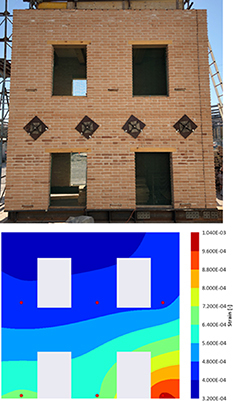
Figure 15. Full-scale masonry building monitored with six smart bricks on the façade (top) and reconstructed strain map from smart bricks' outputs using Kriging interpolation (bottom) [166].
Download figure:
Standard image High-resolution imageElectrodes and wirings still represent the greatest bottleneck for smart materials. Electrodes are hardly placed before casting and significantly complicate the fabrication of the structural components. Furthermore, they may significantly interact with steel reinforcement and pose aesthetical issues. In pavements, their embedding seems to be less critical, given that holding frames can be easily fabricated to keep the electrodes in their desired positions even before the pavement laydown. The transition to wireless seems to be easily accessible, even though the distributed nature of sensing plays against a standard wireless solution.
The response of smart structural materials to applied strain and damage is complex, fully non-linear, and strongly affected by the external environment. This is even more complicated when the stress state in the material is three dimensional. Micromechanics studies show that smart structural materials tend to be sensitive to volumetric strain while almost being insensitive to shear strain [166]. However, when electrodes are fabricated using horizontal plates, for example in smart bricks, sensing becomes essentially related to uniaxial compression due to the contact resistance contribution being in series with the internal piezoresistive contribution. The high sensitivity of smart structural materials' outputs to temperature and humidity is an additional modeling challenge that any signal processing strategy needs to take into account.
Advances in science and technology to meet challenges
The current status of the research suggests that cost and scalability issues will be resolved in the relatively short term through advances in materials science and the development of effective, bio-compatible and low-cost filler solutions and low-cost dispersion chemicals. Hybrid mixes using a small amount of nanofillers that do not pose significant dispersion problems to booster percolation of a second, larger and more easily dispersible filler should be also given full consideration. Industrial production and 3D printing [167] may dramatically reduce costs for embedded/bonding solutions, while an extensive application of bulk forms of smart sensing poses greater challenges. In the mid-range term, the cost and environmental pressure will most likely be on the electronics rather than the materials. Fabricating electronic components with bio-compatible materials will therefore become more and more important in the near future.
To finally and definitively address the electrode and wiring issues, it is of pivotal importance to develop electrode-fee sensing strategies [168] using contactless devices, for instance through electromagnetic methods. The greatest challenge here is to develop non-contact methodologies that can precisely measure material's resistivity and its small variations under strain. Such resistivity should be investigated in the bulk material and not just on the surface to achieve meaningful results with limited sensitivity to external humidity/moisture of the material. Even though in principle less attractive, externally attached measurement points with highly conductive interfaces connecting probe to sensing material seem to represent a more at hand electrode free solution, but durability of the interface may become the limiting factor.
Given the high complexity of the relationship between environment, strain, damage and electrical properties of smart structural materials, mapping structural performance/load to electrical response using mathematical models may become a formidable challenge. Here, the greatest promises come from artificial intelligence methods that have the ability to unveil complex patterns in the data and effectively circumvent through complex data mining the difficulty in interpreting the observed response based on a physical model. Nevertheless, the application of data science methods, machine learning and artificial intelligence to smart structural materials is in its infancy [169].
Concluding remarks
Transforming structures into self-assessing systems through micro- or nano-scale functionalization of their constituent materials and embedding intelligence through signal processing of smart materials' outputs promises to be the true revolution of SHM in the near future. Attaching hundreds or thousands of sensors to each monitored structure is simply not a viable option to conduct effective condition-based maintenance of our ageing structures and infrastructures. Smart structural materials, instead, can transform structures into densely distributed sensor networks, analogous to biological systems. This field of research is quite active and advances to meet existing challenges are almost continuous. However, the path to an effective technological transfer is still quite long and a paradigm shift is needed on issues regarding field deployment, scalability, costs and signal processing. Smart pavement applications, for purposes such as low cost vehicle detection and weigh-in-motion, seem to be the closest to the field and those with the highest technology readiness level. As for the other applications, we are approaching a turning point in the research where the next five to ten years are critical to actually achieve the impact that researchers have foreseen in the last two to three decades.
Acknowledgments
Research presented in this Section has been funded through a variety of European and Italian National Research Projects among which 'SAFERUP!' (European, MSCA-ITN Grant Agreement No. 765 057), 'DETECT-AGING' (National PRIN, Protocol No. 201747Y73L), 'Eco-Earth' (National FISR, code 00245) and 'SMART-BRICK' (National PRIN, Protocol No. 2015MS5L27) are especially acknowledged.
10. Smart concrete
Siqi Ding1, Xinyue Wang2, Xun Yu3 and Baoguo Han4
1 School of Civil and Environmental Engineering, Harbin Institute of Technology, Shenzhen, People's Republic of China
2 School of Civil Engineering, Dalian University of Technology, Dalian, People's Republic of China
3 Department of Mechanical Engineering, New York Institute of Technology, New York, NY, United States of America
4 School of Civil Engineering, Dalian University of Technology, Dalian, People's Republic of China
Status
As one of the most obvious manifestations of humankind's physical footprint on Earth, infrastructures carry the human civilization and progress. In order to further improve human living environment and life quality, updating infrastructures to be smart is essential. Therefore, infrastructures are at the beginning of a digitally driven revolution. During their service lives, infrastructures face slow ageing and gradual deterioration, which initiates at the material level. Perceiving the deterioration in material performance at an early stage can provide effective maintenance before serious structural failures. Therefore, self-sensing of material performance is an important paradigm for updating infrastructures with smart digital insights to enable SHM. Concrete, the most widely used engineering material for infrastructures' construction, has no intrinsic self-sensing property. The incorporation of conductive or semiconductive fillers (e.g. carbon materials, metal materials, and metal oxides) can endow concrete with the smart ability to sense stress (or loading), strain (or deformation) and damage (including crack and fatigue, etc) in itself as well as environmental actions (e.g. temperature and humidity) while maintaining or even improving its mechanical properties and durability. Since its first discovery in early 1990's, much research work has been done on the composition and preparation, measurement and characterization, sensing properties and mechanisms as well as models, and structural applications of smart concretes with different functional fillers, such as carbon fibers, steel fibers, conductive aggregates, nickel powders, carbon nanotubes/nanofibers, graphene, electrostatic self-assembled carbon nanotubes and nano carbon black/titanium dioxide, super-fine stainless wires, and in-situ synthesizing carbon nanotubes on cement/clinker/mineral admixtures/reinforcing fibers. Figure 16 shows the principles, compositions, structures, and typical sensing behaviors of smart concrete [170, 171]. Over the past three decades, smart concrete has witnessed significant advances with many innovations in both its development and applications. Compared with other sensing technologies used for SHM (e.g. optical fiber, piezoelectric material, resistance strain gauge), smart concrete is advantageous in its high sensitivity, good mechanical property and durability, natural compatibility, identical lifespan with infrastructures, easy installation, low fabrication and maintenance cost, and free of expensive accessory equipment. Well-designed smart concrete is very promising for the development of smart in-situ monitoring infrastructures, thus improving safety, lifespan, and resilience of infrastructures as well as reducing the life-cycle costs of concrete and infrastructures, and resource consumption and environmental footprint of concrete production and application. Therefore, smart concrete can provide the most fundamental material for energizing sustainable infrastructures with elegantly integrated digital insights [172, 173].

Figure 16. (a) Compositions of smart concrete and principles that a conductive network constituted by functional fillers acts as a 'nervous system' to transduce signals stimulated internally and externally to a computing center, i.e. a 'brain', mimicking human behaviors. (b) Percolation conduction mechanism and sensing mechanism under deformation. (c) Typical sensing behaviors of smart concrete under monotonic loading.
Download figure:
Standard image High-resolution imageCurrent and future challenges
Smart concrete is bringing new vigor and vitality into SHM of smart infrastructures, but there are plenty of challenges involving aspects from fabrication to applications that should be addressed in the future.
- (1)Fabrication. A major challenge in the smart concrete fabrication is how to incorporate coarse aggregates into it, which would always increase the functional filler's amount, complicate the fabrication process, and induce poorer sensing, mechanical and durability performances [174]. More efforts should be devoted to the development of advanced design and preparation methods to eliminate the aggregates' influence and to enable easy-to-process and scalable production of smart concrete with low filler dosage and sensitive and stable performances.
- (2)Measurement. The sensing signal of smart concrete (i.e. electrical signal) is easily affected by its interior polarization and the ambient temperature and humidity. The acquisition and extraction principles and methods to eliminate these influences are limited at present [169, 175]. In addition, most of the sensing signal form of smart concrete is the mechanical signal. It is essential to expand its sensing signal forms for other scenarios, such as the bonding and anchoring state between reinforcements (e.g. steel bars and FRP bars) and concrete, and durability or environmental parameters (e.g. pH value and ion concentration).
- (3)Performances. Due to the diversity and uncertainty of the compositions and performances of smart concrete, it is of great difficulty to clarify the 'sensing fingerprints' of different types of smart concrete under different loadings and environmental actions and to develop a unified mechano-electric constitutive model based on the limited understanding on conduction/sensing mechanisms [176, 177]. Meanwhile, the long-term sensing performance evolution of smart concrete is time-varied and complicated, and still lacks methods and principles for improving the stability and robustness of smart concrete as well as its performance prediction models.
- (4)Applications. One of the major obstacles that limit the scale-up applications of smart concrete is its high fabrication cost, more specifically the high cost of nano-scaled fillers. Moreover, the presence of conductive steel bars in concrete structures always causes short-circuit faults and safety concern during the implementation of smart concrete [178]. The further challenges include the design and life-cycle assessment of smart concrete-based infrastructures, the integrated methods of hardware and software for smart infrastructures, and state evaluation methods of infrastructures based on sensing signals. The industrialized and scale-up applications of smart concrete are also still facing a lack of relevant regulations and standards.
Advances in science and technology to meet challenges
The infiltration and integration of advanced science and technology with smart concrete are removing the barriers on the road to smart concrete progress, thus enabling infrastructures with digital insights (figure 17).
- (1)Fabrication. Some advanced synthetic and composite technologies/theory (e.g. in-situ synthesis, self-assembly and bionic/biological technologies, excluded volume theory) have shown great power for the scalable fabrication of smart concrete with aggregate and low dosage of fillers [172, 179, 180]. Meanwhile, the integration of smart concrete with other advanced concrete technologies (e.g. self-healing, self-powered, ultra-high performance, and sustainable concrete) can provide efficient solutions for performance improvement and functionality extensions [178, 181]. Moreover, the introduction of emerging technologies (e.g. material genome and digital manufacturing) is envisioned to enable smart and standardized fabrication of concrete [182].
- (2)Measurement. The development of novel testing and DAQ techniques coupled with data extraction and optimization algorithms are important to obtain refined and multi-level sensing signals. Electrical impedance tomography technique can provide more abundant information than conventional resistance/voltage measurement [174]. Non-contact testing or acquisition techniques of sensing signal can decrease its losses in long-distance transmission. Using circuit design (e.g. AC and compensation/differential circuits) and signal processing algorithms (e.g. blind source separation method), the polarization and environment effect can be decoupled [169, 175].
- (3)Performances. The combination of laboratory (various loading conditions, accelerated tests) and field tests, associated with conduction/sensing theories, microstructure analysis, and numerical simulations (e.g. multi-field and multi-scale) can be used for establishing unified physical model of sensing performances. Besides, extension research on long-term sensing performance evolution would provide inspiration for further understanding and tailoring sensing performances and building performance prediction models [183].
- (4)Applications. In addition to the bulk form, novel application forms of smart concrete (e.g. embedded, coated, and sandwiched forms, small size sensors/products, prefabricated members, and cast-in-place nodes) can reduce the cost due to its deployment only in structural key positions and replaceable features, address the steel bars' effect and safety issues, and protect/strengthen the structures [184, 185]. The combination of structural principles with the fusion of sensing information obtained by smart concrete with other sensing techniques can provide possible solutions for the derivatization of digital twin technology that in turn guides performance evaluation and design of smart concrete-based infrastructures [186]. Finally, the integration and design methods, state evaluation methods, life-cycle assessment, and formation of regulations and standards for smart concrete-based infrastructures can be promoted by extensive and long-term practical applications [161, 187].

Figure 17. Smart concrete-based infrastructures with digital sights.
Download figure:
Standard image High-resolution imageConcluding remarks
The failures of infrastructures built with concrete are inevitable during their service because of concrete performance degeneration and external environment action. Therefore, concrete and its infrastructures are in a state of entropy increment, i.e. availability loss. Smart concrete is an advanced material for tackling this issue because it can provide the relevant information of availability loss and guide the implementation of preventive measures. This benefits from smart concrete's self-sensing behaviors that can be changed appropriately according to the external loadings and environment actions. The state information of concretes can therefore be monitored through measuring their electrical properties. Functional fillers generate the sensing 'neural' network of smart concrete, which give infrastructures the 'gene' that enables smart in-situ monitoring digital insights. Such in-situ monitoring ability allows the assessment of service status of infrastructures as well as guides the design and maintenance of infrastructures, thus enhancing the infrastructures' safety and resilience, prolonging the infrastructures' lifespan, lowering life-cycle costs of concretes and infrastructures, and reducing the resource and energy waste as well as environmental pollution (especially carbon dioxide emission). Therefore, smart concrete is promising multifunctional engineering material for energizing the sustainable development of infrastructures for shaping and cementing human civilization.
Acknowledgments
The authors would like to thank the funding offered by the National Science Foundation of China (Grant Nos. 51978127, 52178188 and 51908103), the China Postdoctoral Science Foundation (2022M710973 and 2022M720648), and the Fundamental Research Funds for the Central Universities in China (Grant No. DUT21RC(3)039).
11. Smart textile-reinforced concrete structures
Yiska Goldfeld
Faculty of Civil and Environmental Engineering, Technion-Israel Institute of Technology, Haifa, Israel
Status
Textile reinforced concrete (TRC) technology enables the development of durable, efficient and environmentally friendly structural elements with self-sensory capabilities. Generally, the technology of TRC combines high strength concrete matrix reinforced by a biaxial textile mesh, which is usually made of alkali resistant-glass, carbon, or basalt rovings. The high tensile strength of the rovings and their high resistance to corrosion enable the construction of light, durable and optimal 2D and 3D thin-walled structural elements (e.g. [188–190]). The reduction of the environmental impact associated with the shift in construction towards this type of thin walled TRC structures and the potential contribution to the sustainability of the built environment are among the main advantages of the TRC technology. In the near future, it is plausible that TRC will be used in tanks, pipelines [191, 192], noise barriers [193], precast elements [194], sandwich elements (e.g. [190]), lost formwork for slabs [195], beams, columns and for strengthening of existing concrete structures (e.g. [196]). TRC technology is an excellent candidate for the development of intelligent concrete structural elements. Implementing continuous carbon rovings within the textile and utilizing their electrical properties, enable the roving to serve simultaneously as the main reinforcement system as well as its sensory agent. In such a configuration the same array of carbon rovings yields the reinforcement required for the load bearing system, and, at the same time, the sensory system. Demonstration of this concept has been presented in the literature for detecting mechanical loading [197–200], strain [201, 202], cracking [203, 204], or water infiltration [205, 206]. In most of the above studies converting the carbon roving reinforcement system into a sensory one was a straightforward act, which did not require special devices or additional sensors that should be mounted externally or internally to the structural element. Recently, smart TRC pipe systems were developed and their sensory capabilities to detect the occurrence of leakage through crack zones were conceptually proved [207], see figure 18. Enhancing the self-sensory capabilities of TRC structures is a significant step to the realization of intelligent, safe, sustainable, environmentally friendly, and economic concrete structures.
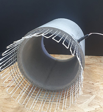
Figure 18. Smart TRC pipe concept, following [207].
Download figure:
Standard image High-resolution imageCurrent and future challenges
The smart self-sensory concept is based on taking advantage of the electrical properties and the continuous configuration of the carbon roving reinforcement. By connecting the ends of the carbon rovings to an adequate DAQ system and correlating between the measured electrical properties and the structural state, smart sensory systems are achieved. The monitoring capabilities of smart textile reinforcement are affected by the unique micro-structural mechanism of the roving within the matrix, and accordingly the measured electrical signals can reflect the structural states [199, 200, 202–204].
The concept was demonstrated for various monitoring applications and various studies were explored the potential of the carbon-based textile to be used as a multifunctional system and to yield electrical measurements that can be correlated to integrative parameters of the structural state. The electrical connections were based on direct current (DC) electrical circuits by two-probe or four probe monitoring systems [197], Wheatstone bridge configurations [199, 204], simple DC circuits [201] or by AC circuits [200, 205–207]. Although they proved the feasibility of the sensing concept for SHM purposes, several important challenges remain on the path to a useful multifunctional system. The challenges are associated with the implementation of the smart TRC elements, and with their measurement's capabilities and their interpretation. Challenges from the implementation point of view are related to the possibilities that the embedded carbon fibers will be damaged during the concrete fabrication process; to the wired connection of the smart rovings to the DAQ system and its sensitivity. Challenges from the measurement point of view are associated with the magnitude of the measured electrical signals; the sensitivity of the measurements to distinguish between the severity of structural health in full scale structural elements; the sensitivity of the electrical signals to environmental effects (temperature and moisture); the integrative nature of the signals that, currently, can yield only integrative estimation of the structural state and accordingly are limited in providing quantitative information about the location and distribution of the damaged zones. Handling these challenges are the goals of ongoing and future research and projects in this field.
Advances in science and technology to meet challenges
The challenges mentioned above can be handled by the development of improved production processes, applying advanced electrical measurement technologies, and implementing advanced analytical tools.
Issues associated with damage of the smart sensory carbon rovings, which occurred during the installation of the TRC element, can be handled by advanced manufacturing and industrial processes, since TRC structures are pre-cast in nature.
Systematic errors and inherent uncertainties as well as the sensitivity of the signals involved in the simulation of experimental tests and realistic measurements and the associate structural-electrical correlation, can be handled by the development of innovative theoretical and experimental methodologies. It should be based on advanced monitoring and electrical measurements technologies. It is particularly relevant to eliminating 'false-alarm' or 'misreading' situations in interpreting the sensory signal into SHM parameters.
Other structural phenomena (among them: the loading rate and dynamic, inertial, and dissipative effects; fatigue, creep and shrinkage of the concrete; durability of the TRC structure and its degradation along time; etc) that should be considered in the correlation between the structural response and the electrical measurement, can be handled by building a big database platform based on thorough analytical and in situ experimental investigations.
Consideration to these and other factors should be investigated in future research in the field.
Concluding remarks
The development of intelligent concrete infrastructures by using carbon-based textile reinforcement is the key to a significant and meaningful reduction in the consumption of natural materials, to a reduction of the enormous impact on the environment, and to the development of effective and safe lightweight concrete structures. Intelligent TRC structures combine high performance material and structural systems with integrated non-destructive SHM system. Recent studies demonstrated the potential and proved the feasibility of the smart textile. By advanced research, it is plausible that smart TRC will be found in various constructive elements. Enhancing their self-sensory capabilities will be a significant step to the realization of intelligent, safe, sustainable, environmentally friendly, and economic concrete structures.
Acknowledgments
This research in this field was supported by:
- The Israel Science Foundation (Grant No. 1663/21).
- The Ministry of Science & Technology of the State of Israel and Federal Ministry of Education and Research (BMBF), Germany. In the framework of Joint German-Israeli Water Technology Research Program (Grant No. 02WIL1452).
- The Israeli Ministry of Construction and Housing.
- The Umbrella Cooperation Program of the Technion and RWTH Aachen University.
- The American Technion Society within the framework of the Interdisciplinary Eco-Engineering Research Centre: Philip and Harriet Klein Contribution.
The author is grateful for the help of Eng. Barak Ofir and for the technical and administrative staff of the National Building Research Institute at the Technion.
12. Multifunctional optoelectronic composites
Donghyeon Ryu
Department of Mechanical Engineering, New Mexico Tech, 801 Leroy Place, Socorro, NM, United States of America
Status
Light has been well known as a renewable source of energy. Also, it exhibits multi-band physical characteristics that have intrigued engineering communities to use light as a sensor signal. For the past few decades, scientific advancements resulted in technological innovations in high-efficient photovoltaics and photonic/optics sensors. As SHM technologies are being matured, there has been an increasing demand on practical application of SHM by addressing two major challenges, such as dependency on external electrical energy sources and overload by big data from an increasing number of sensors. Some researchers have resorted to discoveries in material science to make technological innovations by harnessing light's unique characteristics for helping improve measurement technologies for next-generation SHM [208–213]. Optoelectronic composites showed great potential to perform as a strain sensing component as well as an energy harvester using light as an energy source [214–219]. Among the optoelectronic composites, conjugated poly(3-hexylthiophene) (P3HT) polymer is known to play a role as a multifunctional building block that exhibits a mechano-optoelectronic characteristic (i.e. optoelectronic properties varying with mechanical strain) as well as a hole and an electron dissociation spots to create an exciton (figure 19) [216]. Besides, multimodal sensing capability was encoded into the optoelectronic composites and was activated when illuminated by light in different ranges of wavelengths for different sensing modalities [217]. It was shown that the two different conjugated polymers, which respond to different wavelengths of light, were assembled to exhibit pH and strain sensing capabilities with infra-red light above 800 nm range and blue range light in 410–490 nm, respectively [217]. On the other hand, research has been conducted to use light as a sensor signal for sensing materials' response to external physical stimulus [218, 220–223]. Since late 1990's, mechanoluminescence (ML) has drawn researchers' attention to use ML for devising ML-based physical sensors as an energy efficient passive sensor, intuitive measurement of physical behavior, and a sensing method potentially suitable for vision-based SHM.

Figure 19. (a) Mechano-optoelectronic composites test specimen is subjected to cyclic tensile loading/unloading while being illuminated by broadband solar-simulated light. Direct current (DC) is generated and measured using a digital multimeter. (b) The generated DC is shown to vary with the applied tensile strain.
Download figure:
Standard image High-resolution imageThe multifunctional optoelectronic composites that use light as an energy source or as a sensor signal are considered as a promising technology as it can overcome obstacles to broaden application of SHM technologies. It can be free from dependency of external electricity and decrease the number of required sensors to downsize data volume. As more technological progresses are made toward maturing the multifunctional optoelectronic composites, it is envisioned that the novel sensor system will sense different physical phenomena using a single sensor platform and help realize carbon-neutral energy system by self-powering the sensor system as well as supplementing an energy supply system of host structures.
Current and future challenges
Major challenges have been standing in designing microstructures of the multifunctional optoelectronic composites to attain target functionalities (figure 20). The challenges are mainly attributed to lack in knowledge about how/why mutiphysics phenomena are exhibited in the optoelectronic composites. This knowledge gap consequently leads to missing constitutive equations that engineers need to have for developing the multifunctional optoelectronic composites for their own target applications through systematic design scheme. Instead, due to lack of knowledge, they tend to rely more on trial-and-error design approaches when they develop devices using the multifunctional optoelectronic composites. Advanced materials, which are mainly employed as functional building blocks for devising the multifunctional optoelectronic composites, often exhibit multiphysics properties. State variables are linked each other across different physical domains for the respective functional building blocks. For instance, microstructures of a functional building block govern the composites' functionalities, such as optoelectronic properties, as external physical stimuli deform the composites. This shows the relationship between optoelectronic properties and mechanical deformation across optoelectronic and physical domains, respectively. On the other hand, inability to design the microstructures results from lack in manufacturing methodologies suitable for forming designed microstructures. The current manufacturing process is mainly focused on building up the composites at device scale. So, it naturally overlooks how the microstructures of a functional building block are structured at micro-/nanoscales. As the different length-scale features are simultaneously affected by the single manufacturing process, design optimization for the optoelectronic composites at nano to device scale is hardly accomplished with conventional manufacturing approaches.
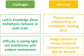
Figure 20. Challenges in broadening application of the multifunctional optoelectronic composites can be overcome through advances in science and technology.
Download figure:
Standard image High-resolution imageAlthough light is ubiquitous, use of light is not always accessible due to it is affected by environmental changes and interfered by ambient light. Therefore, on-site application of the multifunctional optoelectronic composites can hardly be realized without addressing the following challenges. Unlike electrical energy to be effectively stored in batteries or supplied through electrical wires from power source, trapping and storing light is not feasible. Relying on natural light or focused light source (e.g. laser) limits online readiness of the optoelectronic composites. More specifically, selective sourcing of different wavelengths of light is not readily available with natural sunlight due to its broadband wavelength nature. As for the composites emitting light as a sensor signal, such as ML composites, the ML signal could be interfered by ambient light in actual application that can result in corrupted sensor signal. Also, reading ML light from, for instance, spatial ML coatings could be slow although the light patterns that can be acquired from the coating are full of useful sensing information. Video recordings of ML light emission patterns require image processing to yield physical parameters to be interpreted for understanding the host structural behavior.
Advances in science and technology to meet challenges
Physics-based understanding about the functional materials in the multifunctional optoelectronic composites is essential to move away from trial-and-error design scheme to perform systematic knowledge-based design. There has been relatively less efforts made to understand how optoelectronic properties vary with various external stimuli in material science community. Conjugated polymers have been actively used for devising organic photovoltaic cells, and thus major research focus has been to maximize the power conversion efficiency [224]. Accordingly, considered are devices in ideal situations (e.g. undeformed, in mild temperature ranges, and inert environment). However, use of the optoelectronic composites for a multifunctional self-powered and multi-modal sensing and energy harvesting device needs scientific knowledgebase about multiphysics characteristics, which have been understudied in materials science community.
Understanding a relationship spanning different length scales is another challenge that hinders ones from conducting a multiscale design. Target functionalities of the optoelectronic composites are expected to be attained by forming microstructures designed in multiscale simulation tool. An exemplary solution for a molecular level simulation is large-scale atomic/molecular massively parallel simulator (LAMMPS), which is an open-source freeware developed by Sandia National Labs [225]. While it serves as a powerful tool for modeling microstructures of functional building blocks, it is challenging to theoretically study how the microstructures affect the optoelectronic composites' functionalities. Imaging tools (e.g. electron microscope, grazing incident x-ray diffractometer, and atomic force microscope) are available to visualize how microstructures are formed with different sets of manufacturing parameters. However, across the different length scales, multiscale and multiphysics modeling tool is not readily available to understand how microstructures are formed during manufacturing processes and related to functionalities of the optoelectronic composites.
The multifunctional composites can be paired with a light-sourcing material (e.g. ML) to be free from dependency on natural light source. Instead of using external light, if ML is designed to be a component of the multifunctional composites, light can be supplied on demand—when mechanical strain occurs—to activate the multifunctional composites for sensing mechanical strain [226]. Likewise, other types of luminescent materials that glow in response to external stimuli in different physical domains can be employed to be independent of the natural light source. Multifunctional composites can be created to serve as a design platform for creating composites capable of multimodal and self-powered sensing, energy conversion, and light supply. ML-based light sensor signal can be efficiently processed to yield user friendly data by using machine-learning algorithm to extract features from the abundant light information.
Concluding remarks
Unique aspects of multifunctional optoelectronic composites are attributed to the functional building blocks' unique exhibiting light sensitive characteristics and multiphysics optoelectronic and luminescent properties. Unlike conventional sensors, the composites use light as an energy source to perform as a self-powered sensing. In addition, multimodal sensing capability is enabled by selectively using different ranges of light wavelengths to distinguish different sensing modes. Discoveries in materials science enabled to invent novel multifunctional composites for harnessing light energy and using light as a sensor signal. Nevertheless, there are some challenges to overcome for broadening applications of the multifunctional optoelectronic composites as a novel measurement technology for next generation SHM. Through scientific and technological advancements, it is envisioned that the sophisticated multifunctional optoelectronic composites can be systematically designed with solid understanding about multiscale and multiphysics characteristics of the functional building blocks used for devising the composites. Also, materials characterization and multiscale simulation tools are expected to improve understanding about processing-microstructure-properties relationship of the multifunctional optoelectronic composites.
Acknowledgments
The author acknowledges NASA EPSCoR CAN (Grant #: 80NSSC17M0050), New Mexico Space Grant Consortium, and NASA's Space Grant College, and Fellowship Program for the support to advance multifunctional optoelectronic composites.
13. Robotically deployed sensors in construction
Marcus Perry
Civil & Environmental Engineering, University of Strathclyde, Glasgow, United Kingdom
Status
Sensor data underpin proactively-maintained built environments, and will support field-validation of the new low-carbon construction designs and materials needed to achieve net-zero [227]. Despite this being accepted for decades [228], the continuous monitoring and inspection of civil infrastructure remains sparse and infrequent in practice. Market failures that have promoted technology stagnation in the construction sector can and should be blamed for this, but there is also a root cause that engineers can address—today's monitoring systems are deployed by people.
Sensor technologies themselves are cheap; putting people in hazardous environments to deploy them is not. Botched monitoring campaigns cause unplanned delays to construction projects and asset utilization, costing organizations and economies millions of dollars per day. 'Who should pay these costs?' is arguably a premature question—many are unwilling to accept the uncertain return on their investments in monitoring—as data reliability depends significantly on the quality of workmanship during deployment [229]. Even trained operators make mistakes (and then promptly forget them) [230]. Without intervention, systemic human errors will continue to frustrate decision-makers, and damage industrialists' views of otherwise promising measurement technologies [231, 232].
Automation could tackle these challenges. Robots cannot (yet) match human dexterity, nor our ability to react to unforseen challenges, but they can deliver remote, repeatable and traceable sensor deployments at fixed cost.
Historically, robotic SHM has mainly focused on inspection rather than continuous monitoring, i.e. the robot retains the sensors and performs discrete measurements in time. Recent literature describes ground, wall-climbing, aerial, and underwater robots for: (i) quasi- and fully- distributed mapping of structures' local acoustic (e.g. ultrasound, ground-penetrating radar), optical (infrared, LiDAR, visual) and electrical (resistance or impedance) responses [233, 234], and; (ii) setting up mobile sensor networks to monitor environmental parameters (e.g. acceleration, temperature, radiation) using on-board electronic sensors [235]. These systems are used to assess damage indicators like vibration, corrosion, displacement, scour, or sub-/surface cracking in buildings, bridges, tunnels, and offshore assets.
There has been significantly less focus on robots to support permanent sensor installations for continuous monitoring. Noteworthy examples include the robotic installation of: embedded strain sensors in precast concrete tunnel segments [236]; 3D-printed and spray-coated self-sensing concrete repair materials for strain and crack monitoring [237], and; magnetic wireless nodes for monitoring offshore wind turbine faults via changes in distance and other environmental parameters [238].
Current and future challenges
Some of the future research challenges facing robotic sensor deployment are not unique to the field [235, 239], and include the development of: (i) resilient and manoeuvrable robots for hazardous and complex environments; (ii) robust long-term robotic navigation systems; (iii) optimal sensor placement and inspection strategies in time and space; (iv) handling big data and energy budgets; (v) data fusion from multiple sensor modalities; and (vi) conducting extensive ground-truthed field testing.
More unique challenges stem from the field's need to integrate robots, sensors, data analytics and manufacturing, and including the development of: (vii) inspection systems, sensors, smart materials and tooling which are compatible with (and ideally take full advantage of) robotic sensor deployment; (viii) fully-automated real-time decision making based on perceived structural health; (ix) robotically-deployed active sensing (where fixed sensors are excited by robots to measure local responses); (x) robotic sensing for off-site construction manufacturing, and; (xi) underwater construction sensing (enough of a distinct challenge to warrant its own point!).
Finally, while they are not technical challenges: (xii) we should adopt consistent terminology, as it will allow for more rapid identification of gaps in knowledge; authors should make clear distinctions between inspection and continuous monitoring systems, and whether robots are being used to deploy a temporary (i.e. delivered) or a permanent (i.e. installed) monitoring solution; and (xiii) research should be done to quantify the costs and benefits of using robotics (relative to using people) in different construction sectors and nations, as this will allow engineers to focus efforts on developing robotic deployment strategies which have maximum impact.
Advances in science and technology to meet challenges
Advances in soft robots may help us meet some of these challenges. Soft robots are good at manoeuvring in tight areas and can keep their control electronics remote when the environment is radioactive [240]. The soft robot itself can even act as a mobile sensor deployed by another robot [241].
Tooling for grasping and manipulation require ongoing research to even begin approaching human dexterity, and further research into artificial intelligence will be required for robotics to match our ability to react to new events through pattern recognition. If developed further, tactile skins [242] will allow robots to apply pressure with high accuracy and precision; this will be useful for remote contact-based inspection (e.g. acoustic and electrical tomography), sensor installation, and active sensing.
Advances in the 3D printing of functionalized electrically-conductive materials [243] can be adapted to robotic systems for on-site or in-factory deployment. Indeed, any advances in additive, hybrid and digital manufacturing research should be considered for robotic sensor installation.
Developments in machine learning, such as convolutional and transformer neural networks [244], will support autonomous analysis and decision-making both for robots and for SHM. Exploration of how this dense information can be optimally combined and leveraged will require further integration of robotic sensing platforms and artificial intelligence with building information modeling [245]. Even alone, machine learning algorithms for SHM could be deployed directly on swarm robots as edge computing advances [246]. This reduces wireless communication demand, conserving battery power.
Concluding remarks
The last decade has seen rapid developments in robotic inspection for construction, and its supporting research areas. We should now complement this with robotically-installed continuous monitoring systems for key SHM indicators like strain. We will need to work more collaboratively than ever before to integrate systems within this domain. Researchers who develop measurement and repair technologies should consider integration with robotics early on; it could be the key to de-risking deployment. There are opportunities for data analysts to explore the change to the cost/value of information that stems from robotic sensing and its interplay with both human decision support systems and fully autonomous robotic decision-making. Robotics developers should support wider access to their platforms, so that other developers can design well-integrated systems; these could further enhance simultaneous localization and mapping using local construction fault features.
Finally, companies and governments should support the work with access to funding and field sites. Robotic sensing shows significant promise in breaking construction stalemates to unlock ubiquitous infrastructure monitoring, and with it a slew of financial, economic, and environmental benefits.
14. Robotics-based remote sensing and monitoring
Rebecca Napolitano1 and Fernando Moreu2
1 The Pennsylvania State University, State College, PA, United States of America
2 University of New Mexico, Albuquerque, NM, United States of America
Status
Remote sensing detects and monitors the physical properties of an area by measuring reflected and emitted radiation away from a region of interest. While there are various methods of remote sensing, robotics-based remote sensing facilitates human interaction beyond the realm of visual data and enables physical properties of a structure to be queried.
Unmanned aerial vehicles (UAVs) have gained traction for SHM applications over the last decade (figure 21). As the area of sensors and cameras is advancing, many unique platforms can be developed for UAV integrated instruments; which provide high spatial resolution data integrate directly with different sensors such as RGB cameras or LiDAR. Looking forward, the prospects of remote sensing data analysis will continue to improve as machine learning, artificial intelligence, and computer vision techniques enhance the facilitate live UAV data analysis (figure 22) [248–251].
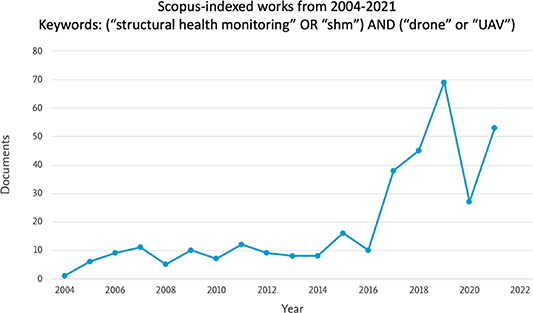
Figure 21. Number of publications per year indexed in the Scopus scholarly database. Keywords included the following search conditions (1) 'structural health monitoring' or 'SHM' and (2) 'drone' or 'UAV' [247].
Download figure:
Standard image High-resolution image
Figure 22. Robotics-based monitoring examples: (left) new aerial system of intelligent measurement integration (NASIMI) [248, 249]; (right) rock-slide detection using machine learning with BRUTUS [250, 251].
Download figure:
Standard image High-resolution imagePresently in SHM, there are many studies investigating different light-weight sensors on UAV. For example, researchers have used RGB cameras on UAVs to collect 3D data automatically. Morgenthal and Hallermann discussed the flight properties of UAVs and the resulting influencing factors on the image quality [252]. Roca et al utilized a combination of a lightweight laser scanner and a UAV for generating 3D point clouds for building assessment [253]. As stated above, the systems typically consist of one UAV with a special sensor which covers a specific application. As camera technology is continuously evolving, image quality and resolution will continue to improve for SHM applications.
Controlling the flight path of the UAV can be done using remote control. However, applying automated path planning will lead to an automatically calculated optimal flight path. Path planning of UAVs should consider obstacle avoidance, maximum coverage, sensor limitations, vehicle motions, and time and cost-efficiency. Some methods such as wavefront algorithm [254], spanning tree algorithm [255], and neural network [256] are used to compute the flying path in a simplified grid space. Other methods, such as traveling salesman problem, focus on finding the shortest path passing through pre-defined viewpoints [257, 258].
Considering continued advancements in other aspects of UAV hardware, multi-rotor UAVs offer great promise for SHM as they can maintain a stable position without much movement or vibration even in windy conditions [259]. Additionally, recent advances in visual navigation systems have allowed UAVs to hover in place without the need of a strong GPS signal by using optical, infrared, and/or ultrasonic sensors [260, 261].
Considering the accuracy and sensitivity of this as a SHM tool, UAVs were used to detect displacement in a large retaining wall with high accuracy using photogrammetric methods and computer vision algorithms in the aforementioned study by Hallermann and Morgenthal [252]. Validation was done by intentionally removing some bricks and replacing them with thinner plates to simulate movement, and the UAV images were able to accurately detect displacement. In another study by Polydorou et al [262], digital cameras on UAVs were used to measure deflection of a bridge with high accuracy compared to traditional displacement gauge sensors. However, it was found that the accuracy of UAV-based deflection measurements are dependent on the accuracy of the UAV movement. Garg et al [249, 263], Nasimi and Moreu [248, 264] and Nasimi et al [265] studied the effect of UAV movement in the accuracy of displacement measurements both indoor and outdoor in the context of bridges SHM and railroad bridge management. For additional commentary on the accuracy and sensitivity of UAVs for civil SHM, the reader is suggested to view Sreenath et al [266]. Overall, UAVs show potential for accurately monitoring the structural health of bridges, but careful consideration must be given to the accuracy and sensitivity of the sensors used and the movement of the UAV itself.
Current and future challenges
Although the UAVs have notably improved over the last decade, there are two different types of challenges impeding research in robotics-based remote sensing for SHM; these include (1) policy-centered challenges and (2) hardware and software integration challenges.
In the US, the Federal Aviation Administration regulates UAVs via the Code of Federal Regulations Part 107. One of the main policy-centered issues faced by UAV SHM researchers is the Part 107.31 rule which specifies that the pilot and an observer must be able to see the UAV throughout the entire flight [267]. While this could be feasible in some scenarios, there are many where it would not be; during post-disaster reconnaissance, it may be unsafe for researchers to enter a building to keep a line of sight. Additional policy-centered challenges are emerging as more research considers multi-drone SHM teams [268, 269]. Part 107.35 prohibits a person from acting as the flight controller, remote pilot, or visual observer in the operation of more than one UAV at a time [270]. Thus if a researcher wanted to examine how a swarm of five drones could inspect a structure, they would need ten people. Furthermore, rules of engagement between an autonomous agent and a remote pilot are not clarified. Thus, current policy impedes real-world testing and research of fully autonomous UAV-based SHM.
Hardware and software integration challenges span from battery life to behavior in inclement weather and remote areas. Battery life plays a vital role in cases when a longer time of flight is needed but it is also key to enable the integration of new sensors in the robots being used. Increased capacity for a more powerful battery currently stands in opposition to the increased weight of the system which can further reduce the time of flight for a device. Furthermore, manufacturing cost could increase, which affects the system's performance. An additional physical challenge when using UAV for SHM is that they are susceptible to weather conditions and they cannot maneuver appropriately in unfavorable climatic circumstances. Windy weather not only deviates a UAV's path, but also it contributes vibration which directly impacts the quality of data. Furthermore, in many places, it is hard to have wireless communication. As a UAV needs reliable network connectivity to be able to transmit data and location between pilot and UAV, this jeopardizes the robustness of data collection in more remote areas.
While the results of previous practical studies realized with the UAV system indicate the potential of UAV-based inspection, there are other software-centered limitations. The accuracy of the rough point cloud data based depends directly on the accuracy of the determined UAV pose. A second aspect is to evaluate the improvement of image quality by using a spotlight. That is an essential fact to guarantee a complete inspection also of poorly lit bridge areas. Finally, the usability of appropriate indices and orthophoto mosaic for bridge inspection needs more effort to investigate.
Advances in science and technology to meet challenges
For many policy-centered challenges to be surmounted, experimental testing, best practices development, and validation studies must be carried out by the SHM community. With regard to the line-of-sight challenge, one organization has been able to successfully gain a waiver under certain circumstances [271]. The argument for this exception required documentation of the need and experimental verification of performance under the given circumstances. The SHM community will need to perform similar studies if we aim to move towards using UAV to monitor structures preventatively rather than reactively. Similarly, experimental testing and validation using multi-UAV teams needs to be carried out for SHM applications to examine and demonstrate the safety capacity of swarm algorithms. Regarding the current lack of procedure when two autonomous systems interact, regulations for September 2023 will require all UAV to comply with new Remote ID requirements; any UAV that are not compliant, will not be able to be used. This change in policy could help SHM researchers build the case for allowing autonomous SHM sensing and monitoring. This policy would force all UAVs to be able to communicate consistently with each other; this would facilitate predicated rules of engagement for when two different robots, where either one or both are autonomous, meet.
To rise above many of the existing challenges previously presented, the following areas are suggested for development and research in the next decade:
- Development of new hardware-software integration for high-rate DAQ, including data fusion, event-based computer vision sensing, and low-cost sensor integration that enables a faster rate of discovery and integration.
- Increase exploration on human-robotics interfaces with new data visualization, Augmented Reality, pilot-inspector-engineer hands-free control of robotics.
- New outdoor testing environments that enable testing outside the implementation of robotics, sensors, and inspections with human in the loop validation, including monitoring of UAV trajectory and algorithms outdoors, large scale validation, and below water robotic inspection of structures and environments.
Concluding remarks
As, the price and size of a complete system have reduced considerably, this technology has become more accessible for government and research institutions for SHM applications. As UAVs continue to become more user-friendly and affordable, their ubiquity will catalyze further opportunities for novel SHM data analysis workflows. There are many additional challenges on the horizon and it is clear that science and policy will need to work together. Some of those challenges include cybersecurity concerns in SHM in the context of smart cities, human-in-the-loop decisions, national and global security, and public-private involvement in policy development that drives new laws and regulations. Finally, there are educational opportunities in K-12 and College to assist to train the future worker with the required skills to work on addressing these challenges and leading new areas still to be identified.
Acknowledgments
The authors thanks Rakeh Saleem And Mahsa Sanei for their input and contributions in this document as well as Steve Colligan for fruitful discussions.
Funding sources
This work was funded by TRB Safety IDEA Project 32: Railroad Bridge Inspection for Maintenance and Replacement Prioritization Using UASs with Laser Scanning Capabilities, Project 160416-0399 and TRB Safety IDEA Project 37: Measuring Behavior of Railroad Bridges under Revenue Traffic using Lasers and UAVs for Safer Operations: Implementation, Project 163 418-0399, Part of this work was partially supported by the Collaboration Grants from the New Mexico Consortium: Nos. 249-01 NO. Q02151 and A21-0053. The financial support of this research is provided in part by the Air Force Research Laboratory (AFRL, Grant Number FA9453-18-2-0022), the Transportation Consortium of South-Central States (Tran-SET), Project Number: 20GTUNM31, and the Office of Naval Research Award Number N00014-21-1-2169.
This material is based upon work supported by the National Science Foundation under Grant Nos. BCS 2121 909 and IIS 2123 343. Any opinions, findings, and conclusions or recommendations expressed in this material are those of the author(s) and do not necessarily reflect the views of the National Science Foundation.
15. Multi-temporal interferometric synthetic aperture radar (SAR) for buildings and infrastructure monitoring
Giorgia Giardina1 and Pietro Milillo2,3
1 Department of Geoscience and Engineering, Delft University of Technology, Delft, The Netherlands
2 Department of Civil and Environmental Engineering, University of Houston, Houston, TX, United States of America
3 Microwaves and Radar Institute, German Aerospace Center (DLR), Oberpfaffenhofen, Germany
Status
Recent developments in satellite monitoring technology have shown enormous potential in detecting buildings and infrastructure deformations, which are often connected to early signs of structural distress. The possibility to measure displacements remotely, with high level of accuracy and frequent updates, can overcome some of the limitation of in-situ inspections, which are typically labor-extensive, time consuming and only performed every few years. Satellite-based monitoring can therefore effectively complement traditional methods for structural condition assessment.
SAR satellites senses the Earth's surface by emitting electromagnetic waves and analyzing the target backscattered signal (figure 23). The phase of the signal contains information about the distance between the sensor and the target [272]. Multi-temporal interferometric SAR (MT-InSAR) techniques exploit multiple images (generally >20) for mitigating noise effects due to the atmosphere to estimate the target relative displacement between multiple acquisitions in time [273].
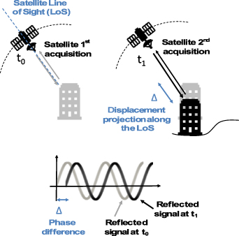
Figure 23. Schematic representation of InSAR acquisition geometry and target displacement estimation.
Download figure:
Standard image High-resolution imageThe use of microwave band enables day-and-night and weather-independent measurements, which are updated with weekly frequency. With the launch of more satellites into the same orbit, MT-InSAR deformation measurements can now reach millimeter accuracy in urban areas [274]. These features, combined with dense and large spatial coverage, and the possibility to access archived images for retrospective analysis of unmonitored structures, have driven in the past decade a rapidly increasing use of InSAR data for civil engineering applications.
MT-InSAR techniques allow the extraction of displacement time-series for targets that show stable reflective properties in time. Thanks to their physical nature, buildings and civil infrastructure can provide a high number of these targets, making MT-InSAR monitoring particularly effective in urban areas (figure 24). In the past decades, extensive literature has focused on proving the reliability of MT-InSAR to accurately measures deformations of different types of structures. Most of these studies have concentrated on cross validation of satellite-based monitoring through comparison with independent ground-based measurements for real case studies. Examples included buildings [275, 276], railways [277], roadways [278, 279], dams [280] and bridges [281, 282]. An extensive literature review on MT-InSAR civil engineering application can be found in [279].

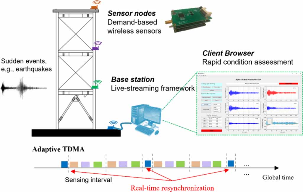
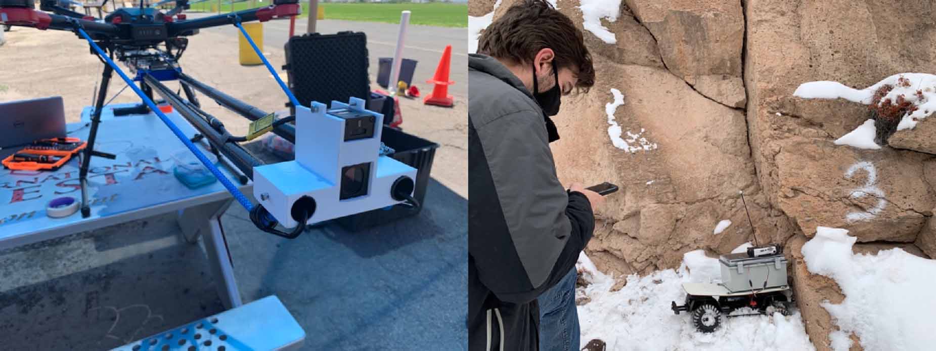
Figure 24. InSAR cumulative displacements (top) highlighting the subsidence induced by the Crossrail tunnel excavation in London (bottom left). Data from April 2011 to December 2011. Negative values indicate movements away from the satellite. At building level (bottom right), the satellite-based displacements can identify the profile of the building differential settlements.
Download figure:
Standard image High-resolution image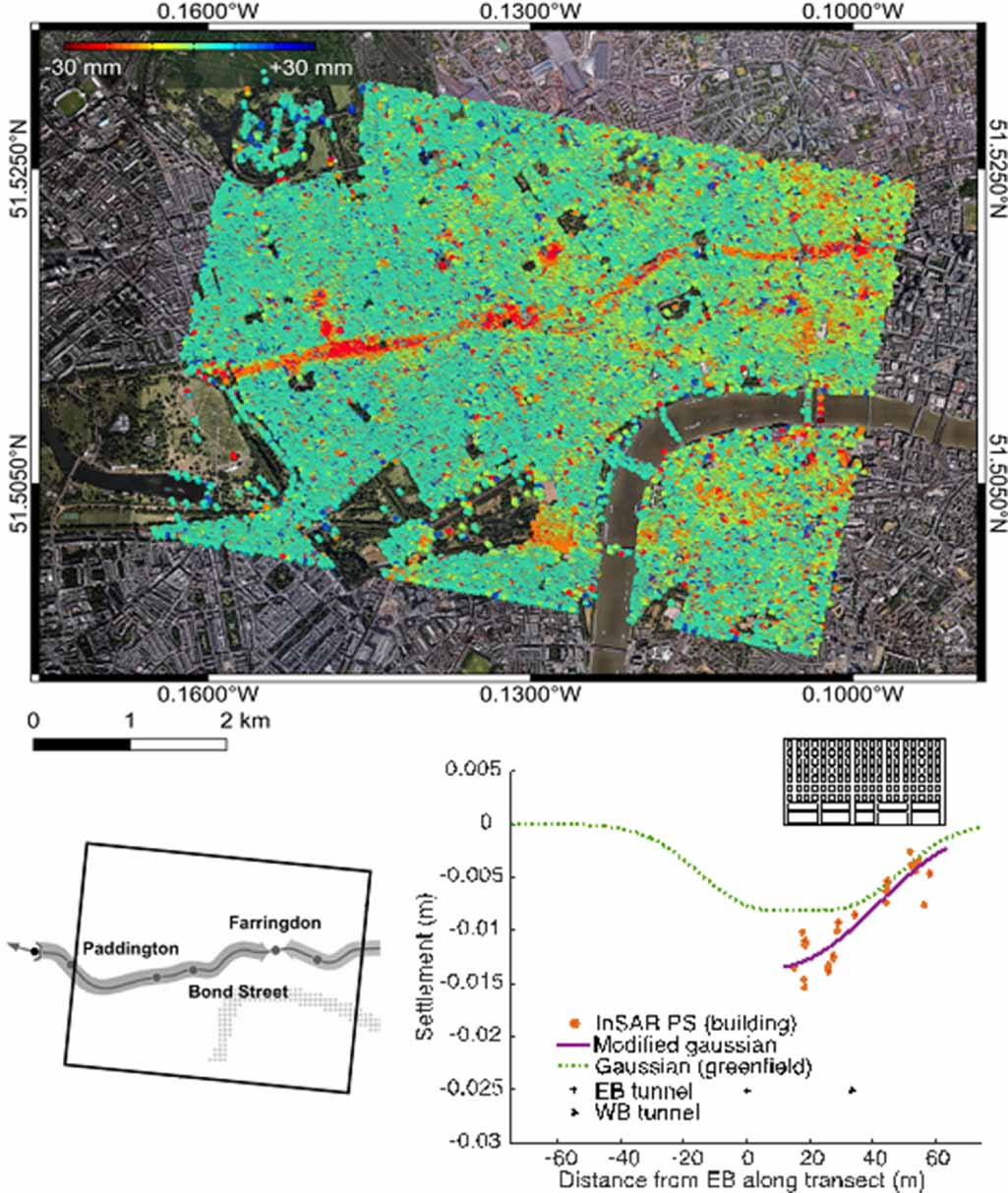
Based on these promising results and the rapid development of the field, MT-InSAR approaches have the potential to move from retrospective analyses to early detection of anomalies and decision-making support for infrastructure maintenance prioritization.
Current and future challenges
InSAR data have been proven effective in monitoring urban areas and infrastructure, both at asset level [281, 282] and at network scale [279]. However, there are still challenges to overcome for a full integration of satellite-based monitoring within regular inspections and assessment activities. These challenges depend on inherent features of both sensors and data processing, which are substantially different from most monitoring systems commonly applied to civil engineering structures.
First, InSAR data have specific geometrical limitations. While for traditional monitoring systems the direction of measured displacements is pre-defined or known, InSAR can only measure the displacement component along the satellite Line of Sight (figure 23). Furthermore, the near-polar orbit of SAR satellite makes them less sensitive to north-south displacements, even when the availability of data from different orbit trajectories enable to estimate the projected vertical and horizontal displacements.
Second, the number of available monitored points is not uniformly distributed all over the Earth's surface, and their location is not known a-priori. The density of points depends on satellite coverage and quality of the reflected signal. This could be limiting for rural areas, which are typically characterized by a lower density of monitored points, and small infrastructure, like short bridges, for which the number of points might not be sufficient to interpret structural deformations.
Third, while the wide-area coverage of SAR satellites enables the analysis of displacement phenomena at regional scale, the accurate transformation of signal phase information into displacement measures requires some preliminary knowledge of the type of deformation being observed, e.g. slowly vs rapidly progressing, or spatially localized vs distributed over a large area. Wrong assumptions on the linearity of the deformation process could for example lead to underestimate movements which are characterized by highly nonlinear behavior. Additionally, the maximum deformation rate that can be estimated by InSAR techniques is limited by the signal wavelength, satellite revisit time and specific processing techniques.
Finally, the current and future satellite constellations specifically dedicated to surface displacement measurements is creating increasingly large volumes of data. The full exploitation of these data will require new storage, processing, and interpreting strategies. A more in-depth discussion of current challenges and promising solutions for InSAR infrastructure monitoring is presented in [283].
Advances in science and technology to meet challenges
InSAR geometry related limitations, such as the assumptions made for projecting InSAR LoS displacements in 3D, can be improved using InSAR data from multiple orbits and different sensors. The processing of data acquired from different incidence angles, ascending and descending orbits and left/right looking view can facilitate decomposition in vertical and east-west displacement projection [284]. This possibility will be maximized by the new SAR missions which are planned to be launched in the coming years [285], leading to the acquisition of different set of measurements for the same areas.
To increase the availability of monitored targets, techniques are being developed to exploit the target reflectivity even on limited time intervals, e.g. [286]. Such improvements can help in situations of poor signal reflectivity, induced for examples by snow, flooding or structural rapid changes. Furthermore, the availability of targets on specific and pre-defined locations can be guaranteed through the installation of corner reflectors which can provide a stable signal. Additionally, the use of virtual simulators [287] can help predicting the density and likely location of targets over a certain area of interest prior to the actual data processing.
Shorter time intervals between subsequent DAQs are required to improve the performance of current nonlinear approaches, which are more likely to capture rapidly changing displacements [273]. Also in this case, the shorter revisit times expected from future SAR satellite constellations have the potential to expand SHM applications. Integration with independent ground-based measurements [288] and SAR techniques exploiting the signal amplitude [289] can also support the validation of modeling assumptions.
Machine learning techniques can be used to process and interpret the growing volume of InSAR available data. Examples are the application of neural network approaches to the analysis of displacement measurements on large scale [290] and the automated detection of anomalous points in displacement time series [291]. Overall, the effective use of MT-InSAR measurements to support buildings and infrastructure condition assessment depends on a clear understanding of the effect of assumptions and input parameters on the data processing and of the structural response connected to the monitored deformations. This ultimately calls for a stronger cooperation among remote sensing experts, data scientists and civil engineers.
Concluding remarks
Radar interferometry can provide high-resolution, frequent and spatially dense measurements of structural deformations, complementing in situ conventional monitoring and offering an unmatched solution for regional scale and long-term monitoring. Current limits to a systematic use of InSAR measurements for SHM of buildings and infrastructure are related to (a) the challenge of decomposing the one-dimensional displacement projection as it measured by the satellite along its LoS, into the actual three-dimensional displacement components which are needed to interpret structural deformations, (b) the availability, location and distribution of monitored points for each single structure, (c) the dependence of measurement accuracy on modeling assumptions, signal wavelengths and other satellite and processing algorithm features, and (d) the challenge of storing, processing and interpreting the increasingly large amount of acquired data.
The current and coming availability of SAR satellites specifically dedicated to surface deformation detection, as well as the rapid advance of MT-InSAR algorithms, are expecting to play a key role in addressing these challenges. Such developments could rapidly lead into a future routinary use of InSAR data to support early warning systems and maintenance planning tools.
Acknowledgments
This publication is part of the Vidi project InStruct, Project Number 18 912, financed by the Dutch Research Council (NWO).