
ABSTRACT
We describe a new type of coronagraph, based on the principle of a phase mask as proposed by Roddier and Roddier a few years ago but using an original mask design found by one of us (D. R.), a four‐quadrant binary phase mask (0, π) covering the full field of view at the focal plane. The mutually destructive interferences of the coherent light from the main source produce a very efficient nulling. The computed rejection rate of this coronagraph appears to be very high since, when perfectly aligned and phase‐error free, it could in principle reduce the total amount of light from the bright source by a factor of 108, corresponding to a gain of 20 mag in brightness at the location of the first Airy ring, relative to the Airy peak. In the real world the gain is of course reduced by a strong factor, but nulling is still performing quite well, provided that the perturbation of the phase, for instance, due to the Earth's atmosphere, is efficiently corrected by adaptive optics. We show from simulations that a detection at a contrast of 10 mag between a star and a faint companion is achievable in excellent conditions, while 8 mag appears routinely feasible. This coronagraph appears less sensitive to atmospheric turbulence and has a larger dynamic range than other recently proposed nulling techniques: the phase‐mask coronagraph (by Roddier and Roddier) or the Achromatic Interfero‐Coronagraph (by Gay and Rabbia). We present the principle of the four‐quadrant coronagraph and results of a first series of simulations. We compare those results with theoretical performances of other devices. We briefly analyze the different limitations in space or ground‐based observations, as well as the issue of manufacturing the device. We also discuss several ways to improve the detection of a faint companion around a bright object. We conclude that, with respect to previous techniques, an instrument equipped with this coronagraph should have better performance and even enable the imaging of extrasolar giant planets at a young stage, when coupled with additional cleaning techniques.
Export citation and abstract BibTeX RIS
1. INTRODUCTION
The detection of faint extended or pointlike sources near bright astrophysical objects requires both a high angular resolution and a high dynamical range achievable with a dedicated instrument—a coronagraph—that can suppress most of the light from the bright source. Several designs have been proposed, but in all cases the effect of the atmospheric turbulence is a strong limitation, even with an excellent adaptive optics (AO) system, which appears mandatory in all cases.
A coronagraph with high dynamic range could be a powerful tool in a variety of astrophysical topics. In stellar physics, one could detect companions like low‐mass stars, white or brown dwarfs, and also dust shells around asymptotic giant branch (AGB) and post‐AGB stars, protoplanetary disks, or even the extended counterpart of the accretion disk of young stellar systems. In the field of extragalactic astrophysics, this technique can greatly contribute to an understanding of the structure (torus, disk, jets, star‐forming regions, etc.) and dynamical process in the environment of active galaxy nuclei (Seyfert I and QSOs). The last example is related to the problem of the direct imaging of extrasolar planets, a question which is now becoming of paramount importance; a coronagraphic device appears absolutely mandatory since the contrast between the star and an orbiting planet, even as bright as Jupiter, is 109 in the visible and the near‐IR. The space programs that currently envisage such a detection (DARWIN/EED on the European side: Léger et al. 1996; and Terrestrial Planet Finder on the U.S. side: Angel & Woolf 1997) are based on the interferometric coronagraph imagined by Bracewell (1978), where the light from several distant telescopes is combined with a π phase shift applied on half of the beams. Here, we are concerned only with single‐aperture telescopes, the angular resolution of which is suited for the detection of outer planets orbiting nearby stars (10 pc typically). Different solutions for improving the coronagraphic capability have been proposed.
The first coronagraph was introduced by Lyot (1939) to observe solar protuberances and corona: it used an opaque amplitude mask at the focus, combined with a so‐called Lyot stop at the relayed pupil. In the past few years, new concepts of stellar coronagraphs were described, using a modification of the phase rather than of the amplitude. Gay & Rabbia (1996; see also Baudoz, Rabbia, & Gay 2000) have proposed the concept of an interferometric nulling coronagraph (the Achromatic Interfero‐Coronagraph [AIC]). This system is a modified Michelson's interferometer exploiting pupil rotation and therefore avoiding the use of a physical mask. The beam goes through a focus in one of the arm and then provides an achromatic π phase shift. Note that the AIC gives a perfect achromatic nulling when the source is exactly on‐axis. Roddier & Roddier (1997) have proposed another type of stellar coronagraph using a disk phase mask (DPMC), the size of which is typically half the diameter of the Airy peak. The π phase shift introduced by the mask, produces a self‐cancellation of the stellar light by destructive interferences inside the geometric pupil area.
The phase‐mask technique is more efficient than the Lyot mask for observing faint objects very close to the star, but it exhibits a strong wavelength dependence (the mask diameter varies as λ) and is sensitive to tip/tilt errors. For optimal performance, the spectral bandwidth must be restricted to 20 nm (for a wavelength of 1 μm). In addition, pointing accuracy is very critical since 20 mas residual tip/tilt provides an extinction of no more than 2 mag (Guyon et al. 1999).
In our new concept, we propose to start from this idea of dividing the Airy pattern in several parts and applying a π phase shift to half of them, so that a destructive interference is produced. The idea is that splitting is done according to a four‐quadrant design. As we show, this results in a more efficient nulling and a lower sensitivity to atmospheric seeing. The achievable spectral bandwidth is larger than with the DPMC because the mask dimension does not depend on the wavelength.
In §§ 2 and 3, the principle of the four‐quadrant coronagraph is depicted, and first results of simulations are presented for both the ideal phase‐error–free case and the real world. In § 4 we discuss briefly the questions of manufacturing the mask, its limitations, and the improvements that can be achieved through data processing. In § 5 we examine the actual performance that can be expected, especially considering the question of direct imaging of exoplanets. In a following paper, a complete simulation of the different physical parameters, spectral bandwidth, turbulence level, tip/tilt accuracy, size of the Lyot stop, and so on, will be addressed.
2. PRINCIPLE AND SIMULATION OF THE "PERFECT CASE"
Figure 1 presents a layout of the system we propose. As in the coronagraph invented by Roddier & Roddier (1997), this setup uses a transmittive phase mask in the focal plane to provide a π phase shift on a well‐defined area. Instead of a disk, here the mask is arranged according to a four‐quadrant pattern: two quadrants on one diagonal without phase shift and the two other quadrants providing a π phase shift (Fig. 2a). A first lens makes an image of the pupil where a Lyot stop is installed, and finally a second lens provides the image of the focal plane. The mask extends all across the field of view, but in practice one uses a finite‐size mask (see § 3).
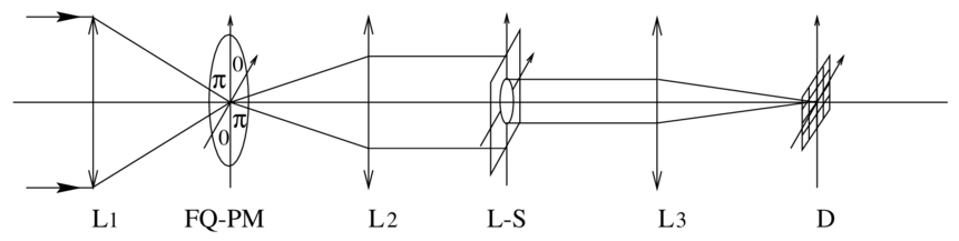
Fig. 1.— Optical scheme of our new phase‐mask coronagraph: L1, L2, and L3 are three lenses in the optical system. L1 provides a large F/D ratio on the four‐quadrant phase mask (FQ‐PM), L2 images the pupil in the second plane, the Lyot stop (L‐S) suppresses the diffracted starlight, and finally L3 forms the coronagraphic image on the detector (D).
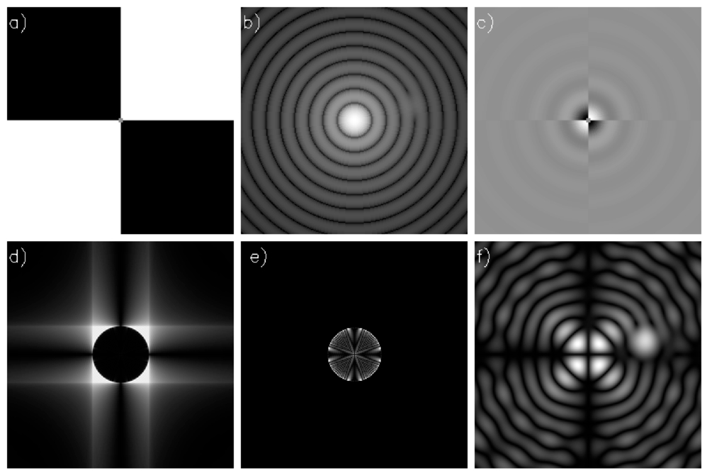
Fig. 2.— Numerical simulation illustrating the principle of the four‐quadrant coronagraph. A companion 15 mag fainter (flux ratio of 106) is located 2.1λ/D away from the star. The individual images show (a) the shape of the phase mask (white for 0 phase shift, black for π phase shift), (b) the Airy pattern displayed in intensity, (c) the complex amplitude of the star phase shifted by the mask, (d) the exit pupil, (e) the exit pupil through the Lyot stop (95% of the pupil diameter), and (f) the coronagraphic image where the companion is clearly visible. Images are displayed with nonlinear scale.
Using such a device, and provided that the image of the bright star is exactly located at the center of the mask, the four beams combine in a destructive way at infinity and the stellar light is mostly rejected outside of the pupil area, with a stronger contribution near the edges (Fig. 2d). Then a Lyot stop, performing a spatial filtering, is placed in this exit pupil to remove the diffracted starlight. The basic optical design is presented in Figure 1, and the different steps of image formation are given in Figure 2. Although corresponding to an ideal case, this simulation clearly shows the detection of a close companion 15 mag fainter than the star. The four‐quadrant symmetry provides a perfect balancing of fluxes between each pair of quadrants, as long as the star is accurately centered.
We have performed numerical simulations of the four‐quadrant phase‐mask coronagraph (FQ‐PM) using IDL software. Large arrays were used (up 1024 × 1024), so as to minimize the aliasing effect of fast Fourier transform and, second, to achieve a large pixel sampling of both the pupil and image plane. Only the inner part of the Airy pattern is taken into account (up to 15λ/D). The phase‐mask shape fits the radial symmetry of the Airy pattern.
The intrinsic nulling performance of the four‐quadrant coronagraph is theoretically excellent and comparable to the AIC (Baudoz 1999), in the monochromatic case: the rejection factor is more than 108 in intensity, as illustrated in Figure 3, where the monochromatic radial profile of a stellar image given by a telescope is shown in the standard case and in the case where an FQ‐PM is used. Compared to the AIC, an advantage is the lack of image flip that could produce an uncertainty on the detection of a companion. However, it must be clear that the finite‐wavelength bandwidth, the residual optical aberrations, and especially the atmospheric turbulence become important limitations, as in any of the recently proposed solutions. The expected range of attenuation is shown in Figure 3 for several azimuth angles between 1° and 45°. The intensity dispersion in the coronagraphic profile is approximated by an azimuthally averaged profile in the next plots. A cancellation of about 20 mag is achievable relative to the maximum intensity of the star. However, a faint companion lying exactly along an axis of the mask is attenuated by about 2.15 mag owing to the π phase shift between two quadrants. This attenuation decreases to 0.64 mag when the companion is located at 0.5λ/D of one of the axes. Actually, the attenuation provided by only two quadrants is not significant compared to that of a four‐quadrant phase mask. The photometry of a companion is therefore little affected this way. Moreover, to avoid this effect when looking for faint companions, a second measurement can be performed after rotating the field by 45°.
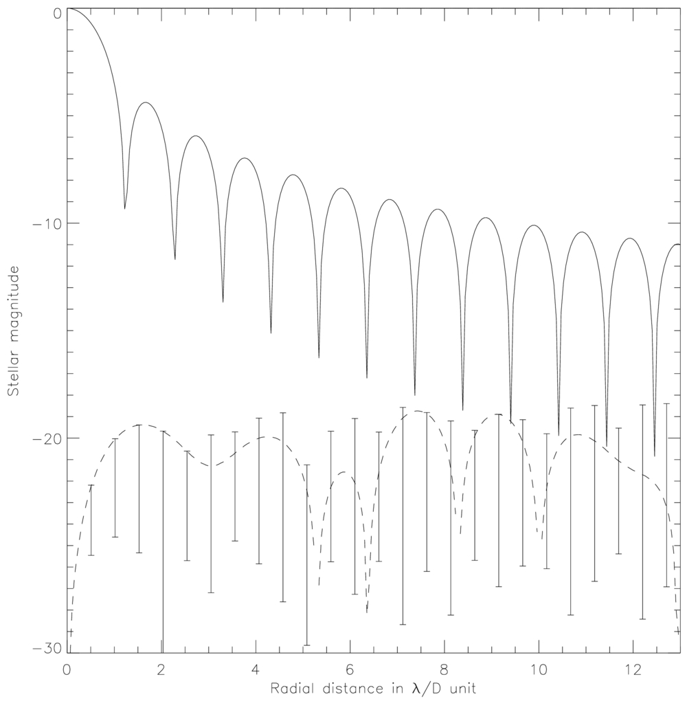
Fig. 3.— Theoretical radial profiles obtained with a FQ‐PM as a function of the azimuth angle. The solid line shows the Airy pattern radial profile. The dashed line is the coronagraphic profile obtained at 45° relative to the x‐axis. The error bars indicate the range of intensity for azimuth angle between 1° and 45°.
Figure 4 gives a comparison of the FQ‐PM with a DPMC in a perfect atmosphere‐free and aberration‐free system. The theoretical gain on the DPMC is typically 13 mag at the location of the first Airy dark ring, if everything else is otherwise perfect. However, the performance of the DPMC can be largely improved using pupil apodization technique as shown by Guyon & Roddier (1999). This point will be discussed in the following paper.
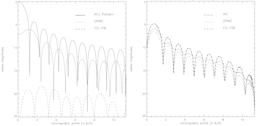
Fig. 4.— Coronagraphic azimuthally averaged intensity profiles for the DPMC (dotted line), the FQ‐PM (dashed line), and the AIC (dash‐dotted line on the right plot). The solid line gives the Airy pattern radial profile as a reference. The left plot is given for a perfect case in monochromatic light and phase‐error–free system. The Lyot stop diameter is 95% of the pupil size. On the right plot intensity profiles are given for a residual atmospheric tip/tilt of 0.088λ/D rms (8.4 mas on a 3.6 m telescope at 1.65 μm), for each coronagraphic device.
3. PERFORMANCE ESTIMATION FOR A REAL SYSTEM, COMPARISON WITH OTHER SYSTEMS
In this section, we are interested in the nulling performance of the FQ‐PM in the real life where tip/tilt of the wave front is no longer perfectly zero.
Figure 4 shows a comparison of the FQ‐PM nulling performance with and without a residual atmospheric tip/tilt of about 10 mas, which must be considered as a small one in ground‐based astronomy. As soon as a residual tip/tilt occurs, even a fairly small one, the nulling performance is strongly degraded. In our example, the tip/tilt of 0.088 λ/D, i.e., 8.4 mas on a 3.6 m telescope at 1.65 μm, leads to a degradation of typically 12 mag. The residual tip/tilt gives clearly the major contribution in the loss of nulling.
The performance of the FQ‐PM is also compared to the AIC and the DPMC regarding the effect of tip/tilt errors. It is interesting to notice that the DPMC only exhibits a significant loss of contrast while the FQ‐PM and the AIC profiles undergo similar degradation of nulling performance. Nevertheless, the FQ‐PM provides the best theoretical performance with an attenuation of about 10 mag at an angular separation of 2λ/D. Numerical simulations show that the effect of a uniform tip/tilt provides a symmetrical residual intensity in the focal plane. In fact, this is true for any kind of coronagraph. The coronagraphic radial profile is therefore identical for all azimuth angles.
The sensitivity of the nulling performance to residual tip/tilt of the adaptive optics actually depends on the location in the image. We investigated this effect by measuring on the coronagraphic image the residual energy in the central peak, in the halo, and in the whole Airy pattern, and by renormalizing with the same quantities as measured in the perfect case (without any pointing error). We obtain the degradation factors as shown in Figure 5. We conclude that the degradation is much larger in the peak than in the halo, a favorable case when one aims at detecting a companion at a few λ/D. The results are clearly fitted by a square power law, as shown on Figure 5, where the χ2 factors are indicated. This square law is expected, as a Fresnel's diagram shows: the amplitude (square root of the intensity) of the resulting electric field vector is proportional to the departure of the phase from its nominal value (0 or π), this departure being proportional to the amplitude of the residual tip/tilt.
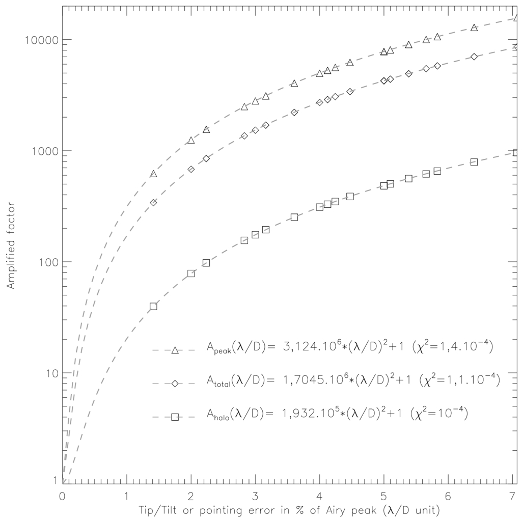
Fig. 5.— Degradation of the coronagraphic performance vs. angular offset from the center. The degradation factor is the residual energy normalized to the perfect case, as measured in the entire Airy pattern (diamonds), in the Airy rings (squares), and in the Airy peak (triangles). The offset is performed along a diagonal of the mask, and thus corresponds to a maximum degradation. The simulation is performed with a Lyot stop of 95% of the pupil diameter.
We have simulated a more realistic case than a pure tip/tilt by introducing in the model a corrugated wave front representative of the one found after correction by an AO system on a ground‐based telescope. This is illustrated on Figures 6 and 7, where a very favorable situation and a more realistic one have been studied. The favorable one (Fig. 6) corresponds to a telescope without central obscuration (off‐axis paraboloid, for instance) and a very good correction: the simulation reveals clearly the detection of a companion 10 mag fainter than the central star at a distance of 3 λ/D(=284 mas on a 3.6 m telescope at 1.65 μm) from the star, for a median Strehl ratio of 0.94, i.e., under excellent seeing conditions and for a powerful AO system. The image is the co‐addition of 2000 individual short exposures, each one being processed as to keep only the noncentrosymmetric component (see § 4). The realistic case corresponds to a median Strehl ratio of 0.74, variable seeing, and a central obscuration of 25% in diameter. An 8 mag fainter companion is distinguishable after co‐addition of 2000 frames. This range of 8–12 mag at 3 λ/D for the star/companion contrast must be considered as the typical performance that one can aim at from the ground. From space, it is more hazardous to predict a precise performance, since the quality of the optics will certainly be the limit on the phase error. It is extremely unlikely that the maximum theoretical gain will be obtained easily, because it would correspond to phase errors in the microradian range; however, a significant step toward this goal could be achieved. We will discuss that point in a next paper.
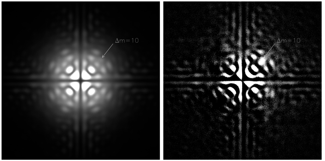
Fig. 6.— Numerical simulation of 2000 coronagraphic frames, obtained under favorable atmospheric seeing (Strehl ratio of 0.94+0.06-0.2) including photon noise (total integration of 1 hour on an mk = 4.9 star with a 3.6 m telescope) and readout noise (5 e− pixel−1 frame−1). A companion 10 mag fainter than the central star is clearly detected at a distance of 3 λ/D(=284 mas on a 3.6 m telescope at 1.65 μm) from the star after subtraction of opposite quadrants as explained in § 4.
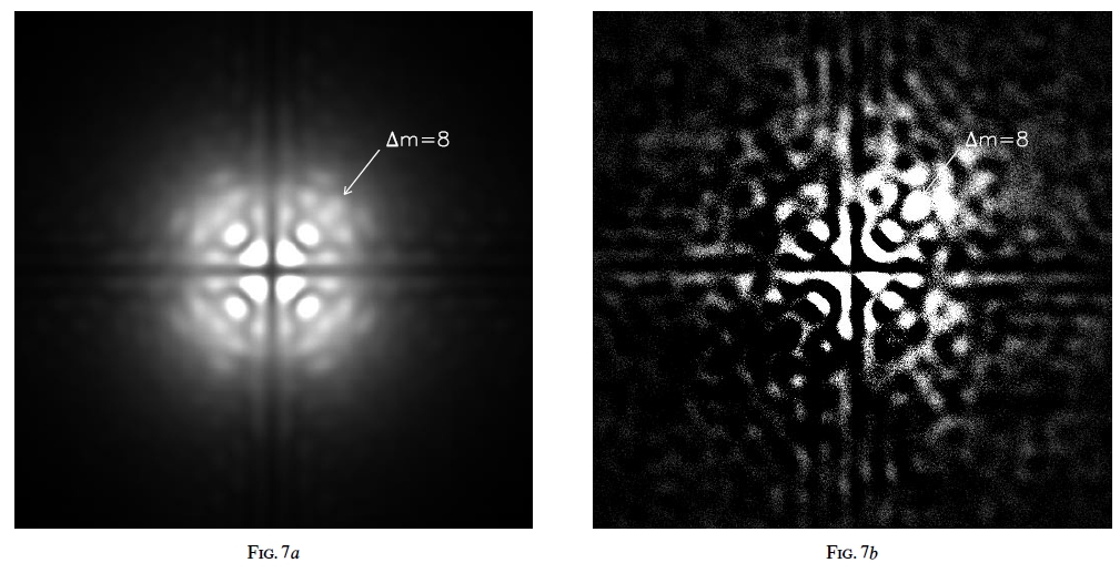
Fig. 7.— Numerical simulation of 2000 coronagraphic frames, obtained with a median Strehl ratio of 0.79 ± 0.2 including a 25% central obscuration and spider arms. Photon noise (total integration of 1 hour on an mk = 4.9 star with a 3.6 m telescope) and read‐out noise (5 e− pixel−1 frame−1) are added to the individual frames. A companion 8 mag fainter than the central star is detected at a distance of 3 λ/D after subtraction of opposite quadrants.
4. DISCUSSION ON LIMITATIONS AND FURTHER GAINS
The manufacturing of the four‐quadrant mask may be critical. First, to minimize the effect of the surface errors at low frequencies (for instance, the gap between quadrants), the Airy pattern has to be enlarged without reducing dramatically the field of view: a large magnification is then used to produce the first image on the FQ‐PM. The mask itself can be simply a transmission plate where a transparent coating is deposited. The difference in coating thickness (e) for two adjacent quadrants is such that (n - 1)e = λ/2. The use of photolithography should allow the deposition of layers of different thicknesses on different areas of the substrate. By using a technique similar to the one developed for antireflection coating, obtaining a precise thickness should not be a huge problem.
In general, one wishes to observe with a broad bandwidth, so a serious issue is the manufacturing of an achromatic π phase‐shift device on an extended wavelength range. By using a multilayer coating with the proper combination of material and thickness, again as done for broadband antireflection coating, we think that such an achromatic mask can be realized with a phase error small enough to be below the residual of the corrected wave front of an AO system. The condition that must be verified by the mask with its different layers is that the quadratic deviation from π of the phase difference be at a minimum in the considered wavelength range. If a is the index for the π phase‐shift quadrants and b for the other ones, and ei and ni(λ) are the thickness and refraction index of layer i, then this condition can be expressed by minimizing the expression
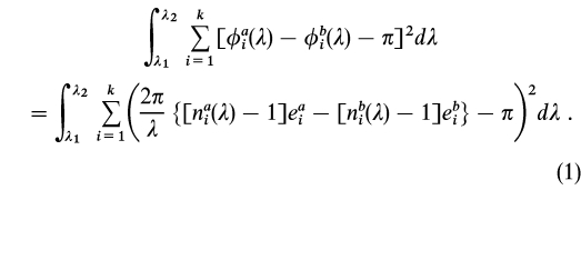
An estimate of the required accuracy can be obtained by considering that the residual due to the device itself must be below the error due to residual random tip/tilt. The phase difference induced by the device (error of thickness or index variation) produces a residual amplitude equal to the phase‐error angle times half the amplitude of the incoming wave. In other words, the relative error on the amplitude is equal to half the phase error expressed in radians. For instance, if the AO system and the seeing allow a rejection factor of 10 mag (thus 10−2 on the amplitude) with a perfect mask, then, for the actual mask, the accuracy on the phase difference between two quadrants must be of 2 × 10⁻² radians (corresponding to a few nanometers in thickness): this does not appear so stringent.
One can also envisage the use of a hybrid mask that will change both the phase with the four‐quadrant mask and the amplitude with a small Lyot mask in the center. Results of our simulations made with this hybrid solution shows a significant reduction of the induced tip/tilt perturbation.
Image processing is another way to improve the rejection rate of the spurious stellar light. One notices that, as long as the phase variance is not too large (i.e., exp iϕ∼1 + iϕ), the speckle image produced with the FQ‐PM is centrosymmetric: this is due to the mask symmetry and its attenuation capability. Such an assumption can be shown by considering the properties of the Fourier transform regarding the parity. We can take advantage of this property when looking for the detection of a faint companion, since it should appear as an asymmetric pattern in the image. If we compute the centrosymmetric image and subtract it from the original image, we then strongly reinforce the contrast of the single feature. This technique was applied in the examples given in Figures 6 and 7.
Other techniques are expected to improve the extinction rate. A first one is the dark‐hole algorithm (Malbet, Yu, & Shao 1995), where a proper correction of the wave front with an active optics can improve the darkening of a small annular field in the coronagraphic image by an additional factor of 10. A second one is the dark‐speckle technique (Labeyrie 1995; Boccaletti, Ragazzoni, & Labeyrie 1998): using exposures shorter than the speckle lifetime, one searches the areas where zero photoevents never occur, even after acquisition of thousands of frames. Depending on the pixel sampling, the dark‐speckle technique may improve the cancellation by 1–3 orders of magnitude. Both techniques, combined with a FQ‐PM, will bring a gain in detection; this will be discussed in more detail in a forthcoming paper.
5. CONCLUSION
We have proposed a new design for a stellar coronagraph based on a variant of the concept of a phase‐mask coronagraph proposed by Roddier & Roddier (1997). Using a four‐quadrant mask with a π phase shift on one diagonal hugely improves the rejection of the light of the on‐axis star and proves to be more easily made achromatic (the mask shape does not depend on the wavelength) and less sensitive to residual tip/tilt of the wave front. In principle, a rejection factor of 20 mag should be possible with a perfect system with no phase perturbation. The device is particularly adapted for a space experiment with a fine correction of pointing error because the space telescope would not suffer from atmospheric turbulence. Then, this coronagraph could be used in an interferometric mode of "densified pupil imaging" (Labeyrie 1996; Pedretti & Labeyrie 1999; Boccaletti et al. 2000). It may become possible to detect giant planets (contrast of 109) far enough from the star and possibly Earth‐like planets with a long exposure time and by subtracting an appropriate reference profile. Obviously thorough simulations have to be undertaken, taking into account the state of the art in terms of residual phase error in a space experiment (achievable smoothness of the telescope mirror, for instance). On the ground, in any reasonable situation, the gain should be much less, but still excellent when combined with an AO system, and reach 8–12 mag depending on the quality of the correction and the existence of a central obscuration. It means that many of the astrophysical programs we quoted in the introduction become feasible. Although the detection of Jupiter‐like planets is still unreachable from ground‐based telescopes, one has to point out the case of extrasolar giant planets (EGPs). According to the nongray theory by Burrows et al. (1997), some EGPs, if observed at a young stage, may be significantly brighter than Jupiter‐like planets. Indeed, EGPs 106 years old, with 3–10 Jupiter masses, could be only 103–104 times fainter than a solar‐type star, and then the dynamic range allowed by the present coronagraph under realistic conditions appears sufficient to directly image such giant planets. The detection of a faint companion (ΔmK = 9,ρ = 2  5) around TWA‐7 (Neuhäuser et al. 2000) tends to confirm this assumption. Although questioned, this candidate could be a young exoplanet (106.5 years old) with 3 times the mass of Jupiter.
Obviously, 51 Pegasi–like planets, orbiting at 0.05 AU from their parent star, are also expected to be very bright, but the required angular resolution is out of reach of current telescopes.
We will present results of more complete simulations of various situations and for most of the characteristics of this new coronagraph in a following paper.