
Abstract
Polymers are widely used materials in aerospace, automotive, construction, medical devices and pharmaceuticals. Polymers are being promoted rapidly due to their ease of manufacturing and improved material properties. Research on polymer processing technology should be paid more attention to due to the increasing demand for polymer applications. Selective laser sintering (SLS) uses a laser to sinter powdered materials (typical polyamide), and it is one of the critical additive manufacturing (AM) techniques of polymer. It irradiates the laser beam on the defined areas by a computer-aided design three-dimensional (3D) model to bind the material together to create a designed 3D solid structure. SLS has many advantages, such as no support structures and excellent mechanical properties resembling injection moulded parts compared with other AM methods. However, the ability of SLS to process polymers is still affected by some defects, such as the porous structure and limited available types of SLS polymers. Therefore, this article reviews the current state-of-the-art SLS of polymers, including the fundamental principles in this technique, the SLS developments of typical polymers, and the essential process parameters in SLS. Furthermore, the applications of SLS are focused, and the conclusions and perspectives are discussed.
Highlights
The fundamental principles in selective laser sintering polymers are reviewed.
The effect of process parameters on the selective laser sintering polymers and the popular polymer materials are discussed.
The recent applications of selective laser sintering polymers and the future works are explored.
Export citation and abstract BibTeX RIS

Original content from this work may be used under the terms of the Creative Commons Attribution 4.0 license. Any further distribution of this work must maintain attribution to the author(s) and the title of the work, journal citation and DOI.
1. Introduction
Polymers are defined as macromolecules formed by the chemical bonding of large numbers of smaller molecules or repeating units, called monomers [1]. Humans have used naturally-occurring polymers to provide weapons, tools, shelter, writing materials, decoration, clothing, and other requirements from the earliest time. Today's polymer industry started in the 19th century when vital discoveries were made to modify specific natural polymers [2]. Polymer materials are essential parts of our life because of their unique chemical and physical properties, including lightweight, good manufacturability, and often elastic properties. However, the applications are also limited by the lower strength and modulus compared with conventional metals and ceramics [3].
Additive manufacturing (AM), also known as rapid prototyping or three-dimensional (3D) printing, is the progress of joining materials to obtain the part from 3D model data, which is often performed layer by layer [4]. A surface tessellation language (STL) file is usually created from a meshed 3D computer model, which can be obtained from acquired image data or parts built-in computer-aided design (CAD) software. Then, a printing file of 2D layers is created by slicing the meshed 3D model and processing it by the machine [5]. AM is based on adding a layer of material together to obtain final parts, which is quite different from traditional manufacturing methods, such as cutting, grinding, and mechanical polishing, which get the desired shapes by subtracting materials. The most popular AM methods are stereolithography (SLA), fused deposition moulding (FDM), laminated object manufacturing, selective laser sintering (SLS), powder bed and inkjet head 3D printing (3DP) [6]. Polymers can be processed by various well-established AM methods, such as FDM, 3DP, SLS, SLA and 3D plotting and others which are still in their infancy and are applied in a few research groups [7]. Each method has unique advantages and disadvantages, and the selection of AM methods depends on the processing materials, accuracy requirements, cost, etc. FDM can process multi-material with good strength and low cost; however, the FDM parts are anisotropic in mechanical properties. A 3DP can process any materials supplied as powders; however, the binder is needed, which easily causes binder contamination. SLA has nano-scale printing resolution; however, only photopolymers can be processed. Since SLS is able to print polymers and composites parts with complex geometry and there is no need to use supports, SLS parts show an excellent capability to prepare end products, making SLS an effective alternative to other AM methods. SLS parts possess high strength, stiffness, and chemical resistance; they can even be used for pharmaceuticals printing because the process is solvent free. This paper will focus on the SLS of polymers based on the authors' previous research experiences in AM.
Dr Carl Deckard and Prof. Joe Beaman at the University of Texas at Austin developed SLS [8] and patented it under the sponsorship of the Defense Advanced Research Projects Agency [9]. It is considered as one of the most famous and rapidly developing AM techniques because of the ability to process various kinds of material, such as polymers, ceramics, metals, and some composites [10, 11]. One of the significant advantages of SLS is that it does not need support structures other than many other AM methods to prevent the built part from collapsing. The un-molten powder works as a supporter in SLS. Therefore, SLS can fabricate complex systems that other AM methods cannot obtain. SLS parts have high strength comparable to original material, which can manufacture highly durable parts for practical applications. Since SLS parts are so robust, it is promising to fabricate various end-use components for automotive and aerospace instead of traditional manufacturing methods like injection moulding. In addition, SLS is a solvent-free process, which is different from SLA and 3DP, and it can print water and organic solvent sensitive materials, such as drug molecules. On the other hand, some challenges exist in the SLS method, especially for the porous surface and low printing speed.
This paper focuses on SLS polymers' state of the art to discuss the fundamental principles of laser sintering mechanism, the influences of process parameters on SLS parts, and popular polymer materials used in SLS. Moreover, the recent applications of SLS polymer parts will also be introduced, considering that there are rapid developments in SLS technology. Finally, conclusions are to be drawn, and the prospective research is also discussed based on state of the art.
2. Selective laser sintering (SLS) method
SLS uses a laser beam to selectively irradiate and solidify the powder material layer by layer to fabricate the designed 3D complex products [12]. Before the laser beam irradiation, the powder material is to be preheated to a high operating temperature. The temperature cannot be higher than the softening temperature points Ts of polymer material; otherwise, powder particles will stick together. The powder material is solidified selectively by further laser heating to the 'sintering temperature'. Sintering occurs with a decrease in the powder temperature, and the surface tensions are to be overcome, resulting in an interfacial kinetic process of the grains. SLS has the basic principles of all AM techniques, e.g. printing layer by layer to fabricate parts directly from 3D model data, and general advantages, e.g. cost-effective, reduced assembly, and feasibility. Figure 1 shows the three steps in the SLS process. A recoating roller first rolls a thin layer of powder material onto the top surface of the building chamber; the laser beam scans a single layer of the designed part. After finishing one-layer scanning, the part piston moves down one layer, and the coating roller rolls another layer of powder on the building chamber surface. The process will be repeated to fabricate the designed part completely.

Figure 1. Schematic diagram of the SLS process.
Download figure:
Standard image High-resolution imageOne of the critical advantages of SLS is the support structures, which are needed in many other AM techniques, such as SLA, FDM, and material jetting, are not necessary because the powder is un-irradiated by laser beam works as support. The support structures are often massive and complex, and they increase the design and manufacturing time. The post-treatment of support structures is also a complex and long-time process. Therefore, the support structures cause lower manufacturing efficiency and higher costs [13], and higher efficiency is possible for the SLS technique compared with other AM techniques. In addition, the fabricated parts are rigid when the SLS process completes because the powder materials are similar to the thermoplastic. Therefore, there is not necessary to wait for the fabricated parts to cool and harden like that after the material jetting process. However, the rapid cooling of the printed parts in SLS easily causes deformation, shrinkage, and warping, which is the principal disadvantage of this method.
3. Fundamental aspects of SLS
3.1. Typical laser sintering mechanisms
Kruth et al classified the sintering mechanisms of SLS/selective laser melting (SLM) into four types: solid-state sintering (SSS), liquid phase sintering (LPS)-partial melting, full melting, and chemically induced binding (CIB) [14, 15]. Figure 2 shows the laser-based powder binding mechanisms. (a) SSS occurs at the temperature below the melting temperature, and the diffusion of particle atoms dominates the sintering process. Necks are formed between adjacent powder particles, as shown in figure 3, to create the binding of powder particles [16]. The tendency to reach lower free energy is the main driving force for sintering. SSS mechanism is only suitable for layer-by-layer laser sintering, such as SLS and SLM. (b) LPS and partial melting has a complex binding process, in which only part of the powder particles is melted. Intense capillary forces are the main driving force to facilitate the liquefied material to spread into the gap between solid particles. Since the flow action of the liquefied material is faster than the solid diffusion, this sintering mechanism allows a much higher laser scanning speed than the SSS [17]. Binder and structural materials are named according to the liquefied and solid-state of powder materials. The binder and structural materials have different physical and chemical properties when existing in the powder material, such as polymer binder versus metallic structural material. However, powder particles can also be sintered by partially melting without distinct binder and structural materials. For example, small powder particles are melted, large particles are remained solid, and the small powder particles work as a functional binder. (c) Full melting sintering occurs when fully melting the metal powders up to a density of 99.9% using a high-power laser [11]. Full melting is suitable for producing almost full dense products in one step, and it also has the drawbacks of high internal stresses and an increased risk of balling formation. (d) CIB utilizes the chemical-induced binding to build parts through chemical reactions involved in the sintering process. The critical application of CIB is the laser sintering of Al powder in the N2 atmosphere, which is commonly used in SLM through the generation of the AlN binder phase to combine the Al particles [18]. Since the binding mechanism is closely related to the powder materials, the four binding mechanisms are not suitable. The SSS is not applicable regarding the SLS of polymers, but the other three mechanisms are important. Moreover, the binding mechanism is also highly dependent on the laser wavelength, energy density, and laser mode.

Figure 2. Laser-based powder binding mechanisms. Reprinted from [15], Copyright (2007), with permission from Elsevier.
Download figure:
Standard image High-resolution image
Figure 3. Image of neck formed between two adjacent powder particles. Reproduced with permission from [14].
Download figure:
Standard image High-resolution image3.2. Laser sintering model
For the binding mechanism of polymer in SLS, the Frenkel sintering model [19, 20] has been put forward to describe the process. The model thinks that the binding process in SLS can be expressed by the sintering of two adjacent particles, as shown in figure 4. The binding model is expressed by the Frenkel–Eshelby model [21]:

Figure 4. Coalescence process of two particles. Reprinted from [21], Copyright (2014), with permission from Elsevier.
Download figure:
Standard image High-resolution imagey(t) is the radius (m) of the neck, a(t) is the radius of the powder particle, as shown in figure 4(a), which are functions of sintering time. σ is the surface tension (N m−1), t is the sintering time, η0 is the apparent Newtonian viscosity of the melt at low shear rates (Pa s). Since the Frenkel–Eshelby model is based on surface free energy and it is assumed that particle radius a is constant, the model is only suitable for the initial sintering stage. Moreover, it is important to obtain the viscosity value under low-stress conditions to be close to the real situation of laser sintering. Poly(methyl methacrylate) (PMMA) and polystyrene (PS) have been used to verify the model experimentally [19]. Figure 4(b) shows the particle coalescence of polyamide 12 (PA12), which can be used to calculate the ratio of neck to particle radius y/a. It is not easy to find two particles with the same radius in the actual SLS process. Therefore, the average of two different radii is often used to calculate the ratio y/a. Equation (1) shows that the coalescence is closed related to two physical parameters of surface tension and viscosity. The change in surface tension is significantly slight for one polymer, but the viscosity can be changed obviously.
When laser sinter (semi-)crystalline polymer powder, the powder temperature is increased to higher than the melting temperature Tm. Since the semi-crystalline polymers have sharp melt points due to a highly ordered molecular structure, they remain solid structure until absorbing a given amount of heat. Then, they change quickly from a solid state to a liquid state. The melted liquid flows into the gaps between powder particles to form sintering necks. A single layer is to be fully molten and overlaps on the previous layer with enough laser beam heat. The viscosity of semi-crystalline polymers must be relatively low compared with the amorphous polymers, resulting in a higher flowing rate of the liquid state, which is very beneficial for the sintering process. The molten powder materials change to the previous semi-crystalline structure when the material temperature cools down below Tm. The important advantages of laser sintering of semi-crystalline polymer are the excellent mechanical and density properties near those obtained from the injection moulding method. However, the shrinkage of laser sintered parts is a severe problem for semi-crystalline polymer because the melted powder materials cool down from melting temperature Tm.
When laser sinter amorphous polymer powder, the material temperature is higher than the glass transition temperature Tg. E (elastic modulus) decreases rapidly when the temperature reaches Tg [22]. Amorphous polymers do not have a sharp melt point due to the randomly ordered molecular structure; hence, they gradually change to a soft structure with a high material temperature higher than the Tg. The liquid state of amorphous polymers has a higher viscosity than semi-crystalline polymers at a similar condition, which causes a lower flowability compared with semi-crystalline polymers. This causes a higher porosity, lower binding degree, and less strength. However, they have a lower shrinkage compared with semi-crystalline polymers. Usually, semi-crystalline polymers are laser sintered in the full melting binding mechanism, and the laser binding of amorphous polymers is conducted in a partial melting binding mechanism. Semi-crystalline polymers usually show better mechanical properties than amorphous polymers [11, 23].
3.3. Processing parameters in SLS
SLS is affected by numerous process parameters, which can be classified into two types of laser parameters and build parameters. Table 1 lists the experimental parameters in SLS. All the experimental parameters should be studied and optimized to get 3D SLS parts with the designed dimensions, handling stability, and good structural and mechanical properties.
Table 1. Experimental parameters in the SLS process.
| Parameter type | Parameter | Definition |
|---|---|---|
| Laser parameters | Laser power | The power at part bed surface from the laser beam. |
| Scan speed | The velocity of the laser beam traverses a scan vector. | |
| Scan spacing | The distance between two neighbouring parallel scans. | |
| Laser beam diameter | The diameter of the laser beam measured at the powder surface. | |
| Build parameters | Layer thickness | The distance of part piston to move down in one layer. |
| Part bed temperature | The controlled temperature of powder in the part bed chamber. | |
| Powder bed temperature | The controlled temperature of powder in the feed bed chamber. |
3.3.1. Laser parameters.
3.3.1.1. Laser power.
Laser power and scan speed are considered two of the most critical laser parameters, and they mainly determine the energy density of laser fill on the powder surface. There are two definitions of energy density by the following equations [24, 25]. The two-dimensional energy density is generally used in the SLS of polymers, although the 3D definition considers the effect of layer thickness:

The flow of melted powder materials is of critical importance for different laser binding mechanisms, which is highly dependent on the energy delivered by the laser beam on the powder surface. Therefore, the energy density with a sufficient level is essential to be applied to increase the temperature of powder materials. High energy density could induce more powder particles to melt, resulting in an increase in the amount of molten polymer. The molten polymer facilitates the adjacent particles to sinter, resulting in increased densification of sintered parts [26, 27]. However, powder degradation and deterioration of mechanical properties of SLS parts have been observed with too high energy density, which caused deteriorated mechanical properties [26, 28]. In the case of SLS PA parts, the relative density, yield strength, Young's modulus, and fracture strength were decreased with a too high energy density [26]. The density and tensile strength of SLS polycarbonate (PC) were also reduced with a too high energy density [28]. The effect of energy density on the mechanical properties of SLS parts will be further discussed in following section 3.4.
The polymer sintering process is closely related to the laser energy density. Figure 5 shows the schematic diagram of different sintering processes depending on laser energy density. Figure 5(A) is the idealized layer sintering with the optimized laser energy. The laser only sinters the top new powder layer and bonds it to the neighbouring layer, and the printed parts have high density and good mechanical properties. With a low energy density, delamination easily occurs due to the poor bonding strength between layers, making the parts weak [29], as shown in figure 5(B). It is impossible to get a high strength part, and the insufficient bond between two neighbouring layers of powder may cause the SLS process to fail because the top layer might be removed during the recoating of new layers. Figure 5(C) shows that warping might occur with excessive laser power. It can be seen that the SLS parts deform due to warping, and the warping can even stop the rolling of new powder layers, failing the SLS process. Balling easily happens in the case of high laser power and too fast scan speed, as shown in figure 5(D), and interrupts near fused powders to form the designed part. Balling effect also hinders the uniform layering of new powder on the previously sintered layer and often leads to cracks, porosity, and rough surface.

Figure 5. Schematic diagram of different sintering processes depending on laser energy density. [30] John Wiley & Sons. © 2009 Wiley Periodicals, Inc.
Download figure:
Standard image High-resolution image3.3.1.2. Scan speed.
The laser supplies the necessary heat for the powder sintering in SLS. A slow scan speed will allow the particles to melt and generate a low surface roughness fully. The coalescence of particles will be limited by a high scan speed, resulting in increased surface roughness. The surface morphology will resemble the initial powder surface due to insufficient particle coalescence. Based on the effect of scan speed on the surface finish of SLS parts, near-infrared (IR) spectroscopy has been used to monitor the effects of scan speed on the sintering process of SLS parts [31]. Reflectance near-IR spectra F(R) were converted to Kubelka–Munk (KM) units using the KM equation [32]:
where R and K are the diffuse reflectance and the absorption coefficient, respectively. S is the scattering coefficient that depends on the particles' shape, size, number, and reflectivity. The scattering coefficient S is the predominant term for the K/S ratio. High scan speed generates a rough surface with high scattering effects, causing a low K/S ratio and decreasing peak intensity. Figure 6 shows the near-IR KM spectra of SLS PA parts at the scan speeds of 800, 1000, 1200, 1400 and 1600 mm s−1 and the laser power of 5 W, which clearly shows the spectra absorbance at the laser scan speed.

Figure 6. Near IR KM spectra of SLS PA parts with different laser scan speeds. [31] John Wiley & Sons. © 2011 Wiley Periodicals, Inc.
Download figure:
Standard image High-resolution image3.3.1.3. Scan spacing.
It has been reported the density, and tensile strength of SLS parts can be increased by decreasing scan spacing [26, 33]. This is because the viscosity of the molten powder decreases, resulting in lower porosity and higher density.
Figure 7 shows a typical laser scan pattern. Since the laser beam radius is always larger than the scan spacing, overlapping between adjacent scan lines exists. The overlap function is defined by the ratio of scan spacing to laser beam diameter:


Figure 7. Schematic diagram of the laser scan pattern. D is laser beam diameter, and HS is scan spacing (hatch spacing). Reproduced with permission from [33].
Download figure:
Standard image High-resolution imagewhere, D is laser beam diameter, and HS is scan spacing (hatch spacing). The same area on the powder surface is irradiated by a laser beam several times due to the overlapping scan paths. The total number of laser irradiation is determined by the following equation, which considers the energy at the laser beam perimeter approaches 0:
In general, smaller scan spacing means more overlap between adjacent scan lines, and larger scan spacing indicates more extensive penetration of scan lines toward the previous layer. The shrinkage ratio of SLS parts increases with increasing the scan spacing in a specific range, and it will grow to be flattened with significantly large scan spacing [34].
The part orientation, scan spacing, outline laser power, and laser fill powder were verified as essential process parameters in the SLS process of hydroxyapatite (HA)/poly- -caprolactone scaffolds [35]. Part dimension was found to increase quadratically with decreasing scan spacing. It was anticipated that the interaction effect between laser fill power and scan spacing was significant because they determined the delivered energy density. This interaction effect significantly influenced the part dimensions obtained in the z-direction. However, scan spacing greatly impacted all x, y, and z-direction.
3.3.1.4. Laser beam diameter.
Laser beam diameter is closely related to the thermal flux input to the powder surface, which significantly influences the powder binding process and polymer degradation [37]. The thermal flux input to the powder surface is reduced with increasing the laser beam diameter when the laser power and scan spacing are fixed. However, every surface point will receive a more significant number of discrete laser pulses. Therefore, the thermal rise time of the single-layer increases and the maximum temperature decreases. Vail et al [36] found that the green strength of SLS parts was increased with increasing the laser beam diameter, which is possible due to the lower polymer degradation at a larger beam diameter. Figure 8(a) shows that the predicted polymer content of a single layer of copolymer coated silicon carbide powder increases with increasing the laser beam diameters. The thermal penetration is improved by increasing the laser beam diameter, which is partly responsible for the increased bend strength observed experimentally with increasing the beam diameter [38, 39]. Based on the calculation results of Vail et al [36], experimental verification was performed to explore the effect of laser beam diameter on the SLS process [33]. It was confirmed that density and strength were increased with increasing the laser beam diameter, and a larger beam diameter also decreased the average thermal gradient to decrease. The effect of laser beam diameter contributes to the different irradiation intensity distribution within the irradiated spot. A large beam diameter causes a larger area for less intense laser irradiation and is more uniform. Figure 8(b) shows that the average density of the SLS part is increased with a larger laser beam diameter.

Figure 8. (a) Predicted polymer content of a single layer of copolymer coated silicon carbide powder with different laser beam diameters. One horizontal axis unit corresponds to a laser beam diameter of 230 μm. The 'Key' parameter is laser energy density. Reproduced with permission from [36]. (b) The experimental average density of SLS parts with different laser beam diameters. The SLS material was bisphenol-A PC. Reproduced with permission from [33].
Download figure:
Standard image High-resolution image3.3.2. Build parameters.
3.3.2.1. Layer thickness.
Layer thickness significantly influences the building time and surface roughness of SLS parts. The surface roughness is to be improved by decreasing the layer thickness; however, the building time is longer. The layer thickness is mainly determined by the penetration depth of the laser beam into the powder, which is closely related to the compaction, thermal conductivity, powder density, particle size, energy density, and specific heat of the material [3, 24]. Low melting of a single layer can cause microstructure defects, such as un-molten particles and porous structures [40]. Figure 9 shows that the un-molten inner region of particles generated due to the heat from laser irradiation did not fully supply enough heat to melt a single layer [27]. However, unwanted part growth in the building direction can occur when the laser penetration depth is much larger than a layer thickness and additional powder past a powder layer is molten [41].

Figure 9. Microstructures of SLS parts with the powder materials of (a) Duraform PA and (b) Innov PA. The laser energy density were (a) 2.04 J cm−2 and (b) 1.70 J cm−2. Reprinted from [27], Copyright (2012), with permission from Elsevier.
Download figure:
Standard image High-resolution imageThe layer thickness is also closely related to the shrinkage of SLS parts. A feedforward neutral network model is used to explore the functional connection between the SLS process parameters and the shrinkage ratio of SLS parts [34]. Figure 10 shows the relationship between the layer thickness and the shrinkage ratio. The shrinkage ratio decreases rapidly with increasing the layer thickness at the initial stage; however, the shrinkage ratio curve is nearly flattened with the layer thickness larger than 0.2 mm. This might be because the degree of sintering decreases when the layer thickness increases in a given range, the degree of shrinkage tends to be stationary when the layer thickness is above the given range.
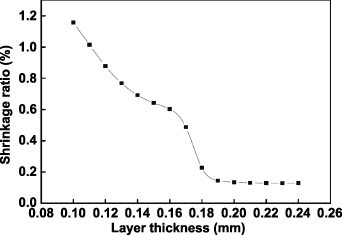
Figure 10. The shrinkage ratios with different layer thicknesses. Reprinted by permission from Springer Nature Customer Service Centre GmbH: Springer Nature, International Journal of Advanced Manufacturing Technology [34], © (2007).
Download figure:
Standard image High-resolution image3.3.2.2. Part/powder bed temperature.
The set of part bed temperature is dependent on the types of powder materials: amorphous and semi-crystalline, and the powder bed temperature is usually set to be slightly lower than the part bed temperature. Figure 11 shows the relationship between polymer volume and temperature for different polymers. Amorphous polymers only have a glassy transition temperature Tg and do not have a melting temperature Tm. Amorphous polymers show a leathery or rubbery state with a temperature higher than Tg, and the softening temperature Ts of an amorphous polymer is Tg. Therefore, the setting of part bed temperature for amorphous polymers should be lower than Tg. On the other hand, the required laser power can be decreased with a high part bed temperature, and the high part bed temperature can also reduce the difference between the in-sintering and after-sintering temperature. Hence, the part bed temperature is normally set to be lower and close to Tg for the SLS of amorphous polymers. Figure 11 shows that semi-crystalline and crystalline polymers do not have a Tg and have a Tm. Therefore, the part bed temperature can be slightly lower than the Tm for the SLS of semi-crystalline and crystalline polymers. In reality, crystalline polymers do not exist, and most of them perform in the form of semi-crystalline and have both Tg and Tm.

Figure 11. Relationship between polymer volume and temperature for different polymer types. Reproduced with permission from [24].
Download figure:
Standard image High-resolution imageSince semi-crystalline polymers are typically used as SLS powders, the typical SLS powder of semi-crystalline polymer PA12 is discussed. Figure 12(a) shows the typical differential scanning calorimetry (DSC)-Thermogram of PA12 powder material for SLS with the nature of 'sintering window' [42]. Crystallization of powder should be inhibited during the sintering process as long as possible to reduce warpage and shrinkage. The crystallization occurs in a temperature range described with onset crystallization temperature Tc,onset, peak crystallization temperature Tc,peak, and offset crystallization temperature Tc,offset. The polymer will crystallize quickly with a temperature lower than Tc,onset, resulting in curling and warping of SLS parts. Hence, the part bed temperature needs to be higher than the onset crystallization temperature Tc,onset. In addition, the part bed temperature should also be lower than the Tm to avoid sticking powder. Therefore, part bed temperature should be controlled precisely between the Tc and Tm. This meta-stable thermodynamic region is called the 'sintering window' of the SLS process. There are no stresses in part during the SLS process, resulting in no part warpage. The fabricated parts easily curl when part bed temperature is too close to the Tc due to premature crystallization. However, with a too high temperature close to Tc, powder material in the vicinity of particles irradiated by laser easily stick on the molten surfaces (lateral growth), leading to a loss of designed part features. Figure 12(b) shows the viscosity loss of PA12 (semi-crystalline) and acrylonitrile butadiene styrene (ABS) (amorphous). When heating the semi-crystalline to higher than the melting point, the viscosity decreases dramatically due to the high chain mobility. However, the viscosity of amorphous polymers decreases gradually with the temperature higher than the glassy transition point. This may make the SLS process more complex and challenging because a small fraction of particles can flow at more variable and lower temperatures, inhibiting powder flow through the part bed [21].

Figure 12. Typical DSC-Thermogram of PA12 powder material and viscosity loss of ABS and PA12. Reprinted from [42], Copyright (2016), with permission from Elsevier. Reprinted from [48], Copyright (2010), with permission from Elsevier.
Download figure:
Standard image High-resolution image3.3.3. Other parameters.
The particle size and morphology are also crucial parameters in SLS [27], and they have a significant influence on the powder flowability and powder bed density [26, 43]. The powder bed density directly translates to the density of the green part [44], and powder flowability is considered a critical parameter for powder density and part density [45, 46]. To increase the powder bed density and flowability, a specific particle size distribution (PSD) and good sphericity are generally required for SLS powder [47]. Commercial SLS powder with good flowabilities normally consists of spherulite particles with a low share of fine particles below d= 10 μm and a narrow size distribution of d= 60 μm [48].
The particle size has been verified to affect the density of PS parts fabricated by SLS [49]. The part density increased with decreasing the particle size. However, the powder particles will self-reunite with a significantly small size, and this can cause problems in spreading the powder polymer. The particle size of 75–100 μm is suitable for the SLS process considering the part density, the cost of milling powder, and the process of spreading the powder in SLS. The commercial PSD is usually located in the range of 20–80 μm.
The fraction of small particles is often neglected during the measuring process. However, the tiny particles are often responsible for SLS powder quality. This is because small particles could cause binding between larger particles because of their easily melting properties. If a high fraction of small particles is neglected, the SLS process with the powder may fail due to stickiness in the powder caused by the small particles [42]. The porosity distribution and pore size were studied by SLS of two different PA12 powders, Duraform PA and Innov PA, and it was found that the granulometry distribution can demonstrate the difference in the porosity formation to some degree, as shown in figure 13 [27]. The smallest particles are molten even with low energy density, and the molten material promotes welting between layers, resulting in part influence in the sintering process. Bellehumeur et al [19] reported no significant effect of the geometry of particles on the sintering rate, which increases with decreasing the viscosity of particles. However, less particle size decreases this effect.

Figure 13. Schematic diagrams of porosity formation with different granulometry distribution. (a) Duraform PA and (b) Innov PA. Reprinted from [27], Copyright (2012), with permission from Elsevier.
Download figure:
Standard image High-resolution imageThe flowability of powder material has to be high and enable the powder to be rolled uniformly at a high temperature determined by powder/part bed temperature with a thickness of about 100 μm. The powder flowability can be evaluated by many techniques, such as bulk/tap density (ASTM D 7481) and angle of response (DIN ISO 4324) [50]. Since each method is strongly dependent upon the powder stress condition and no approach had been established for SLS powder, 'Round Robin Tests' was proposed to evaluate the flowability of SLS powder [51]. Four different SLS materials were investigated regarding powder flowability based on a Round Robin Test, which demonstrated the simplified procedure of determining tap and bulk density is adequate to quality and distinguish between various powders.
The polymer molecular weight was found to influence the quality of SLS parts through the melting viscosity [49]. The melting viscosity η0 can be expressed by the Mark–Houwink equation [52]:

where, k and n are empirically determined constants and depend on the particular polymer-solvent system, which can be obtained by measuring the viscosities and molecular weights and fitting the best straight line. Mw is the average molecular weight of the polymer and can be calculated by equation (8). wi is the weight fraction of molecules which has the molecular weight Mi .
Niino and Sato investigated the influence of powder compaction on the SLS parts with the PA powder and PS powder [53]. As an advantage, the mechanical strength was increased because the residual porosity of SLS parts was reduced by a factor of 30%. However, the accuracy of SLS parts was decreased due to increased excessive sinter, especially in SLS of an amorphous polymer. Figure 14 shows the curl distortion measurement photos of SLS PA parts without and with powder compacting [53].

Figure 14. Curl distortion measurement photos of SLS PA. Parts (a) and (b) are a top view and side view, respectively. Reproduced with permission from [53].
Download figure:
Standard image High-resolution image3.4. Mechanical properties of SLS parts
Many SLS factors, e.g. orientation and fabrication position, post-processing, fabrication parameters, and powders, influence the mechanical performances of SLS parts. Gibson and Shi investigated the influences of SLS factors, such as SLS process parameters, powder materials, fabrication position, and post-processing, on the mechanical properties of SLS parts [24]. With the optimized SLS process parameters, the mechanical properties are mainly determined by selecting powder material. The same powder material changes mechanical properties by verifying process parameters, fabrication position, and orientation. Caulfield et al [26] studied the influences of laser energy density and building orientation on the mechanical properties of SLS parts with the material PA, as shown in figure 15. The part dimensions increased with an increase in the energy density because the high energy density caused more powder material to be melted, resulting in extra part dimensions in width and thickness. The shrinkage of parts due to cooling can be decreased by increasing the energy density because the part density increases. This is because there is a larger irradiation area in each layer with the 0° orientation building, resulting in an improvement in particle fusion and higher density. Moreover, the 0° orientated parts have a serrated fracture, as shown in figure 15(b), because the stress is applied along with each layer, and fracture occurs at different weak areas. However, the 90° orientated parts fracture in the direction perpendicular to the force, as shown in figure 15(c), because the force is perpendicular to each layer.

Figure 15. (a) Fracture strength values with different part building orientations. Coloured lines indicate layer interfaces. (b) Actual fracture of a 0° oriented part with an energy density of 0.01968 J mm−2. (c) Actual fracture of a 90° oriented part with an energy density of 0.007754 J mm−2. Reprinted from [26], Copyright (2007), with permission from Elsevier.
Download figure:
Standard image High-resolution image3.5. Polymer degradation in SLS
Ho et al [28, 54] investigated the polymer degradation during the SLS of PC. Smoke could be seen when the PC parts were sintered with an energy density higher than 0.09 J mm−2, which indicated the degradation of PC powder material. Therefore, the density was decreased with increasing the energy density of higher than 0.09 J mm−2, as shown in figure 16(a). Figures 16(b) and (c) show that the irregular shape of voids on the fractured cross-section changed to a spherical structure with increased energy density from 0.094 to 0.10 J mm−2. Since the fusion of particles becomes sufficient with increasing the energy density, the irregular voids change to spherical voids because of the surface tension of the molten powder. Moreover, the spherical voids show a more significant number and diameter with increasing the energy density from 0.10 to 0.12 J mm−2. The reason could be explained that smoke or gases generated due to the degradation process with a high energy density, which mainly occurred on the layer surface due to the direct contact between laser beam and powder material. However, some smoke or gases would also generate under the surface of the layer because the laser beam penetrates the powder particles. They would be trapped when the voids are sealed off quickly due to the efficient melting of the powder with high energy density. Other researchers have also reported similar result that the density of SLS parts decreases with a significantly high energy density [55, 56]. The powder temperature increases by increasing the energy density, resulting in lower melt viscosity and a higher sintering rate. Consequently, the density of SLS parts increases. However, degradation of polymer materials occurs with significantly high energy density. Hence, the density drops due to severe material degradation. In addition, it should be noted the dimensional accuracy of SLS parts will decrease with a significantly high energy density, mainly due to the rapid part growth.

Figure 16. (a) Densities of PC parts with different energy densities. Parts (b)–(d) are the cryogenically fractured cross-sections of PC specimens built under an energy density of 0.094, 0.10 and 0.12 J mm−2, respectively. The loading direction is perpendicular to the scanning direction. Reprinted from [28], Copyright (1999), with permission from Elsevier.
Download figure:
Standard image High-resolution image3.6. Influence of aged powder on SLS part
Many researchers have investigated the influence of the ageing behaviour of powder on the SLS parts. The melt flow ability of aged powder decreases due to the increased molecular weight caused by a possible 'cross-linking' between the polymer molecules [57, 58]. This effect on the SLS parts causes undesirable mechanical properties and deteriorated surface finish [59]. PA12 powders in different ageing histories, virgin, aged-virgin mixed, and in-process aged powder, were used to study the effect of in-processing ageing of polymer on coalescence behaviour in SLS and the mechanical properties of SLS parts [60]. Figure 17(c) shows that nucleation is possible in some fine spherulitic regions in an amorphous matrix during the SLS process for virgin and aged powder. When the temperature is lower than Tm, the nucleation of virgin powder completes due to the first crystallization phase in the amorphous region [61]. Since there is a limitation in the number of nuclei in the amorphous region, the rings grow from the limited potential sites. Finally, figure 17(a) shows fine fibrillar spherulitic regions appear with some regions of the amorphous matrix. In addition, melt viscosity increases due to increased molecular weight, which will cause lower laser coalescence between particles [62–64]. Lower tensile strength and/or elongation have been reported with aged powder than that obtained with virgin powder [62, 64]. In the case of aged powder, higher melting point pieces generate a more significant number of nucleation compared with virgin powder. Because of sufficient nucleation positions, spherulites easily nucleate before forming in three dimensions [65]. Then, the coarser appearance of spherulites forms and spreads all over the polymer matrix, as shown in figure 17(b).

Figure 17. Scanning electron microscope (SEM) images of single layer printed from (a) virgin and (b) aged PA12 powders. (c) Schematic crystallization mechanisms and consequential microstructures with different powders. Reprinted from [60], Copyright (2017), with permission from Elsevier.
Download figure:
Standard image High-resolution image3.7. Recycling of SLS power
About 70% of SLS powder has not been sintered and remained after the sintering process. The aged powder is usually recycled by refreshing with new powder due to the high price of new powder. A recycling process was developed by Weinmann et al to reverse the aged SLS powder [66]. A chemical agent is added to the used powder; it is able to cleave the long polymer chains of the used powder at its amide bonds. The flow properties of the used powder can be adjusted selectively depending on the kind of chemical agent and its concentration, which also makes the quality of these mixtures reproducible. Wang et al processed the used powder into filaments for extrusion-based AM, providing an opportunity to recycle used SLS powder [67]. A milled carbon (MCF)/recycled PA (rPA12) composite filament was developed to be used for extrusion-based AM. The measured DSC demonstrated that the MCF did not significantly change the melting temperature, crystallization temperature or crystallinity of rPA12. A morphological study on the fracture surface of the composites, as shown in figure 18, revealed that there was medium interfacial interaction between the MCF and PA12, which improved the flexural and tensile strength of PA12.

Figure 18. Observation of recycled PA12 and its composites. Reprinted from [67], Copyright (2018), with permission from Elsevier.
Download figure:
Standard image High-resolution image3.8. Advanced selective sintering methods
Some advanced selective sintering methods, such as electrophotographic multi-material SLS, multi-jet fusion (MJF), and selective inhibition sintering (SIS), were developed to improve the low sintering rate and single powder material limitation within a building process of the SLS method.
3.8.1. Multi-material SLS.
A single material is usually used in commercial SLS machines; Kumar et al proposed a multi-material method, a powder-based freeform fabrication technology that fabricates 3D parts by sintering powder layer-by-layer with electrophotography and thermal fusing [68–70]. A printing machine was developed from an electrophotographic printer. A mixed powder based on 5 μm styrene particles was used with various additives like ferrous oxide. The parts were printed with an average rate of roughly 5 μm per print and had heights of roughly 1 mm. There is a limitation in height because the printed or fused powder layers on the transfer electric field influence the SLS process.
Kumar et al also tried to replace the roller device with an array of hopper-nozzle that can directly write dots, lines, and patterned regions of multiple powder materials [71, 72]. Powder materials can be delivered continuously with the flow of fine powders from small scale hoppers due to gravity, and the used spherical powder particles are in the 63–125 mm range. Beverloo's correlation can be used to calculate their flow rates. Different patterns deposited under gravity flow with hopper-nozzles are shown in figure 19.

Figure 19. Different patterns deposited under gravity flow with hopper-nozzles. Reproduced with permission from [72].
Download figure:
Standard image High-resolution image3.8.2. Multi-jet fusion (MJF).
MJF is a proprietary method of Hewlett-Packard (HP) Inc. and was first proposed in 2014. SLS uses a laser to heat the powder, but MJF uses IR lamps to heat the powder in the designed area which is treated with a fusing agent. The fusing agent makes the irradiated area can absorb IR radiation energy and is applied by inkjet nozzles. At the same time, a water-based detailing agent is supplied along the contours of the printed parts, and it can stop the powder near the contours from fusing, which can improve the printing accuracy, as shown in figure 20. The detailing agent can also be applied in specific areas within the designed parts, improving the thermal distribution in the printed area.

Figure 20. Schematic illustration of the MJF process. Reprinted from [73], Copyright (2021), with permission from Elsevier.
Download figure:
Standard image High-resolution imageCai et al compared the mechanical properties of PA12 printed by SLS and MJF [73]. For the X and Y orientations, the tensile strength was almost the same for the two powder materials, but the tensile strength in the Z orientation was ∼25% higher with the MJF printed specimens. In addition, the surface finish was better with the MJF specimens, but the top surface was rougher. Conor and Dowling compared the material properties of PA and glass bead filled PA printed by the MJF method [74]. It was found that there was almost no difference in the chemical functionality and the thermal properties of the printed parts with two powder materials.
3.8.3. Selective inhibition sintering (SIS).
SIS is a new AM method in which the particles at the boundary of the part are prevented from binding with each other [75, 76]. The first SIS step is the same as the SLS method, rolling a new powder layer on the previous layer figure 21(A). Then, the specific areas of the new layer surface are processed by a printer for sintering inhibition (B). The powder layer outside the part envelope is prevented from radiating by placing a radiation minimizing frame (C). An IR heater is used to supply thermal radiation to sinter the entire layer (D). At last, a block is sintered except for those areas processed by the inhibitor (E). The printed part can be easily separated from the surrounding powder (F).

Figure 21. Schematic illustration of the SIS process steps (A)–(D) and extracting the fabricated parts (E) and (F). Reproduced with permission from [76].
Download figure:
Standard image High-resolution imageA potassium iodide salt solution was used as the inhibitor [77]. Most of the salt liquid evaporated after the SIS process, and a thin salt layer remained in the processed area. Then, the residual salt wall can be removed by water.
3.8.4. Selective oil sintering.
A selective oil sintering method was developed to increase the printing speed, in which hot oil droplets (175 °C) were used as a fusing agent to bind the powder material [78]. The hot oil droplets of approximately 2000 μm were extruded from a glass dropper, as shown in figure 22. The designed parts were printed by sintering the powder material with many tiny droplets from the multiple glass droppers. The hot oil droplets moved along the X and Y axes of the powder surface, to which powder layers were rolled. This method can obviously increase printing speed by finishing all the processes in one step.

Figure 22. Schematic illustration of the selective oil sintering process. Reproduced from [78]. CC BY 4.0.
Download figure:
Standard image High-resolution image4. Materials used in SLS
4.1. Engineering polymers
Engineering polymers are materials with superior structure-property correlations [79]. They are classified into: thermosetting, thermoplastics, and elastomers [80]. Thermoplastic parts fabricated by SLS show mechanical and material properties similar to those obtained with conventional methods [81]. Furthermore, the SLS method has the advantage of design flexibility. PA12 and PA11, filled systems, and other thermoplastic materials such as polypropylene (PP) are the most commercial SLS powder materials [42]. Therefore, thermoplastics are normally used in SLS. The types of polymers used in SLS are limited to a small number: including polyamide (PA11 and PA12), some PC, PS, and variants of those [49]. Nylon is the most widely used material in SLS [82, 83]. Some semi-crystalline polymers, such as polyethylene [84, 85], polycaprolactone (PCL) [86, 87], and polyetheretherketone (PEEK) [88, 89] are getting more and more attention. Figure 23 shows the possible thermoplastic materials used for SLS.
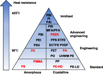
Figure 23. Triangle of amorphous and semi-crystalline materials, in which the red materials can be used for SLS.
Download figure:
Standard image High-resolution image4.2. Desired properties of SLS polymers
There are two critical requirements for the maximum suitability of a polymer to be used in SLS [27, 90]. The processing window between the melting and crystallization temperature should be as wide as possible, enabling the crystallization process to occur sufficiently slowly to reduce part warpage during the SLS process. On the other hand, a high enthalpy is also essential to less melt powder particles in the vicinity of the particles irradiated by the laser beam. The vicinal particles are heated due to heat conduction even if not irradiated by laser directly. In addition, a narrow melt temperature range and low melt viscosity are also crucial for SLS materials to flow quickly in a liquid state without inputting excess energy.
Figure 24 shows the intrinsic and extrinsic material properties required for LS-powders. The intrinsic properties include thermal properties, rheological properties, and optical properties, and they are closely dependent on the molecular structure of the polymer material, which are difficult to be changed. The extrinsic properties are determined by the production process of powder. Sine powder for SLS needs to meet many intrinsic and extrinsic properties. The available types of powder are still minimal, as shown in figure 23.

Figure 24. Intrinsic and extrinsic material properties required for LS-powders. Reprinted from [42], Copyright (2016), with permission from Elsevier.
Download figure:
Standard image High-resolution imageThe viscosity and surface tension of polymer should be low enough for SLS processing to generate adequate coalescence of powder particles. Since SLS is carried out without additional compacting, low melt viscosity is critical for particle coalescence. Absorption, transmission, and reflection occur when a laser beam radiates to the powder surface. The powder material should be able to absorb radiation of the used laser wavelength efficiently, which generates enough energy for the binding process. Since most polymers have some group vibrations in the 'fingerprint' IR region, they are effective in absorbing 10.6 μm CO2 laser radiation. This is also the reason that a 10.6 μm CO2 laser is widely used for the SLS process. Moreover, the transmission part of a laser beam into the polymer, which provides sufficient radiation energy in deeper regions of the powder bed, is important for binding between adjacent layers without layer delamination.
4.3. Comparison between SLS amorphous and semi-crystalline parts
Generally, the properties of amorphous and semi-crystalline parts fabricated by SLS have quite different mechanical properties and dimensional accuracy, as shown in table 2. The SLS part's relative density (ρr) can be defined as the following equation:
Table 2. Comparison of amorphous and semi-crystalline parts fabricated by SLS.
| Part properties | Relative density | Strength | Dimensional accuracy |
|---|---|---|---|
| PS (amorphous) | Low | Low | High |
| PA12 (semi-crystalline) | High | High | Low |
where, ρf is the full polymer density, and ρ is the SLS part density. Compared with the polymer material with full density, the SLS amorphous parts have very low relative density and much lower tensile strength. However, the relative densities of SLS semi-crystalline parts are higher, and their tensile strength is close to the strength of the fully dense parts.
4.3.1. Comparison of mechanical properties.
The relative density of SLS parts is mainly determined by the sintering rate of powder particles and part bed fractional density. The part bed fractional density in the SLS ranges from 0.4 to 0.6 [78] and is closely related to particle size, particle shape, and PSD. Since the part bed fractional density changes in a small range, it has less effect on the relative density of the SLS part. Therefore, the sintering rate in SLS plays a crucial role in the high relative densities of SLS parts. According to the Frenkel–Eshelby model shown in equation (1), the initial sintering rate of polymer is determined by the surface tension and the apparent Newtonian viscosity of the melt at low shear rates. The surface tension is very low and changes little with the temperature for most polymers. Hence, the initial sintering rate is mainly affected by the apparent Newtonian viscosity of the polymer, which is in inverse proportion to the initial sintering rate. The viscosity of an amorphous polymer usually has a much higher viscosity than that of a semi-crystalline polymer. Hence, the higher viscosity of amorphous polymer causes a lower initial sintering rate in the SLS process compared with semi-crystalline polymers, according to the Frenkel–Eshelby model. Therefore, a higher relative density of semi-crystalline part obtained from SLS is expected compared with the amorphous part obtained from similar conditions. The differences in the relative density of SLS parts of typical amorphous PS and typical semi-crystalline PA12 were studied by Yan et al [55], and the relative density of PS is higher than the PA12 with the same energy density.
4.3.2. Comparison of dimension accuracy.
The dimensional accuracy of SLS parts is mainly determined by the volume shrinkage in sintering densification and the volume shrinkage in phase transition [55]. Semi-crystalline polymers usually have more significant phase transition shrinkage than amorphous polymers. Moreover, sintering necks only form at the contact area between the adjacent particles during the SLS of amorphous polymers; the relative position between particles changes slightly with many voids. Therefore, the volume shrinkage of amorphous polymer in sintering densification is minimal. In contrast to amorphous polymers, volume shrinkage during sintering densification is more significant for semi-crystalline polymers because loosely packed powders are finally sintered into near-fully dense parts. Hence, the dimensional accuracy is higher than that of semi-crystalline polymers due to less total volume shrinkage.
4.4. SLS of different polymers
The SLS process of typical polymers, such as PA, PC, and PS, and some popular polymer-based composites are to be introduced in this section.
4.4.1. SLS of polyamide (PA).
PA parts from SLS have been widely used for functional applications in the biomedical, automotive, and aerospace industries [79]. They are a family of polymers with amide groups to link repeating units together. PA12 almost entirely dominates the PA powder market due to the perfect SLS properties, especially a relatively large temperature interval between the onset of melting and crystallization [41]. Verbelen et al [91] characterized the laser sintering properties of four commercial PA sintering grades. Figure 25 shows the dependence of DSC on different maximum heating temperatures for four commercial PA sintering grades. PA12-PA2200 shows the crystallization onset is postponed significantly with increasing temperature. Post condensation reactions were raised with a higher temperature to increase melt viscosity and molecular weight, resulting in slower crystallization kinetics. PA11-Rilsan and PA6-Sinterline show a similar tendency. However, there is no change in the crystallization position for PA12-Orgasol, indicating no post condensation reactions. Moreover, all PAs have significantly shaped melting peaks with high enthalpies due to the high crystallinity.

Figure 25. Relationship between DSC and heating temperatures for (a) PA12-PA2200, (b) PA12-Orgasol, (c) PA11-Rilsan and (d) PA6-Sinterline. Reprinted from [91], Copyright (2016), with permission from Elsevier.
Download figure:
Standard image High-resolution imageThe fatigue behaviour of plain and notched SLS and injection moulding parts with PA12 was studied by van Hooreweder and Kruth [92]. When the SLS parameters were optimized to obtain near full-dense parts, there were no differences in mechanical properties and equal intralayer and interlayer fatigue strength were observed. Moreover, the building orientation of SLS parts does not influence the fatigue properties, and injection moulding parts show the same fatigue properties as the SLS parts. Fatigue properties were analysed with a closed-loop servo-hydraulic test rig [93]. Figures 26(a) and (b) show the fracture surfaces, indicating a brittle and ductile fracture surface. Unfused powder particles were observed in both tensile and fatigue text specimens, as shown in figures 26(c) and (d).

Figure 26. Fracture surface of SLS-PA12 parts after (a) tensile test and (b) fatigue test. The amplified fracture surface of the tensile test (c) and fatigue test (d). Reprinted from [93], Copyright (2010), with permission from Elsevier.
Download figure:
Standard image High-resolution image4.4.2. SLS of polycarbonate (PC).
PC is a common and low-cost amorphous polymer. SLS PC parts are usually difficult to use as functional parts due to the poor mechanical properties related to high porosity. Since epoxy resin has a similar molecular structure to PC, Shi et al tried to infiltrate SLS PC parts with epoxy resin [94]. Due to capillarity, the epoxy resin infiltrates into the SLS PC parts, resulting in cavities filled with resin. Then, the mechanical properties of SLS PC parts were significantly improved due to the curing agent of epoxy resin. Volume shrinkage of SLS PC parts is observed due to epoxy resin curing. The movement of PC powder during SLS was studied by different scan sintering [95]. Figure 27 shows the top view of solidified melt pools with varying lengths of time. The spherical shape of melt pools can be observed due to the surface tension of the molten polymer and some melted PC particles attached to the lower surfaces of melted pools. The melted pool at 180 s shows the sign of a burst air bubble. Air or gases were trapped in the melted polymer to form bubbles. The void spaces between the particles underneath the surface contracted, pushing the air upward when densification of the PC powder continued [54, 96]. Finally, the bubbles burst and released the inside hot air.

Figure 27. SEM micrographs of the solidified PC melt pools with different lengths of time, scale bar is 500 μm. Reproduced with permission from [95].
Download figure:
Standard image High-resolution image4.4.3. SLS of polystyrene (PS).
A single-layer method was used to investigate the SLS of PS [97]. The higher part bed temperature of 100 °C improved the polymer coalescence due to the homogeneous and smooth surface without individual tracks. However, the addition of carbon black (CB) reduced the consolidation of a single layer. The thermal conductivity of the powder bed is increased by the CB addition [98]. In addition, laser absorption in the black-coloured powder bed increases with limited laser penetration depth [48, 99]. Therefore, the increase in temperature by the laser is completed in a shorter time due to the increased powder bed conductivity, resulting in a shorter period of viscosity decrease, hindering the effect on the coalescence between laser tracks. The pore shape of the SLS PS parts was irregular with an energy density of 0.4 J mm−2, as shown in figure 28(a), due to the inadequate fusion of powder. With increasing the energy density, the pore shape changed to a spherical shape, as shown in figure 28(b), because the powder material was burnt with a high energy density of 0.53 J mm−2, which can be inferred from the observed smoking during SLS [100].

Figure 28. Observation of pore shapes with the energy densities of (a) 0.4 J mm−2 and (b) 0.53 J mm−2. Reprinted by permission from Springer Nature Customer Service Centre GmbH: Springer Nature, Journal of Materials Engineering and Performance.
Download figure:
Standard image High-resolution imagePS is widely used to prepare investment casting patterns through SLS due to lower shrinkages with the low thermal expansion than semi-crystalline polymers. DTM CastFormTM PS is an investment casting pattern material which can be used as SLS powder with a glass transition temperature of 89.8 °C. The microstructure development of carbon fibre (CF) in SLS has been investigated with different energy densities, and red wax is infiltrated into the porous SLS parts to improve the mechanical properties successfully [101]. Dotchev et al [102] also studied the factors affecting the accuracy of the CF patterns used for investment casting. The part shrinkage is linear with the X and Y directions during the SLS process and wax infiltration. The wax infiltration causes additional errors in the X and Y direction. However, the post-infiltration partly compensates for the dimensional error in the Z-axis although introducing new non-linear shrinkage.
4.4.4. SLS of polyetheretherketone (PEEK).
PEEK is a suitable polymer for the aerospace, automotive, and chemical industries due to its good mechanical properties and performance at high temperatures. PEEK is also ideal for medical devices and implants application due to its excellent biocompatibility with the introduced hydroxylic groups [103]. However, the SLS of PEEK is still in its infancy, which is quite different from the commercial applications of SLS of PA or PS. PEEK is usually manufactured using conventional injection moulding, extrusion, and computer numerical control methods. Schmidt et al studied the SLS of functional and individual PEEK parts which were different from previous zero load-bearing parts for tissue engineering (TE) [89]. The laser-sintered parts could be used for non-resorbable implants due to their biocompatibility and load-bearing. The main process window was found by considering the preheat temperature and input laser energy, and the porosity could be improved from 15% to nearly zero.
Rechtenwald et al [104] studied the minimum feasible dimensions of SLS PEEK in detail based on considering the machine and material. The sintering depth of single-layer samples was found to be about 250 μm, and this depth represents the minimum vertical outer feature with the selected conditions. The results also show that a minimum wall width of 650 μm could be built, and the minimum diameters of the hole and cylinder were 650 μm and 500 μm, respectively. Functional and individual shaped parts from SLS PEEK, which were different from previous zero load-bearing parts for TE [105] or small parts with a height of several hundreds of micrometres [104], were first verified by Schmidt et al [89]. The influences of area energy and preheating temperature on the relative density of SLS PEEK parts were studied. Then, the mechanical properties of SLS parts were analysed. Figure 29 shows that the relative bending stress was around 0.15 with the preheating temperature of 348 °C, and it was increased to about 0.35 by increasing the preheating temperature to 354 °C. Chen et al [106] studied high temperature-selective laser sintering (HT-SLS) PEEK's isothermal/non-isothermal crystallization behaviours from crystallization kinetics. The isothermal and non-isothermal analyses calculate the theoretical part bed temperatures of 321 °C and 332 °C, respectively. The mechanical properties of SLS PEEK parts have been investigated, and the performance of SLS PEEK parts is much better than previous SLS materials and comparable with high-performance injection moulded materials [107]. To improve the performance of SLS PEEK parts, carbon black [108, 109], b-tricalciumphosphate, and bioactive glass 45S5 [108] have been used as fillers to be contained in the PEEK material.

Figure 29. Relative bending stress versus relative density with different preheating temperatures. Reprinted from [89], Copyright (2007), with permission from Elsevier.
Download figure:
Standard image High-resolution imageSince organic solvents are highly harmful for the preparation of TE scaffolds due to the potentially toxic effects [110], PEEK shows an attractive scaffold biomaterial with excellent mechanical characteristics [111, 112]. PEEK was first to be used for preparing TE scaffolds with different weight percentages of blended HA by Chua et al [88, 105]. Figure 30 shows that HA particles can be embedded into the PEEK matrix although some HA particles expose, indicating the potential of PEEK/HA scaffolds fabricated by SLS [88]. The porosity of SLS PEEK scaffolds was studied because a porous structure facilitates nutrient supply and waste removal from transplanted and regenerated cells [105]. The culture of fibroblast cell lines on the fabricated PEEK/HA scaffolds demonstrated favourable cell adhesion and growth. The surface of the HA particles was modified by stearic acid (Sa) to improve the compatibility between the inorganic filler HA and the PEEK matrix [113]. Another PEEK-based composite is the mixture of PEEK and polyglycolic acid (PGA), which has excellent hydrophilicity and degradability [114, 115]. (PEEK-PGA)-HAP scaffolds were fabricated by SLS with different contents of HAP [112]. Figure 31 shows the MG63 cells proliferation and attachment simulation on the (PEEK-PGA)-HAP scaffolds. The HAP degradation may neutralize the acidic products from PGA, resulting in pH stability.

Figure 30. SEM images of SLS PEEK/HA blends with different weight percentages of HA: (a) 10 wt%, (b) 20 wt%, (c) 30 wt%, and (d) 40 wt%. HA particles are circled. Reprinted from [88], Copyright (2003), with permission from Elsevier.
Download figure:
Standard image High-resolution image
Figure 31. MG63 cells were cultured on PEEK/PGA and PEEK/PGA-10 wt % HA scaffolds. Letters A and B mean the two scaffolds, and subscripts indicate the time. Reproduced from [112]. CC BY 3.0.
Download figure:
Standard image High-resolution image4.4.5. SLS of polymer composites.
Particle fillers are often utilized to improve the mechanical properties of SLS parts, especially when a high stiffness and toughness are required for industrial applications. The stiffness and toughness of polymers can be reinforced by including secondary ceramic, metallic, or polymeric fillers in platelets, whiskers, fibres, or particles [111, 116]. The inclusion of such secondary materials in polymer matrix forms new composite materials, which is named polymer composites, and they have been widely used in engineering application [117]. Polymer composites are attracting more attention due to significantly improved mechanical, physical, thermal, and electrical properties with low filler contents [118, 119].
Figure 32 shows different polymer composite parts obtained from SLS. Micro-scale particles, such as glass beads [3], silicon carbide [120], aluminium powders [121], and HA [116] have been used as fillers to prepare polymer composites for SLS. Moreover, nano-scale fillers, such as layered silicates [122], nano-silica [123], nano-Al2O3 particles [124], and carbon black [98] have also been used in polymer composite for SLS. Nano-scale particle fillers have two crucial advantages compared with micro-scale fillers. First, nano-scale particles have higher surface areas to facilitate stress transfer from the polymer to the particles, resulting in Young's modulus of polymers being improved compared to micro-scale particle fillers. On the other hand, fewer loadings of nano-scale particles are required for nano-scale filler particles, typically in the range of 10%–40% [125]. Usually, polymer-based composites with nano-scale filler particles usually offer much higher stiffness than the matrix. It is mainly because of the increased interfacial area and a close connection between filler particles and polymer matrix [126].

Figure 32. Parts (a) and (b) are nested printing of CB/PA12 sintered parts via SLS, two-part buckle and circular chain. [127] John Wiley & Sons. © 2019 WILEY-VCH Verlag GmbH & Co. KGaA, Weinheim. Part (c) is the CF/PA composite SLS part (d) is the CAD model of an SLS. Reprinted from [128], Copyright (2011), with permission from Elsevier. Parts (e) and (f) are schematic descriptions and fabricated parts of the rotator cuff scaffold. Reprinted from [129], Copyright (2008), with permission from Elsevier.
Download figure:
Standard image High-resolution image4.4.5.1. Carbon black-filled polymer composites.
Carbon black-reinforced nylon 12 (N12) composite was prepared for SLS with 4 wt% of carbon black as reinforced filler [98]. The maximum flexural modulus value was 1450 MPa, lower than the 1750 MPa of neat N12 because a segregated structure was generated in the composite and the polymer-filler interface was weak. However, the electrical conductivity was roughly 1 × 10⁻⁴ S cm−1 which is much higher than the SLS neat polymer. Hong et al [130] also studied the SLS of nano-CB/PA12 composites with coating structures, and the effect of CB on the SLS process was studied by measuring a differential scanning calorimeter (DSC). Figure 33 shows that the two melting peaks of 177.5 °C and 186.2 °C were observed as other research found on PA12 [60, 131, 132]. Since the CB particles are absorbed on the PA powder surface, which accelerates the heat transmission on the surface layer instead of through the whole particle, the melting processes were considered similar with different powders. On the other hand, the initial crystallization temperatures of composite powders were higher than the PA12 powder. This is because CB particles promote the crystallization of the PA12 matrix by working as nucleating agents.
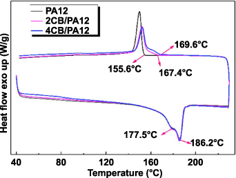
Figure 33. DSC curves of PA12, 2CB/PA12 and 4CB/PA12 powders. Reprinted from [130], Copyright (2019), with permission from Elsevier.
Download figure:
Standard image High-resolution imageMechanical properties of composite parts of PA12 and 4 wt.% CB obtained from SLS were compared with extrusion and injection moulding (Ex-IM) [133]. The 25% higher flexural, ∼10% higher strength, and 35% higher tensile modulus were obtained with SLS compared with the Ex-IM technique. However, the strength and modulus of composite parts were much lower with the SLS than the Ex-IM because the nano-scale CB particles were dispersed in the polymer matrix and higher porosity of the composites made by SLS. Figure 34 shows the agglomerated CB particles on the fractured surface of composite part fabricated by SLS. Alejandro et al [127] investigated the mixing consistency, thermal stability, and mechanical properties of CB/PA12 parts printed with different weight percentages of CB. The tensile and compressive strengths were improved obviously due to the crack growth being partly blocked by the filled CB particles. Mechanical properties were degraded with a CB concentration of higher than 3 wt% because the physical contacts between PA12 particles were hindered by too many CB particles, resulting in a low laser binding process in SLS.

Figure 34. Fracture surface of the SLS PA-4CB composite. The white and dark regions are the CB particles and the polymer matrix, respectively. Reprinted from [133], Copyright (2011), with permission from Elsevier.
Download figure:
Standard image High-resolution image4.4.5.2. Clay reinforced PA composite.
For the SLS of clay nanoparticle/PA6 composites, Kim and Creasy reported that the nanoparticles decrease the crystallization temperature and reduce the crystallization peak width [122]. It is concluded that the movements of melting polymer molecules are inhibited by the filler particles, which prevents the molecules from completing the crystallization process until the driving force is large enough. Prashant et al [134] found that mechanical properties of clay reinforced PA composite were reduced because clay particles hinder the polymerization process of SLS bent powder of PA2200 and nano-scale clay. Yan et al [128] modified the surface of CFs through oxidation and coated them with PA12 to prepare CF/PA composite powders used for SLS. It was found that polymer composite of CF/PA decreases the initial melting temperature, resulting in lower part bed temperature.
4.4.5.3. Nano particles-filled polymer composites.
The thermal properties of clay nanoparticle/PA6 composite were studied [122]. The interactions between nanoparticles and polymer chains increased the heat of crystallization and the values of melt of fusion. The crystallization temperature was decreased by 3 °C after adding the nanoparticles, narrowing the crystallization peak width. The SLS parts of carbon nanotube/polymer composites were used to fabricate electrically conductive parts with complex structures [135, 136]. The electrical conduction was improved due to the segregated microstructures induced by laser sintering, but the thermal conductivity was affected by the inevitable pores of SLS parts. In some conditions, the SLS parts show an apparent increase in the electrical conductivity, as shown in figure 35. Nano-Al2O3 particles were coated with PC by emulsion polymerization and added into PS to prepare the SLS composite [124]. Since the absorbance of laser energy and particle dispersion in the matrix were improved with the coated fillers, a fully dense part could be laser sintered.

Figure 35. Conductivities comparison of SLS composite and hot-compressed composite. Reprinted from [136], Copyright (2018), with permission from Elsevier.
Download figure:
Standard image High-resolution image5. Applications
5.1. Biomedical applications
5.1.1. Tissue engineering (TE) scaffolds.
Bone TE focuses on producing patient-specific bone substitutes to treat serious skeletal defects that cannot heal on their own [137]. Since bone is a highly anisotropic composite material, it is of great interest to provide a similar scaffold structure that can imitate the environment of the extra-cellular matrix. SLS has been applied for fabricating such TE scaffolds [87, 88, 138, 139]. PCL, a biodegradable polymer, has been widely fabricated as scaffolds for bone TE by SLS [87, 140–142]. Das et al have verified that SLS of PCL could fabricate PCL scaffolds with nearly full density (>95%) and comparable properties matching those made by injection or compression moulding [109, 140, 142]. Figure 36 shows the STL file and fabricated PCL scaffold by SLS, indicating that the fabricated scaffolds and designs matched well with each other [87]. The compressive strength and modulus values were similar to trabecular bone, which supports the in-growth of bone in the vivo model.
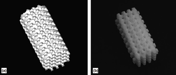
Figure 36. (a) STL image of a scaffold. (b) PCL scaffold prepared by SLS. Reprinted from [87], Copyright (2005), with permission from Elsevier.
Download figure:
Standard image High-resolution imageA porogen system has been combined with the SLS technology to fabricate biodegradable 3D scaffolds with a microporous structure for cell immobilization and a flow channel network to provide oxygen and nutrients for cultured cells by the Niino et al [143–148]. Biodegradable PCL was used as the SLS powder with the porogen sieved sodium chloride (NaCl) filler. A 3D scaffolds were fabricated by SLS, and a CO2 laser was used with a focal diameter of 550 μm. The salt particles were leached out from the SLS scaffolds by being immersed in flowing water for 2 h. Then, the scaffolds were ultrasonically cleaned for 10 h in flowing water. Figure 37 shows the CAD model of the scaffold, fabricated scaffold, and inner structures measured by x-ray and computer tomographies (CTs) method. Due to excessive sintering in the SLS process, the minimum channel diameter was reduced to 0.8 mm, which was 20% below the designed size. X-ray CT observation confirmed that the non-sintered powder was removed ideally, resulting in no clogged channel. The porogen dissolution process enhanced the removal of non-sintered powder. Human hepatoma Hep G2 cells were cultured on the scaffold for 9 d to evaluate their biocompatibility. The results show that the designed 3D flow channels are essential to the cell's growth and function [146].

Figure 37. (a) CAD model and (b) fabricated 3D scaffold. Reprinted from [146], Copyright (2007), with permission from Elsevier. (c) X-ray photo for a scaffold and (d) CT photo of cross sections. Reproduced with permission from [147].
Download figure:
Standard image High-resolution imageRecently, the mixed composite containing cuttlefish bone powders and poly(1-lactic acid) was made into scaffolds by SLS, and high resolution and good mechanical properties could be obtained [149]. Then, the scaffolds were partly converted to HA by hydrothermal method, and the conversion rate can be controlled by optimizing the parameters. Biphasic calcium phosphate (BCP), a boon substitute, is a mixture of HA and β-tricalcium phosphates. BCP scaffolds are very suitable for applications in bone TE due to their excellent physicochemical and biological properties. On the other hand, the SLS of BCP-based scaffolds often encounters many problems, such as the scaffolds deformation, component decomposition, and so on. Zeng et al used an indirect SLS strategy to fabricate BCP based scaffolds through two steps [150]. First, a relevant low temperature was used in the SLS process to fabricate the green part of the BCP scaffold in the presence of epoxy resin. In the second step, the epoxy resin was removed from the fabricated green part by a subsequent sintering process to obtain microporous BCP scaffolds. Diermann et al fabricated biodegradable poly(3-hydroxybutyrate-co-3-hydroxyvalerate) (PHBV) scaffolds by SLS without utilizing pre-designed internal pore architectures [151]. The porous microstructure of PHBV scaffolds was controlled by optimizing the SLS parameters, and it consisted of pores, islands, and bridges [152]. In vitro degradation of the PHBV scaffolds was investigated, and the results showed that a noticeable decrease in the average molecular weight (39%–46%) was observed compared with new scaffolds after incubating the scaffolds in PBS for 6 weeks [153]. Then, Akermanite (AKM) was filled into the PHBV matrix to fabricate PHBV/AKM composite scaffolds. The filled AKM particles exposed on the surface provided the excellent potential for cell attachment [154]. Since the AKM particles dispersed inside the scaffold skeleton, the mechanical properties of PHBV/AKM composite scaffolds were improved.
5.1.2. Foot and ankle-foot orthoses.
Ankle-foot orthosis (AFO) is one type of assistive device to enhance gait performance for patients. A traditional fabrication method of AFOs used craft techniques based on the plaster casting method, and a mould was to be prepared using the impression to fabricate an orthosis [155]. Recently, CAD and computer-aided manufacturing (CAM)-based methods have been applied to fabricate FOs [156]. Moreover, the SLS-based framework was verified to be feasible to manufacture AFOs customized for specific patients directly from the scanned image data [157]. Figure 38 shows the traditional and AM process to fabricate AFO [158]. One significant advantage of the SLS-based framework is that 'design freedom' is possible with few manufacturing constraints on geometry [159]. Then, Pallari et al also explored the potential of 3D scanning and the SLS method for a mass customization process and found that it was adequate to produce mass-customized orthoses using SLS [160]. The ankle kinematic and spatial-temporal gait parameters show no significant difference between the SLS-AFO and normal AFO manufactured by the traditional handcrafting method. The feasibility of using SLS to fabricate customized foot orthoses was studied, and the design freedom of the SLS-based method presented a range of opportunities that are not possible with current CAD/CAM-based systems.

Figure 38. Traditional and AM process to fabricate AFO. Reprinted from [158], Copyright (2016), with permission from Elsevier.
Download figure:
Standard image High-resolution image5.1.3. Implants and prostheses.
Custom-made implant fabrication, which does not need an anatomy model, is getting more and more attention [161]. Particular attention should be placed on the customization of the patient for cranial implant design. CT is used for cranial implant customization by accurately defining the implant contour and curvature to establish direct contact with bone tissue. The CT dataset can be directly used to produce a superior model for the SLS process [162–164], making the SLS a promising technology for custom-made implant fabrication. Figures 39(a)–(c) show the designed cranial implant and SLS PEEK cranial implant fabricated by SLS based on CT scanning of the patient's cranial defect. Equivalent results were observed when performing the mechanical characterization at a small area or the whole implant level, indicating that custom-made cranial fabricated by SLS has high accuracy. SLS has been used to manufacture a wax prototype for fabricating a partial nasal prosthesis [165]. Figures 39(d) and (e) show the wax model of the nasal prosthesis and resin model of nasal defect, which were fabricated by SLS. The completed partial nasal prosthesis on the patient shown in figure 39(f) was fabricated in a conventional manner [166]. The need for labour-intensive sculpting was significantly reduced using SLS because the nasal wax pattern was automatically manufactured based on the scanned CT dataset.

Figure 39. (a) Typical cranial implant, (b) designed cranial implant to be fabricated by SLS, and (c) SLS PEEK cranial implant ready for testing. Reprinted from [167], Copyright (2011), with permission from Elsevier. (d) Wax model of nasal prosthesis fabricated by SLS, (e) resin model of nasal defect fabricated by SLS, and (f) completed partial nasal prosthesis on the patient. Reprinted from [165], Copyright (2008), with permission from Elsevier.
Download figure:
Standard image High-resolution imageSurgical guides have been fabricated by SLS. A CT scan of the patient's dental arch was completed first, and the resulting CT image was converted into digital imaging [168–170]. STL file used in SLS was to be created from the CT image with the help of CAD/CAM software. Finally, the surgical guide was to be fabricated by SLS. Figures 40(a) and (c) show different types of surgical guides fabricated by SLS [168, 169]. Figure 40(a) shows the SLS prosthetic guide [168]. It was used to evaluate the accuracy and complications that arose from using SLS surgical guides for flapless dental implant placement and immediate definitive prosthesis installation, and figure 40(b) shows that surgical guide in position. The results showed that the deviations could not be avoided from the plan totally by using the surgical guide. Figure 40(c) shows an SLS surgical guide that includes alveolar mucosa architecture, which is different from the surgical guide shown in figure 40(a). The clinical performance of the SLS surgical guide was evaluated, and the ability of SLS for immediate interim prostheses showed huge advantages in clinical applications [169].

Figure 40. (a) SLS surgical guide and the maxilla and (b) surgical guide in a position. Reproduced with permission from [168]. (c) SLS prosthetic guide with alveolar mucosa architecture (d) fixed surgical guide. Reprinted from [169], Copyright (2016), with permission from Elsevier.
Download figure:
Standard image High-resolution image5.2. Pharmaceutical applications
With the development of AM technology, it is possible for the flexible manufacture of individual units with doses or other forms tailored to the patient (personalized medicine) [171]. SLS has gotten the least research for pharmaceutical industrial compared with other AM methods, such as FDM. However, SLS has many advantages for the manufacture of personalized medicines. Since pharmaceutical applications of the SLS method is relatively new, most of the reference papers have been reported in the past 20 years. SLS is mainly used to fabricate personalized medicines, such as medicines for rare diseases [172]. SLS enables better stability to drug substances because it is a solvent-free process. Different drug release rates and mechanical properties can be combined in one SLS tablet by controlling process parameters and material attributes [173, 174]. However, the most significant disadvantage of SLS in pharmaceutical applications is the effect on laser-sensitive substances, which limits the available materials and drugs for SLS [36]. Furthermore, large quantities of powder are required to maintain consistent layer height and powder flow, which might be suitable in some cases, such as expensive drugs. In addition, the chemical stability and physical changes of powders are also concerned for recycled powders [175]. More details about the SLS print sets can be found in two recent review paper by Charoo et al [172] and Awad et al [171]. This paper focuses on the SLS processes of different formulations.
Fina et al found that SLS is a suitable AM technology for preparing drug-loaded oral dosage forms using pharmaceutical grade excipients [176]. Paracetamol USP grade was used as a model drug, and Kollicoat IR and Eudragit L100-55 were used for instant release coatings. Moreover, 3% of Candurin® Gold Sheen was used as an absorbent excipient to be added to all the formulations. Figure 41(a) shows the SLS tablets with the compositions of (left) 77% Kollicoat IR and 20% paracetamol and (right) 77% Eudragit L100-55 and 20% Paracetamol, which were smooth and showed yellow colour. It demonstrated that SLS technology could be used for fabricating formulations with different drug loadings. Since the degradation of the drug due to high laser energy was the primary concern for the feasibility of SLS formulations, the drug concentrations in the SLS tablets were evaluated by HPLC (Hewlett Packard 1050 Series HPLC system). The measured drug concentrations were close to the theoretical drug loading. The HPLC chromatograms showed that the concerned drug degradation did not occur during SLS.

Figure 41. (a) SLS tablets with the compositions of (left) 77% Kollicoat IR and 20% paracetamol and (right) 77% Eudragit L100-55 and 20% Paracetamol. They contain the same composition of 3% Candurin® Gold Sheen. Reprinted from [176], Copyright (2017), with permission from Elsevier. (b) SLS fabricated gyroid lattice solid dosage forms. EUD L and EC formulations contain 92% Eudragit L100-55 and 92% Ethylcellulose N7. They contain the same compositions of 3% Candurin® Gold Sheen and 5% paracetamol. Reprinted from [177], Copyright (2018), with permission from Elsevier. (c) Dual SLS minitablets. The yellow regions mean the Ethyl Cellulose regions, whereas the blue regions mean the Kollicoat Instant release regions. Reproduced from [174]. CC BY 4.0.
Download figure:
Standard image High-resolution imageSelf-supporting gyroid lattice and bi-layer constructs tablets were fabricated by SLS to tailor the drug release behaviour [177]. Figure 41(b) shows the SLS printed gyroid lattice solid dosage forms of the different polymer formulations. The internal lattice density, cell size, geometry and dimensions of designed drug structures can be tailored by selecting appropriate SLS parameters. The drug dissolution characteristics showed that more fluids permeate into the polymer matrix to cause an accelerated dissolution effect by enhancing the polymer porosity and increasing the contact surface. SLS has been used to print two model drugs into one small dosage form with a diameter of 1 or 2 mm to achieve two different release profiles within one minitablet [174]. Figure 41(c) shows the dual SLS minitablets with the model drugs of Ethyl Cellulose and Kollicoat Instant. The dissolution profiles show that the two regions in figure 41(c) maintain distinct release properties. Moreover, the minitablets' drug release rate was increased by decreasing the tablet diameter because the surface area was increased due to the reduced diameter. The release properties of SLS dosage forms were also closed with the scanning speed of the laser. Figure 41 shows the dissolution profiles of SLS hydroxypropyl methylcellulose based formulations with different laser scanning speeds [178]. The drug release is faster with a higher laser scanning speed due to the looser particle concentrations and higher porosity of the SLS dosage forms.
5.3. Chemical applications
5.3.1. SLS porous catalysts.
For the SLS of porous catalysts, the catalytical component is attached to a printable polymer structure. Physical properties of the porous catalysts, such as porosity, were controlled by changing the SLS process parameters. Highly porous flow-through filters were made by SLS with the mixed powder containing 10 wt% of commercial MOF copper (II) benzene-1,3,5-tricarboxylate (HKUST-1) and N12 powder [179]. Figure 42 shows the SLS MOF/N12 filter disks after different treatments. Since the added MOF is attached to the partially fused N12 surface, fluids can access the MOF after passing through the filter. Moreover, powder x-ray analysis confirmed that the laser did not negatively impact the MOF structure, and MOF activity was not affected according to the CO2-adsorption studies. In the case of SLS porous hydrogenation catalysts, Pd/SiO2 powder and PP were mixed to be used for SLS [180].

Figure 42. SLS MOF/N12 filter disks after different treatments. (a) The left one was placed in the oven, and the right one was in ambient air. (b) The same disks in (a) were explored in the air for 5 min. (c) The filter disk was removed from the oven with a droplet of water. [179] John Wiley & Sons. © 2019 Wiley-VCH Verlag GmbH & Co. KGaA, Weinheim.
Download figure:
Standard image High-resolution imageMoreover, the SLS process does not significantly impact the catalytic performance of the catalytically active component. When the SLS porous catalysts were used for Suzuki-Miyaura cross-coupling reactions, they showed similar performance to the pristine powdery commercial catalysts [181]. There was almost no change the SLS porous structure on the outer and inner surfaces of the porous catalysts after ten reaction cycles. It was only found that some loosely attached un-melt particles were lost, which demonstrates that the SLS porous catalysts have high mechanical durability under the reaction conditions.
5.3.2. SLS porous filters.
The 3D porous filter has been fabricated by SLS with N12 to recover gold directly from the printed circuit board [182]. Figure 43 shows the single SLS filter and complete gold filter system consisting of three parts: funnel, filter, and reservoir. Gold can be selectively captured in the filter system, and the excellent selectivity of nylon might be the [AuCl4 −]. Then, a mixture of PP with 10 wt% of type-a anion exchange resin was used as SLS powder to fabricate a high porous filter to recover Pd and Pt [183]. The chemically active resin (10 wt%) is responsible for the recovery function, and the PP is used as the matrix for the active component. SLS process parameters were adjusted to control the porosities and the geometrical properties of the filters. The filters are reusable without significant loss of their ion-capturing performance. The mixture of chitosan and thermoplastic polyurethane was made into a membrane by SLS [184]. The membrane could absorb heavy metal ions Cu(Ⅱ) and Pb(Ⅱ), and the membrane could also adsorb palladium ions to form palladium-loaded composite materials.

Figure 43. (a) SLS N12 filter. (b) A flow restricting funnel was on the filter unit. (c) The assembled filter system. Reprinted with permission from [182]. Copyright (2017) American Chemical Society. https://pubs.acs.org/doi/10.1021/acsomega.7b01215. Future permissions related to the material excerpted should be directed to the ACS.
Download figure:
Standard image High-resolution image5.4. Electronic applications
Laser direct structuring (LDS) process has been realized on SLS parts by the LPKF Laser & Electronics AG in Garbsen, Germany. LDS is a process in which the circuit pattern is fabricated on moulded thermoplastics through laser patterning and electroless plating. The combination of SLS and LDS is promising to improve the development of moulded interconnect devices (MIDs), produced mainly by injection moulding and LDS, in terms of their 3D geometry, and manufacturing process and functionality. Figure 44 shows the schematic process of MID fabrication [185]. The mechanism of LDS is using an Nd:YAG laser (λ = 1064 nm) to induce activation of a mixed thermoplastic polymer and a particular additive, and the specific additive is dispersed in the thermoplastic polymer a chemically passivated state. The additive can be locally cleaved by the Nd:YAG laser selectively on the component's surface, resulting in catalytically active metal seeds arising on the surface. Since SLS can fabricate components with more complexity than injection moulding, SLS has a great potential to improve the component complexity of MIDs instead of the conventional injection moulding method [186] However, there is still an agent requirement for the commercial powder materials, which fulfils requirements for SLS fabrication, LDS structuring, and metallization [187].
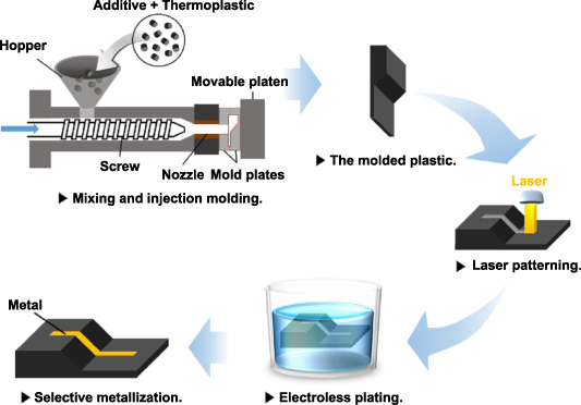
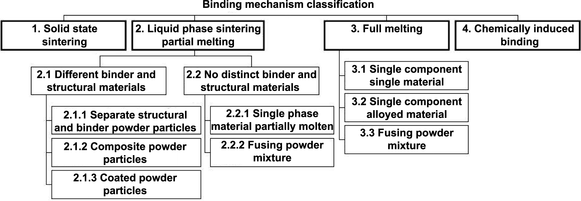
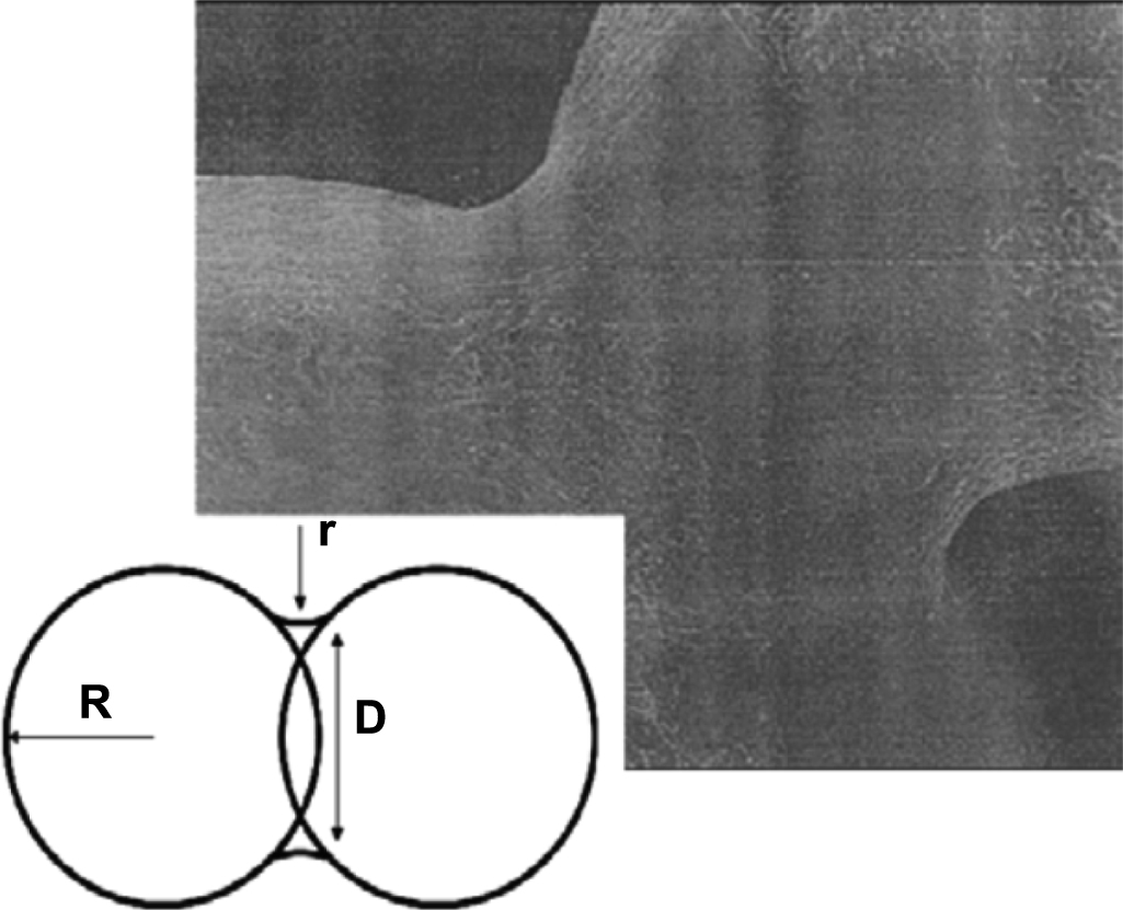
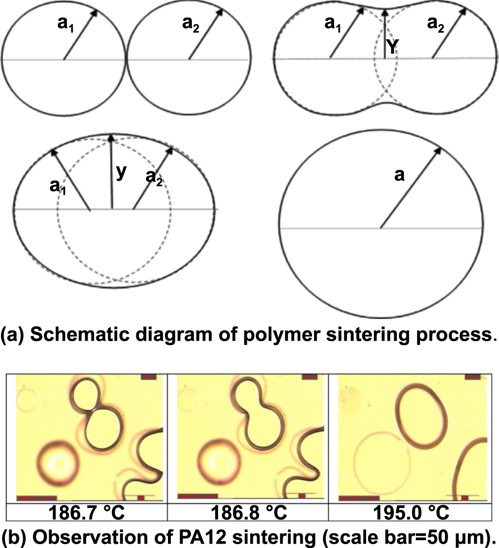
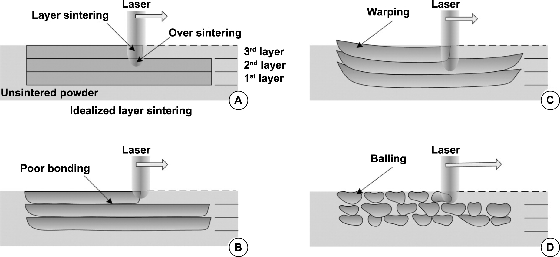
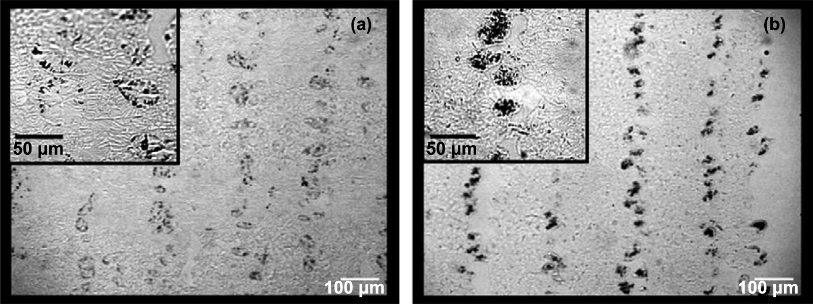
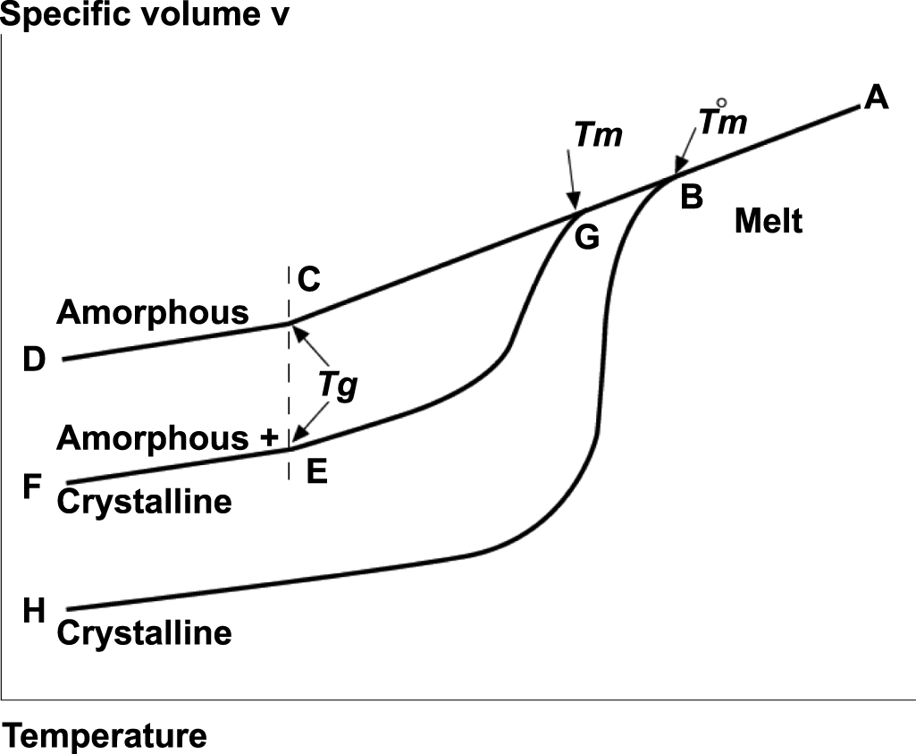
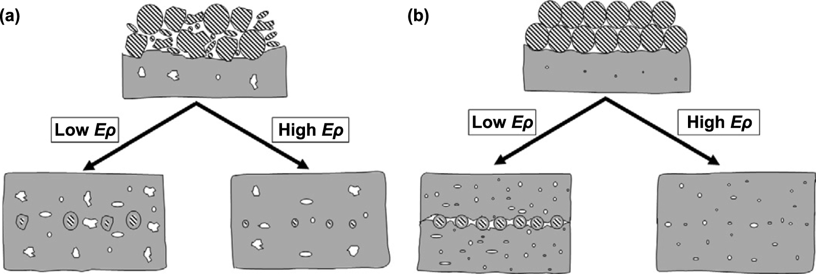
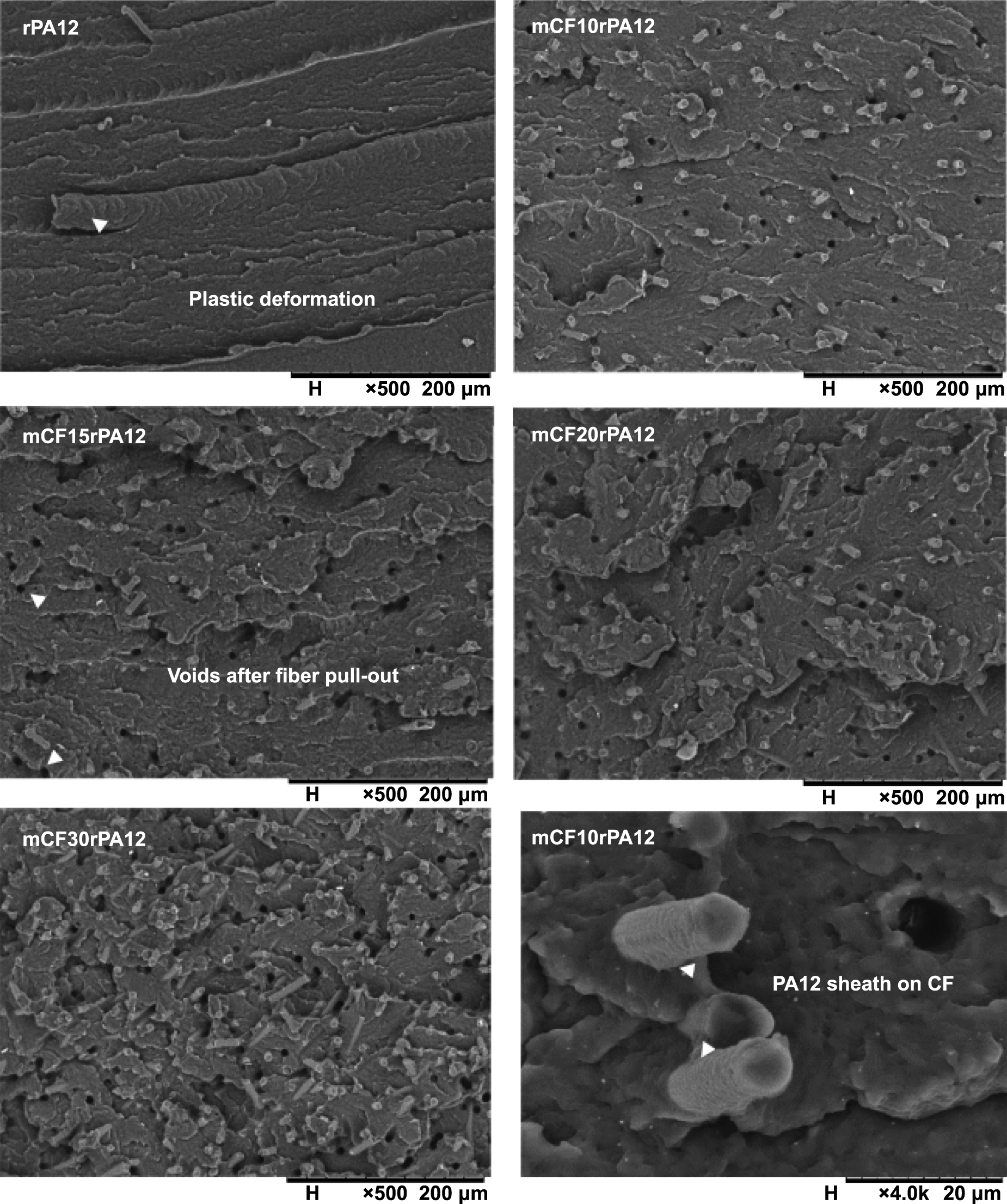
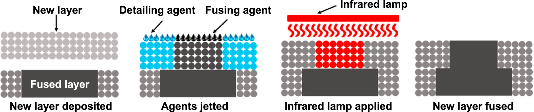
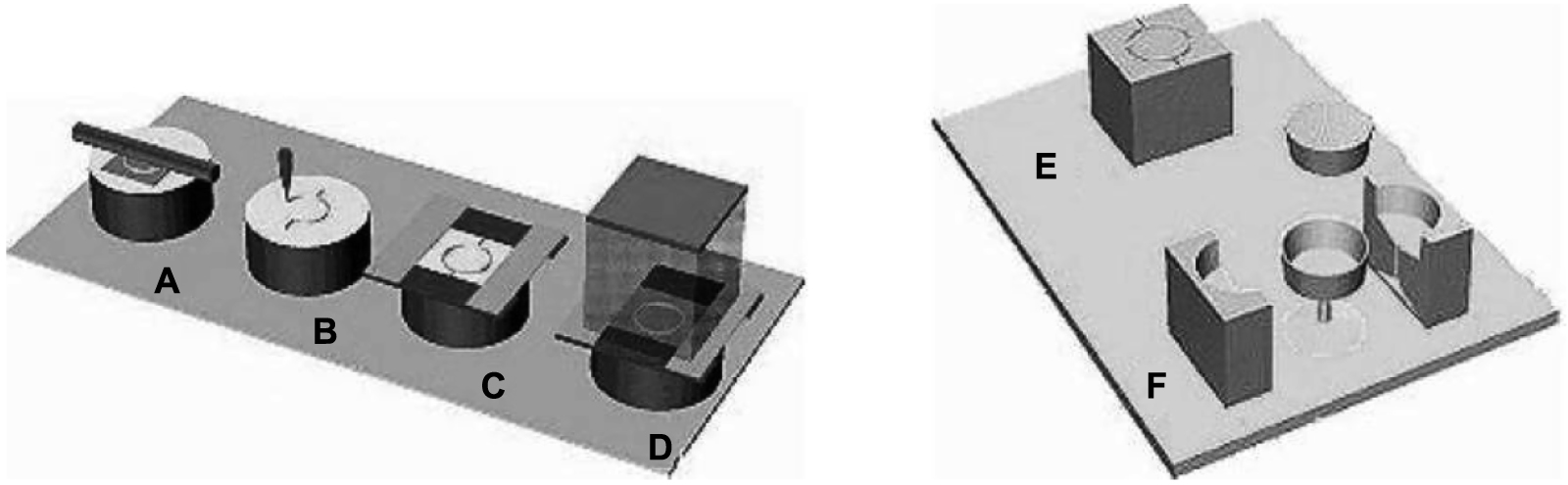
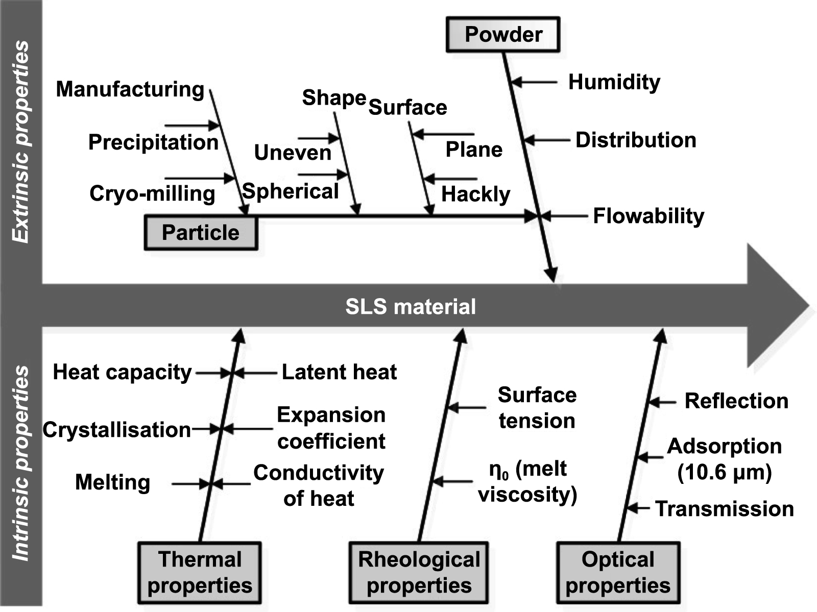
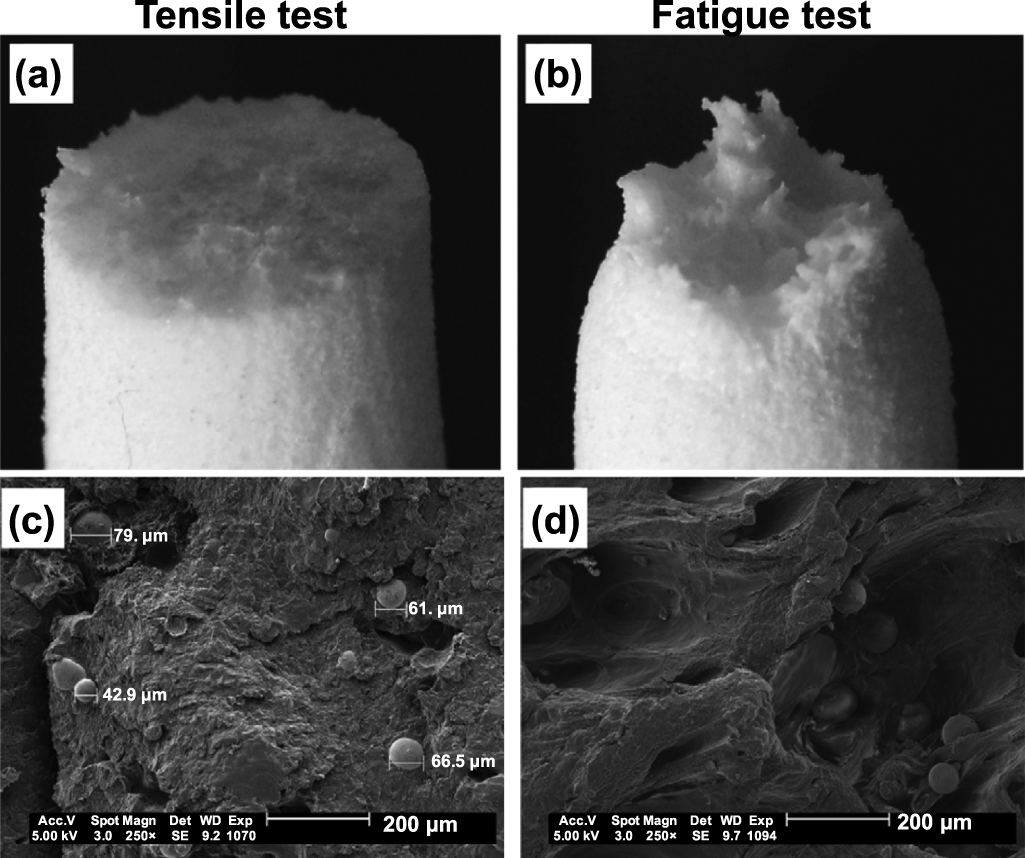
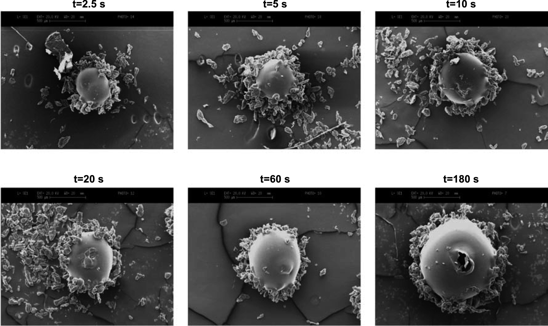
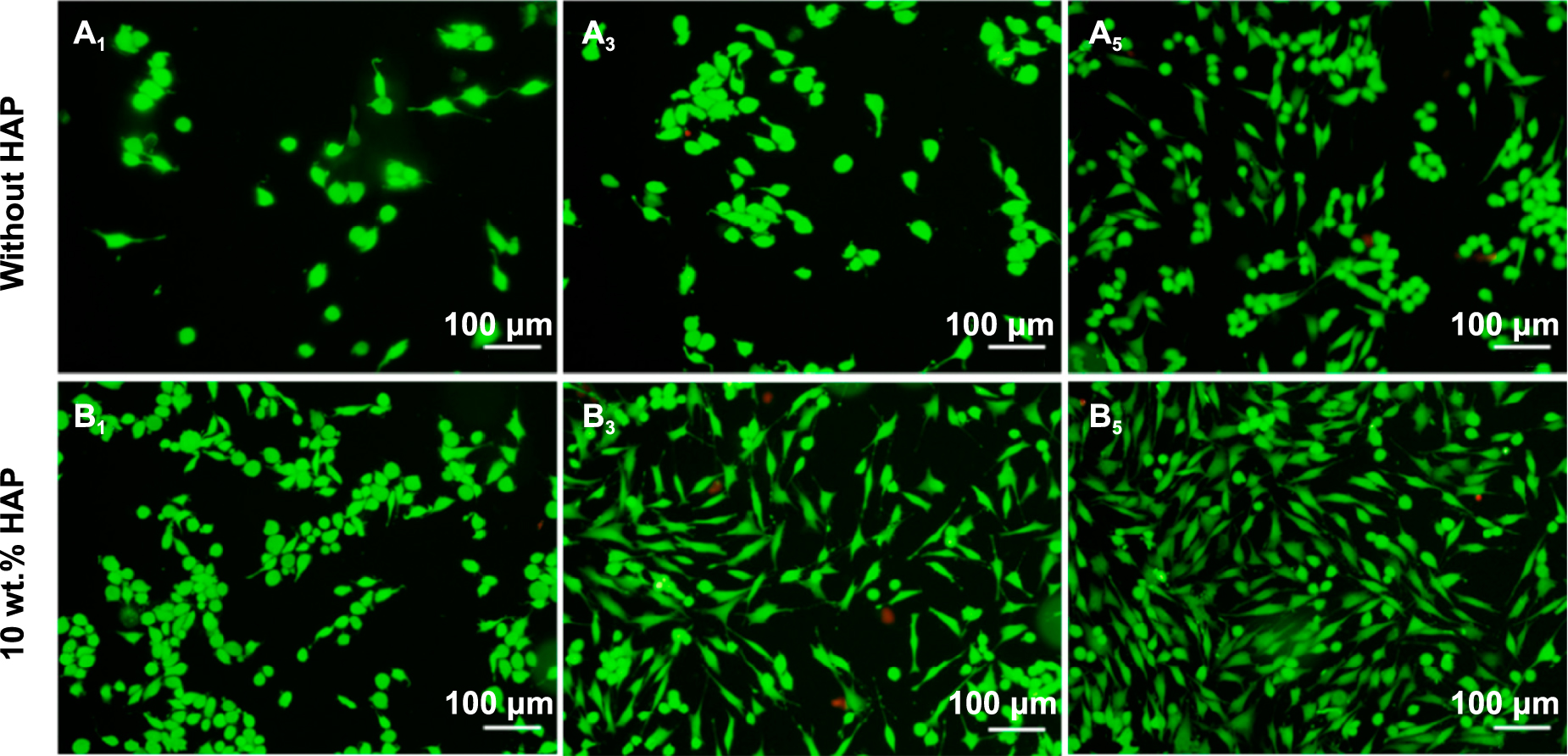
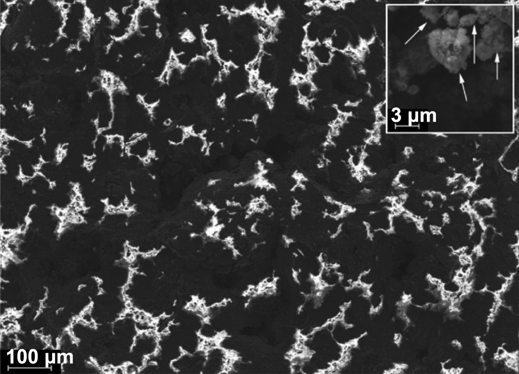
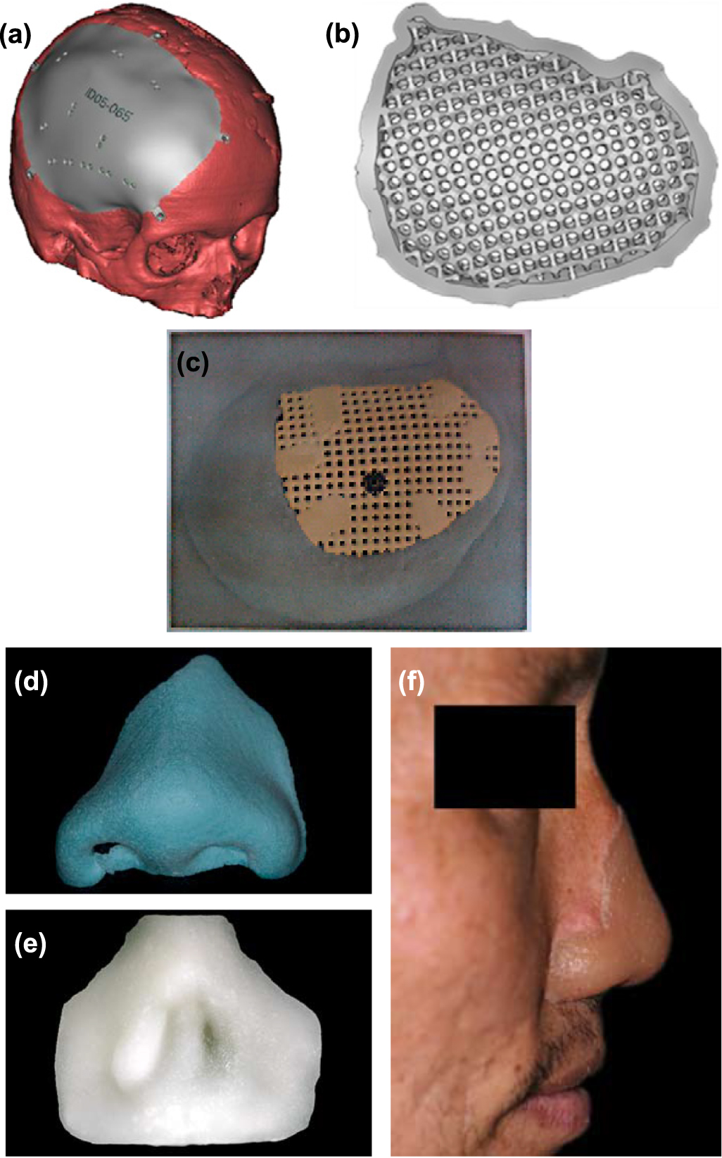
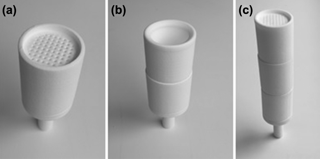
Figure 44. Schematic process of MID fabrication. Reprinted from [185], Copyright (2017), with permission from Elsevier.
Download figure:
Standard image High-resolution image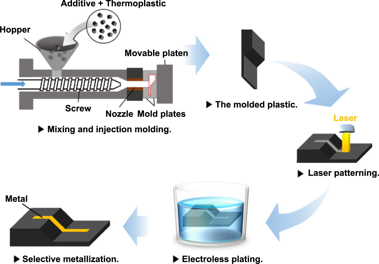
Niino et al has tried to sinter commercial LDS compatible PA10T based material, VESTAMID HTplus LDS3031 black (Daicel-Evonik), by SLS using CO2 laser to achieve a relative density of 68% [186]. Then, the area irradiated by fibre or CO2 laser was successfully metalized by non-galvanic plating, and the un-irradiated area was not metalized. This indicated that the previous SLS process did not affect the activation properties of the LDS compatible material. The SLS process was extended to fabricate circuit components in both metal and dielectric layers, such as capacitors and inductors [188, 189]. It was demonstrated that SLS is capable of fabricating metal–insulator–metal capacitors. A comparison between fused deposition modelling and SLS were conducted in manufacturing lightweight structure for the drone with intricate thin features, and SLS was superior in this aspect [190].
6. Challenges and perspectives
This paper reviews the rapid development in SLS polymers from particles coalescence mechanism, suitable SLS materials, and practical applications. Although the SLS method has been proposed since the mid-1980s and has received long-term attention and research, there are still many challenges in the fundamental mechanisms and industrial applications.
- (a)The fundamental particle coalescence mechanisms are still unclear due to the complex polymer molecular structures and diverse laser sintering modes. The particles coalescence mechanism becomes more complicated when many polymer-based composites are used in SLS to achieve better properties of SLS parts than those with a conventional single polymer.
- (b)The available types of SLS polymer are limited, which hinders the wide industrial applications, especially when SLS parts are to be used in the fields of biomedical, pharmaceutical, and chemical applications. The industry is of great interest in developing new SLS materials, including the new powder production methods.
- (c)The low printing speed of SLS still significantly limits the industrial applications of SLS parts, although some high speed sintering methods, such as MJF and SIS, have been developed. The heating and cooling process takes a too long time before and after SLS. The printing speed should be increased further by developing novel high speed sintering methods or suitable polymer materials.
- (d)The surface roughness of SLS parts is high due to the powder size. The SLS parameters can be optimized to reduce the surface roughness; however, it is difficult to get a sufficiently low value. Therefore, the post treatment of the SLS surface is necessary, and it is difficult to polish some micro-structure surfaces and complex 3D structures without changing their structural accuracy.
- (e)SLS polymer simulation is a complex multi-disciplinary process, and there are very few research reports on the numerical simulation of SLS polymers. The challenges in the SLS polymer simulation need more study to predict the defects, such as porous structure and warping.
Acknowledgments
The authors would like to thank the support from the Shanghai Science and Technology Committee Innovation Grant (Grant No. 19ZR1404600) and Fudan University-CIOMP Joint Fund (FC2020-006).