


Abstract
Peripheral light harvesting complex (LH2), which is found in photosynthetic antenna systems of purple photosynthetic bacteria, has important functions in the photosynthetic process, such as harvesting sunlight and transferring its energy to the photosynthetic reaction center. The key component in excitation energy transfer (EET) between LH2s is B850, which is a characteristic ring-shaped aggregate of pigments usually formed by 18 or 16 bacteriochlorophylls in LH2. We theoretically study the strategy of the ring-shaped aggregate structure, which maximizes EET efficiency, by using the standard Frenkel exciton model and the self-consistent calculation method for the Markovian quantum master equation and Maxwell equation. As a result, we have revealed a simple but ingenious strategy of the ring-shaped aggregate structure. The combination of three key properties of the ring unit system maximizes the EET efficiency, namely the large dipole moment of aggregates causes the basic improvement of EET efficiency, and the isotropic nature and the large occupying area are critically effective to remove the disorder-induced shielding that inhibits EET in the presence of the randomness of orientation and alignment of carriers of excitation energy.
Export citation and abstract BibTeX RIS

Content from this work may be used under the terms of the Creative Commons Attribution 3.0 licence. Any further distribution of this work must maintain attribution to the author(s) and the title of the work, journal citation and DOI.
GENERAL SCIENTIFIC SUMMARY Introduction and background. Behind the geometrical structures obtained through the long history of biological evolution, ingenious strategies are often hidden. Peripheral light harvesting complex (LH2), which is found in the photosynthetic antenna systems of purple photosynthetic bacteria, has a characteristic ring-shaped structure. Some researchers believe that this geometrical feature plays an important role in realizing the surprisingly high efficiency of transfer of the harvested photon energy to the photosynthetic reaction center (RC), to which many studies have been devoted for a long time.
Main results. By using a simple model of the ring-shaped aggregate, this paper elucidates that a simple but ingenious strategy behind three geometric properties of the ring-shaped aggregate overcomes the shield against the energy transfer, 'disorder-induced shielding', due to the biological disorders of position and orientation of pigments, realizing a highly efficient energy transfer. The large dipole moment of aggregates causes the basic improvement of the energy transfer efficiency, and the isotropic nature and the large occupying area of the ringed aggregate are critically effective in removing the disorder-induced shielding that inhibits the energy transfer.
Wider implications. This result indicates a typical example that a combination (or integration) of simple geometrical properties of the unit structure leads to an anomalous biological function of the entire system. This finding is thought-provoking and will encourage further debate on the mechanism of the energy transfer in photosynthetic antenna systems. Also, this would provide a guiding principle for engineering applications leading to artificial nano-systems for future energy technologies.
1. Introduction
In photosynthetic antenna systems of purple photosynthetic bacteria, peripheral light-harvesting complex (LH2) [1] surrounds LH1-reaction center (RC) core complexes, where RC is located at the center of the core light-harvesting complex (LH1) [2]. The energy of sunlight absorbed by an LH2 is transferred to other LH2s, to LH1, and finally to the RC. The Qy transitions of bacteriochlorophylls (BChls) of B850, which is a ring-shaped pigment aggregate usually formed by 18 or 16 BChls in LH2, are responsible for the majority of inter-LH2 excitation energy transfer (EET) and also for absorbing sunlight, together with other pigments in LH2 [2–4] (figures 1(a) and (b)). The B850 ring generates 18 or 16 excitonic states to absorb the wide range of energy; the lowest and highest states are non-degenerate, and all the other states are doubly degenerate. The second lowest states are optically allowed, whereas all the other states are optically forbidden (figure 1(c)). Although the excitonic wave function would spread over the entire ring in the ideal case, it may, in reality, be limited by both static and dynamic disorder [5–9]. EET in photosynthetic antenna systems has been intensively studied by many researchers for years. Some theoretical investigations are made by applying the generalized Förster theory, which provided important insight into the EET rate from another aggregate of BChls in LH2 called B800 to B850 [4, 10, 11], and EET in a wider range of antenna systems involving more than two B850 rings [12–14]. Although the coherent energy transfer between donor and acceptor aggregates is overlooked in the generalized Förster theory, more precise calculations covering this point are recently developed and providing new understanding about EET in photosynthetic antenna systems [15–18]. On the other hand, the polaron model, which is typically used for the description of spectroscopy or localization dynamics within a ring [6–8], may provide another picture of inter-ring EET. Although a great deal of knowledge on EET in photosynthetic antenna systems has been obtained, as evidenced in the discussion above, a variety of scenarios are still open to understand EET.

Figure 1. (a) B850 (upper ring), B800 (lower ring) and protein (ribbons) in Rhodopseudomonas acidophila (Rps. acidophila) drawn referencing PDB:2FKW [19] with visual molecular dynamics (VMD) [20]. Nine carotenoid molecules also exist, but are not shown. (b) Schematic of B850. Eighteen lines denote the positions and orientations of Qy transitions of BChls. In calculations, the positions of point dipoles are set to the center of 18 lines to form a true circle with the common nearest-neighbor distance 9.38 Å and the orientations are slightly tilted (20°) from the tangential line of the ring. All positions and orientations exist on one plane. (c) Doubly degenerate second-lowest exciton states. Small arrows represent the relative magnitude and orientation of transition dipoles in this state, and the large arrow represents the imaginary dipole as the total polarization of a ring. As it is degenerate, this state has the freedom of rotation in the plane.
Download figure:
Standard image High-resolution imageIn this paper, we focus on some characteristics of EET originating from the fundamental geometrical structure of EET carriers. This study might shed light on the results of existing studies from the viewpoint of their relation to the merits of geometrical structures, and it will encourage further debate on EET in photosynthetic antenna systems and the motivation to realize artificial EET nano-systems.
2. Model of ring-unit and single-unit systems
Generally, the long-range ordering of carriers based on a certain rule is highly effective to maximize EET efficiency [21], while such ordering is usually difficult to realize in bio-systems and a different strategy is necessary to overcome inevitable fluctuations or randomness. By the complementary combination of the basic physical properties of constituent carriers, photosynthetic systems realize highly efficient EET overcoming the problem of randomness, which is simply owed to the ring-shaped structure of carriers as figured out below. In the early study of the geometrical effect of carriers by Fetisova and Borisov [22], the issue of how the lattice structure of carriers and their orientations are optimized for the efficient EET was theoretically investigated by the model system of the carrier's lattice. Recently, such studies have been made for experimentally observed arrangements of carriers of various kinds of bacteria and for some different conditions of incident light [23, 24]. On the other hand, the functional role of the characteristic ring shape of LH2 has been attracting research recently and some theoretical studies were performed for the model systems including several rings [25, 26]. In our recent study, we compared two types of physical model systems: the ring-unit system (figure 2(a)) and the single-unit system (figure 2(b)), in order to clarify the advantage of the characteristic ring shape of B850 in EET for the model including a large number of units, and found a greatly higher efficiency of EET for the former in the case of a certain number of pigments [27]. Although we have pointed out some properties of the ring-unit system for this advantage as summarized later, the main question, why the ring shape has a great advantage for EET, has not been answered yet. Here, we elucidate the underlying mechanism for the advantage of the ring shape. In the following demonstrations, the ring-unit system is an assembly of ring-shaped aggregates consisting of 18 pigments that models B850 rings, whereas the single-unit system is composed of simply scattered single pigments with uniaxial transition dipole moment fixed in a plane, and it embodies the simplest strategy for carrying energy quanta. Note that the single pigment has geometrically anisotropic nature. The positions and orientations of B850 rings in the ring-unit system are determined by a random number generator under the restriction that the distance between any two centers of B850 rings must be longer than 78 Å. This is reported to be the distance in artificial LH2 crystals [28], namely the diameter of the occupying area of LH2. The positions and orientations of single dipoles in the single-unit system are determined in the same way, but with the restriction that the distance between two pigments must be longer than 9.38 Å, which corresponds to the distance of the nearest-neighbor BChls in B850 rings. The information about these two types of systems is summarized in table 1 together with other physical model systems, which will be introduced later.
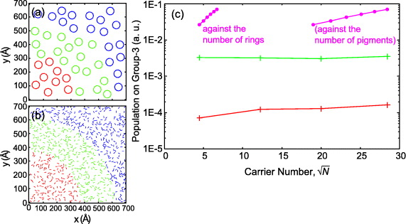
Figure 2. (a) The ring-unit system. A ring is modeled as an aggregate consisting of 18 pigments as shown in figure 1(b). (b) The single-unit system or single-unit-21 Debye system. (c) Group-3 population of the ring-unit system (pink) plotted against the number of rings (against the number of pigments). Group-3 population of the single-unit system (red) and single-unit-21 Debye system (green). The points are N = 20 (360), 25 (450), 30 (540), 35 (630), 40 (720) and 45 (810) for the ring-unit system and N = 20, 150, 400 and 810 for the single-unit system and single-unit-21 Debye system.
Download figure:
Standard image High-resolution imageTable 1. The summary of physical characters of all types of systems. A ring is counted as a carrier in the ring-unit system.
| Ring-unit system | Single-unit system | Single-unit-21 Debye system | Iso-dipole system | |||
|---|---|---|---|---|---|---|
| 1 | 2 | 3 | ||||
| Dipole moment of carriers (Debye) | 21 | 7.1 | 21 | 21 | 21 | 21 |
| Minimum distance (Å) | 78 | 9.38 | 9.38 | 9.38 | 27.4 | 78 |
| Isotropy of carrier | Isotropic | Anisotropic | Anisotropic | Isotropic | Isotropic | Isotropic |
3. Theoretical method for evaluation of excitation energy transfer efficiency
We divide rings or pigments in the systems into three groups—group-1 to group-3—based on the distance from the origin (see appendix A for details); after only group-1 is exposed to a Gaussian light pulse, we observe the population distribution at the time determined by the inverse of the dephasing constant of pigments (τd ≃ 400 and 4 ps are assumed), namely we see EET before reaching the stationary state. The shorter dephasing time, τd ≃ 400 fs, is for the B850 ring in the physiological situation. Since the essential effects are qualitatively identical for both depahsing constants as shown in appendix E, we see the result for τd ≃ 4 ps, in the main text, for more visible demonstration.
The theoretical calculation in this study is based on the standard Frenkel exciton model. For the systems of anisotropic dipoles (the ring-unit system and single-unit system), the Hamiltonian of each system consists of the following parts:


where  , ℏωλ and
  represent, respectively, the annihilation operator of excitation at pigment λ, the site energy of pigment λ and the ith phonon mode with its energy ℏΩi interacting with site λ through the coupling constant
  . We should note the following relations:


The second term in the rhs of equation (1) represents energy transfer between different sites. ℏgλ1λ2 is the transfer energy due to dipole–dipole interaction whose explicit expression is dλ·dλ'/r3λλ' − (eλ'λ·dλ)(eλλ'·dλ')/r3λλ', where dλ is the dipole moment of the λth pigment and we define rλλ' = |rλ − rλ'| and eλλ' = (rλ − rλ')/|rλ − rλ'| with the position vector rλ of the λth pigment. The third term represents the interaction between exciton and transverse electric field ET(r,ω) of light.  denotes the transition dipole moment operator. In this study, we assume the point transition dipole moment of Qy transition of each λth pigment:

where dλ and eλ represent the magnitude of the transition dipole moment and unit vector, respectively.  causes the dephasing on each pigment λ and the effect is included in the relaxation term in the Markovian quantum master equation which will be introduced below. The effect of coupling with the environment is considered by introducing the pure dephasing alone because the population lifetime (several hundreds of ps to 1 ns) [29] is much longer than the time scale of EET between B850 rings (several ps), which interests us here. Now, we employ the following Markovian quantum master equation derived from the above Hamiltonians:


The relaxation term  causes the dephasing at each pigment, which is the simplest way of treating pigment–phonon interaction. However, it provides a sufficient description of the incident EET dynamics after the photoexcitation of pigments and before reaching the stationary state, because the effects of the complicated damping mechanism arising from the fact that pigments forming the complex system appear on a longer time scale than that for respective pigments [30]. From these equations, we obtain the differential equations within the linear response to determine the variables
  ,
,  and
and  . By considering a self-consistent coupling between these equations and the Maxwell equation [31], the population
  can be obtained. In the actual calculation, to save numerical computation time, we neglect contributions of the quantum correlation between the different sites
 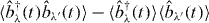 that are not essential for the present study. (The detailed calculation procedure to obtain the population is given in appendix B.) In an antenna system, high EET efficiency is required rather than a tendency to hold energy after absorbing sunlight. Thus, we use the population in group-3 after the dephasing time as the measure of EET efficiency. In our demonstration, we limit ourselves to the linear response regime, and thus population distribution means the probability distribution of excitation by a single photon. The total population in each system is normalized to unity (see appendix C for the figures of population distribution in the systems). The unit carrier of EET can be considered to be a pigment in the single-unit system, whereas a ring can be considered as the unit carrier in the ring-unit systems. (Note that the unit of excitation is still the respective pigment even for the ring-unit system.)
Before showing the results, here, we mention the limitations and advantages of the present method. Since this method treats the pigment–phonon interaction in a simple way, it is difficult to demonstrate EET including the incoherent energy transfer on a long time scale, which can be carried out by some existing methods, for example, Ishizaki and Fleming [17], where they treat excitonic dynamics and Förster mechanisms in a unified manner by calculating the interaction among all pigments and the interaction between pigments and phonons in a non-perturbative manner. On the other hand, our method is appropriate to study the characteristics of EET especially arising from the geometrical structure of pigment aggregates as the EET carriers in the system composed of a large number of aggregates. In our study, we focus on the non-equilibrium energy transfer just after photoexcitation and before reaching the stationary state. Thus, only considering the pure dephasing for each pigment is sufficient as explained before. This simplification enables us to greatly reduce the computational load and calculate the population dynamics including the interaction among all pigments in a non-perturbative manner without distinguishing donor and acceptor. Here, it should be noted that by using the present method, we properly take into account the delocalization of excitons among different pigments and the contribution of dark exciton states of rings in EET for both models, the ring-unit system and the single-unit system, because our model includes the dipole–dipole interaction between the pigments for all their combinations in the entire system. We explicitly show how the dark states contribute to our calculation in appendix D.
4. Results
First, let us consider the single-unit system. In this system, the most primitive strategy for enhancing EET would seem to be simply increasing the number of pigments. However, the result in figure 2(c), where we plot the group-3 population over a range of carrier (pigment) numbers after sufficient averaging for different realizations of carrier distribution (see appendix F for statistics of data points), shows that only increasing the number of pigments is not effective to reach fully efficient EET, which is clear if we look at the result for the ring-unit system. This is due to the 'disorder-induced shielding' that we will discuss in detail below. As compared with the single-unit system, the result of the ring-unit system, shown in figure 2(c), presents two surprising aspects. Firstly, the EET efficiency of the ring-unit system is a couple of hundred times larger than that of the single-unit system when the total number of pigments in the simulation area is 810. Secondly, the growth rate of EET efficiency in the ring-unit system is much higher than that in the single-unit system. (Note that the vertical scale is logarithmic.)
In the above demonstrations, we employ the longer dephasing time τd ≃ 4 ps, and also we neglect the energetically static disorder. It is interesting to see how the larger dephasing and energetically static disorder affect the above demonstrated tendency because these effects have a significant role in actual biological environments. We show the calculated results for the shorter dephasing time τd ≃ 400 fs in appendix E, and in the presence of the energetically static disorder in appendix D. As seen in these results, both effects weaken the difference between the two models, the single-unit system and the ring-unit system. However, we can find that a remarkable difference in EET efficiency between the two models still remains, which inspires us to explore the underlying mechanism for the advantage of the 'ring-shaped unit'.
5. Discussion
Before we proceed with the discussions, let us summarize the key properties of B850 rings in the comparison between B850 rings and pigments as carriers of EET [27].
1. The large dipole moment. Once the ring is excited, the dominant part of EET occurs through the second lowest state with the large dipole moment (figure 1(c)) among all the excited states of a ring. (See appendix D for the contributions of other states of excitons to EET.) The dipole moment of this state, 21 Debye, estimated from investigating the coupling strength of two rings is about three times as large as that of a single pigment, 7.1 Debye.
2. Isotropic nature. The dipole moment of the second lowest excitonic state has two degrees of freedom in the plane where it lies and hence has isotropic nature. Namely, the dipole moment faces any direction in a plane.
3. The large occupying area. The ring unit occupies a much larger area than a single pigment does.
We start from the general question of what properties should be added to realize higher EET efficiency with the simplest carrier, namely a pigment in the single-unit system, and we see if we can move from there to the ring-unit system. As we have already seen, only increasing the number of pigments is not an effective way to enhance EET. As we consider the next strategy, it seems natural to add the property of the large dipole moment, which is the first property of B850 rings, to the carriers. Thus, we change the dipole moment of single pigments in the single-unit system to 21 debye, which is the estimated dipole moment of an entire B850 ring. We call this imaginary system the single-unit-21debye system (figure 2(b), table 1). The EET efficiency is plotted in figure 2(c). As expected, the results clearly show that enlarging the dipole moment of carriers is an effective way to enhance EET efficiency. Nonetheless, the EET efficiency is still not high enough to match that of the ring-unit system. What suppresses EET here? Let us discuss the causes of these unexpected results. The force that suppresses EET originates from (i) the randomness of orientations and (ii) the randomness of positions of carriers. The randomness of orientation, in concert with the anisotropic nature of carriers, introduces pairs of dipoles whose relative orientations prohibit the transfer of excitation energy. The randomness of positions allows clusters and vacant areas to occur in the system, and these vacant areas suppress the spread of excitation energy. These are the origins of disorder-induced shielding that we introduced before. Let us now consider how nature beats this disorder-induced shielding.
The simplest way to remove disorder-induced shielding that results from the randomness of orientation is to change anisotropic carriers to isotropic carriers; isotropic nature is the second property of the B850 ring. For demonstration, we employ another imaginary system, changing the anisotropic carriers in the single-unit 21 Debye system to isotropic carriers (figure 3(a), table 1); we call this the iso-dipole system 1. (For a detailed excitonic model of this system, see appendix B.) The result of this system is shown in figure 3(d) along with results of the single-unit 21 Debye system. As expected, the EET efficiency of the single-unit 21 Debye system increases after adding the isotropic nature. However, we expect that disorder-induced shielding due to the randomness of positions is still suppressing the EET in iso-dipole system 1. Then, how can we remove the rest of disorder-induced shielding? There is some difficulty involved because the randomness of positions is a precondition in our model. However, the last property of the B850 ring, the large occupying area, shows us how to overcome this difficulty. We employ two other imaginary systems by enlarging the occupying area of carriers in the iso-dipole system 1: the distance between any two carriers is restricted to length greater than 27.4 Å in the iso-dipole system 2 (figure 3(b), table 1) and greater than 78 Å in the iso-dipole system 3 (figure 3(c), table 1). The results are given in figure 3(d), which shows that growth rates of EET efficiency are greatly enhanced by forming larger occupying areas of the carriers. This effect can be explained as follows: even though the system allows randomness in distribution of unit carriers, with the increase in carrier density it spontaneously approaches the close packing structure (figure 4(a)), which has no disorder-induced shielding because of the regular alignment. However, more carriers are needed in the systems with carriers of small occupying area in order to approach the close packing structure, and this reduces the growth rate of EET efficiency (figure 4(a)). To check the validity of our hypothesis, we show the EET efficiency in a regular lattice distribution of carriers of iso-dipole system 2 and iso-dipole system 3 in figure 4(b). We can see that the data points of the iso-dipole systems are consistent with those of the lattice distribution. From the above results, we understand that, if the occupying area of a unit carrier is small, many more carriers are needed to achieve the same EET efficiency than for the units with large occupying area. Thus, the occupying area of a unit carrier is important to realize efficient EET while making the most of a limited resource (limited number of pigments) in an in vivo system.
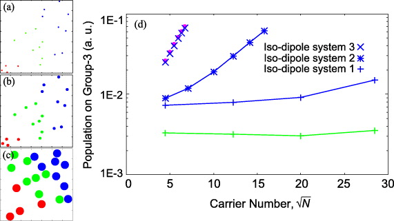
Figure 3. (a) Iso-dipole system 1, (b) iso-dipole system 2 and (c) iso-dipole system 3. The sizes of circles correspond to the three types of iso-dipole systems. (d) The group-3 population of the iso-dipole systems (blue), single-unit 21 Debye system (green), and ring-unit system (pink). N = 20, 150, 400, 810 for iso-dipole system 1, N = 20, 50, 100, 150, 200, 250 for iso-dipole system 2 and N = 20, 25, 30, 35, 40, 45 for iso-dipole system 3.
Download figure:
Standard image High-resolution image
Figure 4. (a) Structures of iso-dipole system 3 and lattice structures formed by carriers of iso-dipole system 3 (upper line), and structures of iso-dipole system 2 and lattice structures formed by carriers of iso-dipole system 2 (lower line). Many more carriers are needed to approach the lattice structure for iso-dipole system 2 compared with iso-dipole system 3. (b) The group-3 population in the iso-dipole systems and the two types of lattice structures in figure 4(a). The points of iso-dipole systems 2 and 3 are approaching their lattice points.
Download figure:
Standard image High-resolution image6. Conclusion
Having started from the single-unit system, we now come to the EET of the ring-unit system. We can say that the combination of three key properties of the ring-unit system maximize the EET efficiency in photosynthetic antenna systems. The large dipole moment of aggregates causes the basic improvement of EET efficiency, and the isotropic nature and the large occupying area are critically effective to remove the disorder-induced shielding by dealing with its two origins, the randomness of orientations and positions of carriers, respectively. It is also remarkable that all these properties are brought by one simple strategy, forming a ring-shaped unit. The recent theoretical study [25] has demonstrated the robustness of the ring-unit system to energetic and geometrical disorder among complex, where they compared the EET of the ring-unit system and the single-unit system with several carriers. On the other hand, the present study considers systems with a large number of carriers, which can elucidate the more positive role of the ring shape to overcome disorder-induced shielding arising from the randomness of orientation and alignment of carriers of excitation energy. This result might inspire a discussion on the role of the characteristic shape of B850 in real antenna systems.
In the present demonstration, we focus on the non-equilibrium energy transfer before reaching the stationary state with a simple damping mechanism. Although a similar study for the case including the incoherent energy transfer on a long time scale considering non-Markovian damping [15, 17] is desired in the future, the present result provides good insight also into the latter case because the difference of EET efficiency between the ring-unit system and single-unit system simply arises from the geometric features of the molecular systems.
As a future subject, the combination of our basic model and the mechanism of energy trapping in RC could provide more comprehensive understanding about the appropriate geometrical structure of unit carriers and their alignment meeting the requirements of nature, such as the necessity of photo protective mechanism [32, 33]. Also, the issue of how large to make the simulation area is an important subject. Some kind of scaling study that explores the optimal relationship between the size of the rings and the range of EET might provide some insights regarding the existence of the various geometrical sizes of LH2 [34, 35]. Finally, we wish to point out that although factors of selective pressure in biological evolution could be quite diversified in real antenna systems (in fact, various kinds of systems have been found in other photosynthetic organisms [36]), we hope that the present study will stimulate relevant discussion and provide a clue for next-generation energy technologies.
Acknowledgments
This work was supported in part by a Grant-in-Aid for Scientific Research (KAKENHI) no. 19049014 on Priority Area 'Strong Photons Molecules Coupling Fields (470)' and a Grant-in-Aid for Challenging Exploratory Research from the Ministry of Education, Culture, Sports, Science and Technology (MEXT) of Japan. We offer our appreciation to Dr Ritsuko Fujii and Professor Hideki Hashimoto for helpful insights and discussions.
Appendix A.: The way of dividing carriers into three groups
We divide the carriers in physical model systems into three groups as follows: for all systems, the first N/5 carriers nearest to (0, 0) are assigned to group-1, the next 2N/5 carriers are assigned to group-2 and the other 2N/5 carriers are assigned to group-3 (N: number of carriers). A ring is counted as a carrier in the ring-unit system. In this study, we excite pigments in group-1 by a Gaussian light pulse, and observe the population distribution of pigments in group-3 at the time determined by the inverse of the dephasing constant of pigments. We evaluate EET efficiency by the total population of pigments in group-3. In this definition, EET efficiency in itself depends on how we select carriers for group-1 and group-3. However, discussion of superiority in EET efficiency depending on the carrier system type is not changed by this selection, which can be seen if we observe EET efficiency in different groups, for example, group-2 and group-3 (see figure 4 in [27]).
Appendix B.: Calculation method
A detailed calculation procedure to obtain the population  is given here. From equations (8) and (9), we obtain the differential equations within the linear response as


From these equations, we can obtain the coupled equations as
On the other hand, if we consider the expressions of the transverse field

with E0(r,t) representing incident field and polarization,

together with the relation ℏgλλ' = −dλGL(rλ,rλ')dλ', we can rewrite equation (B.1) under the rotating wave approximation as

where


Here, GL(rλ,rλ') is the Green's function that propagates longitudinal field, and we consider the fact that the full Green's function is the sum of the longitudinal and transverse components, i.e. G(rλ,rλ',ω) = GL(rλ,rλ') + GT(r,r',ω), and the relations


Equations (B.8 )–(B.10) determine 〈bλ(ω)〉. The matrix form of equation (B.8) is
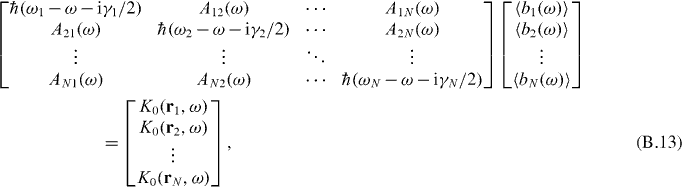
where we consider that the diagonal elements of Aλλ'(ω) are included in the site energies. By solving equation (B.13) and performing Fourier transform, we can obtain  . If we use this result, coupled equations (B.4) and (B.5) can be numerically solved, and the population
  is obtained. Although we have to deal with a considerably large number of combinations of λ and λ' for gλλ' in this solution, we can limit the combinations of λ and λ' in the Hamiltonian for the numerical calculation because gλλ' depends on 1/r3λλ'. In the actual calculation, we have checked the necessary range of |rλ − rλ'| to obtain numerically proper results by comparing the results with different ranges that we take into the calculations.
The population dynamics for the iso-dipole systems can be derived in the same way, but the excitation at a site should be treated separately for x and y. The Hamiltonian corresponding to equation (1) can be written in the form
where α represents the degrees of freedom of direction. Similarly, the other terms can be written as


Now, the straightforward solution of equations (B.4) and (B.5) requires heavy computational load. Fortunately, it can be shown that the effect of the quantum correlation between different sites  appearing in these equations is not essential for the present aim. The computation time is greatly reduced by neglecting this quantity in the calculation. Although this quantum correlation works to expand the population a little bit further, the effect is not prominent and does not change EET characteristics dominated by the geometric features of antenna systems. In figure B.1, we show the results corresponding to those in figure 2 in the main text for both cases with and without the quantum correlation between different sites. By looking at this figure, we can confirm that neglecting the effect of the quantum correlation does not affect our demonstration to compare the EET of the ring-unit system and the single-unit system. Therefore, in the main text, we show the results obtained by this approximate method.
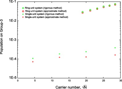
Figure B.1. Group-3 population of the ring-unit system (red: rigorous method; green: approximate method) plotted against the number of rings (against the number of pigments). Group-3 population of the single-unit system (red: rigorous method; green: approximate method) plotted against the number of pigments. The points are N = 20 (360), 25 (450), 30 (540), 35 (630), 40 (720) and 45 (810) for the ring-unit system and N = 20, 150, 400 and 810 for the single-unit system.
Download figure:
Standard image High-resolution imageParameters. The site energy and dipole moment of pigments, taken from B850 of Rps. acidophila referencing Mukai et al [10], are ℏω = 1.55 eV and dλ = 7.1 Debye. dλ = 21 Debye is employed for the imaginary single-unit 21 Debye system and the iso-dipole systems. The dephasing constant is assumed to be ℏγλ = 0.31 meV corresponding to the dephasing time of τd ≃ 4 ps. The center frequency of the incident Gaussian light pulse is located at 1.55 eV with FWHM of 1.2 eV and xy-polarization.
Appendix C.: A realization of population distribution at the dephasing time
A realization of population distribution at the dephasing time (figure C.1).

Figure C.1. A realization of population distribution at the dephasing time. A realization of carrier distribution (a) of the ring-unit system and (b) of the single-unit system. Their population distribution (c) for the ring-unit system and (d) for the single-unit system at the time determined by τd ≃ 4 ps (dephasing time) after only group-1 is exposed to a Gaussian light pulse.
Download figure:
Standard image High-resolution imageTable F.1. The information on statistics of data points for figures in the main text, where N is the carrier number, n is the number of iterations for different realizations of carrier distribution, a.v. is the average value and s.e. is the standard error, that is,  (σ is the standard deviation).
 |
Appendix D.: The discussion of excitation energy transfer and exciton states of a ring, and the effect of the static disorder
We show the spectrum of summed polarization  , pλ(ω): polarization at site (pigment) λ) in one realization of the ring-unit system with 45 rings in figure D.1. Not only the peak for the second-lowest excited state (l.e.s.) but also the peaks for the other states can be seen. This shows that the optically forbidden states can also contribute to inter-ring EET due to non-local interaction between two rings. However, the majority of polarization is located on the second l.e.s., which allows us to assume it is responsible for the majority of EET between rings, and in fact, the behavior of EET efficiency is well reproduced by the iso-dipole system 3 that reproduces the EET, through only the second l.e.s., as shown in the main text. (Please see the good agreement between the pink marks for the ring-unit system and cross marks for the iso-dipole system 3 in figure 3(d) in the main text.)

Figure D.1. Population spectrum for the ring-unit system (ring number N = 45) without static disorder.
Download figure:
Standard image High-resolution imageHere, we show the results in the presence of the static disorder effect. The polarization spectrum is shown in figure D.2, where we assume the same condition as in figure D.1, but with static disorder modeled by Gaussian distribution in site energy with standard deviation of 200 cm−1 [9]. By adding the static disorder, the peaks for other than the second l.e.s. become more significant. We show the EET efficiency in this system in figure D.3. The result shows even when the static disorder is considered, the superiority of the ring-unit system clearly remains though difference between two models is softened. By looking at figure D.2, we see that the third excited state also plays a non-negligible role in EET, and we point that the third excited state also possesses the same three key properties to realize high EET efficiency as the second l.e.s. It is apparent that the third l.e.s. has 'isotropic nature' and 'large occupying area'. In addition, the third l.e.s. realizes the second largest coupling strength between rings after the second l.e.s. among ten excited states [37], which could be interpreted to have a 'large quadrupole moment'. Thus, even considering static disorder, the main state responsible for EET among rings is the second (plus the third ) l.e.s., which does not change the superiority of the ring-unit system demonstrated in the main text.

Figure D.2. Population spectrum for the ring-unit system (ring number N = 45) with static disorder. (Results of 100 patterns of realization are averaged.)
Download figure:
Standard image High-resolution image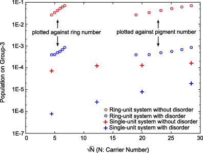
Figure D.3. EET efficiency in the ring-unit system and single-unit system with or without static disorder. (Open circle: the ring-unit system; cross: the single-unit system; red: without static disorder; blue: with static disorder.)
Download figure:
Standard image High-resolution imageAppendix E.: The demonstration using a shorter dephasing time in physiological situation
We have examined the value of the dephasing time τd ≃400 fs, which is for the physiological situation [38]. The corresponding results of EET efficiency are shown in figure E.1. By looking at qualitatively the same behavior, we find that our proposed scenario is not changed though the difference between the two models is softened.

Figure E.1. EET efficiency for the ring-unit system and single-unit system when τ d ≃ 4 ps, 400 fs. (Open circle: the ring-unit system; cross: the single-unit system; red: τd ≃ 4 ps; blue: τd ≃ 400 fs.)
Download figure:
Standard image High-resolution image
Appendix F.: Statistics of data points
The information of statistics of data points is given in table F.1.