
Abstract
KAGRA is a project to construct a cryogenic interferometric gravitational wave detector in Japan. Its mirrors and the lower parts of the suspension systems will be cooled to 20 K in order to reduce thermal noise, one of the fundamental noise sources. One of the key features of KAGRAʼs cooling system is that it will keep the mirrors cooled without introducing vibration. This paper describes the current status of the design, manufacture and testing of the KAGRA cooling system.
Export citation and abstract BibTeX RIS
1. Introduction
To detect gravitational waves, ripples of space-time predicted by Einsteinʼs theory of general relativity, some interferometric gravitational wave detectors have been built and operated, while others are in the process of being planned or constructed [1–5]. Two of these, KAGRA [4] and ET (the Einstein telescope) [5] will enjoy two key advantages over other detectors: they will be located at underground sites with small seismic motion, and their mirrors will be operated at cryogenic temperatures.
The idea of using sapphire cryogenic mirrors was originally proposed in [6]. There are three main advantages of cryogenic sapphire mirrors. The first is the reduction of thermal noise. One of the thermal noise sources, the thermoelastic noise in the mirror substrates, is caused by thermodynamical temperature fluctuations inside the mirrors through their nonzero thermal expansion coefficient [7, 8]. While this thermoelastic noise is approximately constant between 300 K and 50 K, it steeply decreases below around 50 K. The thermoelastic noise finally becomes lower than other thermal noise sources, becoming dominated by Brownian noise in the coating, at around 20 K [9–11]. Therefore, we will set the temperature of the KAGRA mirrors to 20 K. The second advantage of the cryogenic mirrors is that they have less thermal lensing. Thermal lensing is an effect in which the temperature gradient in the mirrors and the temperature dependence of the refractive index cause distortions in the optical wavefronts of a laser beam. This effect in the cryogenic interferometer is negligible mainly due to the higher thermal conductivity and lower dependence of the refractive index on temperature at 20 K [12]. The third advantage is the reduction of parametric instability. Parametric instability is an undesirable resonance of the transversal optical mode in interferometer cavities caused by the laser beam being modulated by elastic vibration of the mirrors. This effect is also suppressed by using the cryogenic sapphire mirrors mainly because of the smaller diameter of the laser beam and the higher Youngʼs modulus of sapphire [13].
Above the KAGRA location in the Kamioka Mine in Japan is a KAGRA prototype called the Cryogenic Laser Interferometer Observatory (CLIO) [14]. CLIO has two 100 m arms, each of which includes a Fabry–Perot cavity. Each of these cavities is formed from two sapphire mirrors, each of which weighs 2 kg; the mirrors are cooled down to 20 K. The most important milestones that have been achieved at CLIO to date are the measurement of the thermal noise of the suspension [15] and the experimental demonstration of the thermal noise reduction by cooling [16].
Currently, the KAGRA project is undergoing the construction of a Fabry–Perot Michelson interferometer with an arm length of 3 km. The mirror will be suspended at the lowest part of the suspension system, which will be made of multi-stage pendulums [17] because the mirror must be a free test mass and thus must be isolated from seismic vibrations. The mirror and the lower part of the suspension system (payload) will be cooled down. KAGRA is intended to achieve a sensitivity that is several orders of magnitude better than that of CLIO by using a longer arm length (3 km), larger mirrors (each mass is 23 kg), a larger seismic attenuation system (SAS), and higher laser power. Because of the larger suspension, one of the issues is that the needed cooling time will be longer [18], as described in section 3.3. Because of the higher laser power (KAGRA: 800 W, CLIO: 0.5 W, where both powers are at the interferometer beam splitter), heat will be absorbed by each mirror at a rate of 1 W (as described in section 3.1) in KAGRA while the corresponding value is on the order of 100 mW in CLIO. In addition, the heat load from scattered light (described in section 3.1) in KAGRA is expected to be larger than that of CLIO.
For these reasons, the KAGRA cryogenic system is required to achieve better cooling performance than that of CLIO while maintaining the same vibration isolation level. To achieve this performance, we made two independent cooling paths for the heat absorbed by the mirror and the heat from scattered light in KAGRA. We also learned an important lesson from CLIO. In CLIO, thermal radiation through the duct shield (described in section 4) was 1000 times larger than our expectation because we had neglected reflections from the duct shield [20]. To reduce this heat load, donut-shaped structures (called baffles) were introduced [21]. In KAGRA, the duct shields were designed on the basis of a detailed calculation from the manufacture stage onward.
This paper describes the current status of the designing, manufacturing, and testing of the KAGRA cooling system.
2. Outline of the KAGRA cooling system
Figure 1 shows the KAGRA cooling system. There are three components in the KAGRA cooling system: cryostats, cryocooler units, and duct shields. Figure 2 shows photographs of one of the KAGRA cryostats, one of the cryocooler units, and one of the duct shields. Each cryostat will cool down the payload in its double radiation shields (where the shields are cooled to 8 K (inner) and 80 K (outer)). Four cryocooler units, which contain double-stage pulse-tube cryocoolers, will be connected to each cryostat. The outer shield of the cryostat is cooled down by the first stages of the four cryocooler units. The inner shield is cooled down by the second stages of two cryocooler units. The second stages of the other two cryocooler units will cool the payload; this comprises the cooling path for the mirror that is independent from the path for the scattered light. The purpose of these units is to extract heat and to simultaneously isolate the vibration of the cryocoolers. The cryocooler unit consists of a pulse-tube cryocooler, vibration reduction stages, and heat conductors [22]. Tests of the cryocooler units themselves, independent of the cryostats, were conducted with a focus on both the cooling power and the vibration [23, 24]. The duct shields are radiation shields used to block thermal radiation through holes in the shields that are necessary to allow the laser beam to pass through [20, 21, 25]. Manufacturing of all four of the cryostats and all 16 of the cryocooler units was completed in 2013. Manufacturing of the duct shields is now underway and will be completed in the next two years.
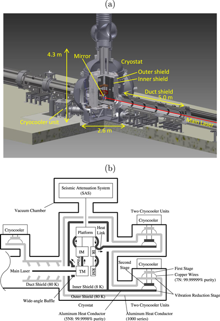
Figure 1. (a) 3D drawing of KAGRAʼs cooling system (drawn by S Koike). (b) Schematic diagram of KAGRAʼs cooling system. The mirror represented by TM will be suspended from a seismic attenuation system (SAS). A cryogenic payload, which consists of the test mass (TM) (the mirror), recoil mass (RM), intermediate mass (IM), intermediate recoil mass (IR), and platform, will be cooled down. These will be surrounded by double (inner and outer) radiation shields. The mirror made of sapphire will be suspended by sapphire fibers [19] from IM. The arrows show the direction of heat flow. Heat from the mirror will be extracted to the IM through the fibers and transferred to platform and then to the IR, and the cryocoolers by thin metal wires called heat links. The cryocooler unit consists of a pulse tube cryocooler, vibration reduction stages, and heat conductors. Duct shields will be installed to reduce thermal radiation through a hole in the shields.
Download figure:
Standard image High-resolution image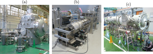
Figure 2. Photographs of (a) a KAGRA cryostat, (b) a cryocooler unit, and (c) a duct shield.
Download figure:
Standard image High-resolution image3. Cryostats
After the manufacturing was completed, all four cryostats were cooled without any payloads connected to the cryostats (as shown in figure 3) in order to analyze the performance of the cryostats themselves. One of the four cryostats contained a half-sized payload that was not connected to the cryostats in order to investigate the cooling time of the payload.

Figure 3. Schematic diagram of the setup employed for the cooling test of the cryostats. The temperature of the inner shield (represented by a white circle) and the part that connects to the payload (a payload connector, represented by the white star) was examined when heat was applied by the heaters. All the holes in the shields were closed by using aluminum plates to block out thermal radiation.
Download figure:
Standard image High-resolution image3.1. Cooling power
When KAGRA is in operation, in each cryostat we expect the following heat contributions, which will have to be extracted:
- 2 W (contribution from heat absorbed by the mirror). This contribution represents the fraction of the laser beam power absorbed by the mirror substrate and its coating. Heat absorption by the mirror substrate (15 cm in thickness) will be below 50 ppm cm−1 [26] of the laser power (800 W at the beam splitter), namely 0.6 W. Heat absorption by the mirror coating will be 1 ppm [27] of the intra-cavity power (400 kW), namely 0.4 W. Together, these sources represent heat absorption of 1 W. To reduce other heat loads to negligible levels compared to this 1 W, the detector configuration is chosen appropriately. The other heat loads, such as thermal radiation or the scattered light from the 3 km beam duct, will be negligible, as described in section 4 and in [28], respectively. However, we designed the cryostats on the basis of a heat deposition into the mirror of 2 W to provide a safety margin5 .
- 10 W (contribution from scattered light). Each mirror will scatter 9 ppm [26] of the intra-cavity power (400 kW) as a result of the scattering from imperfections in the mirror surface (point scattering). We assumed this heat load to be 10 W, including a safety margin. If some scattered light is reflected by the inner shield and recombines with the main laser beam, the scattered light will cause noise (scattered light noise) due to vibration of the inner shield [29]. This scattered light will be caught by a wide-angle baffle, connected to the inner shield.
The two cryocoolers for the payload will extract the heat deposited in the mirror, and the other two cryocoolers for the inner shield will extract the heat contributed by the scattered light. We have designed each cryostat such that the temperature of the part that connects to the payload (represented by the white star in figure 3, hereafter referred to as the payload connector) is at less than 8 K and the inner shield is below 20 K when 2 W is applied to the payload connector and 10 W is applied to the inner shield. The individual cooling powers of each of the four cryostats has been examined [24]. Heaters attached to the payload connector and to the top of the inner shield produced an amount of heat corresponding to the heat deposited in the mirror and the heat deposited by the scattered light, respectively. We investigated the relationship between the heat load from the heaters and the temperature, not only to confirm that the cryostats can extract the required heat load, but also to allow the heat load to be derived from the temperature during operation of KAGRA in the future. Figures 4 and 5 show that all four of the cryostats achieved the designed cooling power except the payload connector of cryostat No. 3. Although the cooling power at the payload connector of cryostat No. 3 at 8 K was 1.8 W, we expect that this will not be a problem since there is still a safety margin of 0.8 W beyond 1 W, which is a realistic estimate of the heat deposited in the mirror.

Figure 4. (a) Achieved temperature when a heat load was applied by the heater attached to the payload connector (represented by the white star in figure 3) [24]. (b) Calculated cooling power from interpolated values at 8 K. Under a heat load of 2 W, corresponding to the amount absorbed by the mirror, the temperature should stay below 8 K. In other words, the cooling power at 8 K should be larger than 2 W. The result shows that cryostats Nos. 1, 2, and 4 satisfied this requirement.
Download figure:
Standard image High-resolution image
Figure 5. (a) Achieved temperature when a heat load was applied by the heater attached to the top of the inner shield (represented by the white circle in figure 3) [24]. (b) Calculated cooling power at 20 K. This value is obtained by (1) fitting a line through the 5 W and 10 W data points for a given cryostat in figures 5(a) and (2) extrapolating this line to its intercept with the horizontal line representing a temperature of 20 K. We put the value for cryostat No. 4 in parentheses since the extrapolation might not be a good approximation because of the nonlinearity of the plot. When a heating power of 10 W, corresponding to the amount expected to be scattered from each mirror and subsequently absorbed by the inner shield, is applied, the temperature should not exceed 20 K. Namely, the cooling power at 20 K should be larger than 10 W. The result shows that this requirement was satisfied.
Download figure:
Standard image High-resolution image3.2. Vibration
Vibrations can be transmitted to the mirrors through two paths: from the SAS and via the heat links from the inner shield. The vibration of the inner shield is an important parameter for calculating the latter and also for estimating the scattered light noise [29]. Our design was to fix the double radiation shields rigidly to the vacuum chamber to reduce the vibration of the shields. To measure this vibration, we installed two accelerometers, which work at cryogenic temperatures, on the inner shield. One accelerometer measured the horizontal vibration and the other measured the vibration in the vertical direction. The result shows that the equivalent gravitational wave amplitude  caused by the vibration through the heat links will be smaller than the design sensitivity of KAGRA after optimizing the design. Further details are provided in [30].
3.3. Cooling the payload
In KAGRA, sapphire fibers and the heat links will be used to extract heat from each mirror to keep the mirror cooled. To reduce the vibrations introduced via the fibers and the heat links, the mass to be cooled should be large, while the fibers and the heat links should be long and thin. This is the main reason that it takes a long time to cool down the payload. One method to reduce the cooling time is to increase thermal radiation. The radiation will be enhanced by coating the payloads with a high-emissivity coating (a diamond-like carbon (DLC) coating). To examine the cooling performance of the payload coated with a DLC coating, we suspended the half-sized payload, shown in figure 6, inside the inner shield. First, we cooled the payload without any heat links (by radiation alone). We have verified that the cooling time of the KAGRA payloads can be reduced from two months to one month by the DLC coating [18].
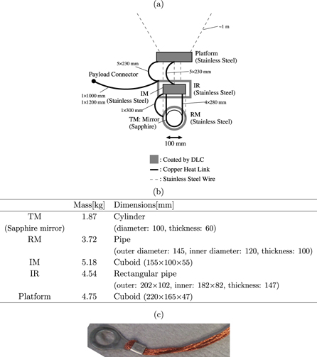
Figure 6. (a) Schematic diagram of the half-sized payload. All parts of the payload except for the mirror were coated with a high-emissivity coating (a diamond-like carbon (DLC) coating). The payload was suspended inside the inner shield by stainless steel wires. The number N and length ℓ of the heat links is represented in the diagram using the format  . One heat link has a cross-section of
  (see the text). (b) Mass and dimensions of the half-sized payload. Some of the inner parts were removed to reduce the mass. Since the mass of the half-sized payload is approximately 1/10 of the actual one, the number of heat links was set such that
  was equal to 1/10 of the actual heat link. (c) Photograph of the copper heat link attached to a crimp contact. The crimp contacts were fixed to the payload or the payload connector using screws.
Download figure:
Standard image High-resolution imageNext, the payload connected to the cryostat by thin copper heat links as shown in figure 6 was cooled down in order to examine the heat link performance. Since radiation cannot cool the payload efficiently below  K, heat conduction via the heat links is necessary. The heat links made of high-purity 7N (99.999 99%) twisted copper wires (the diameter of a single wire is 0.08 mm, and 154 wires are twisted together, yielding a total cross-sectional area of 0.774
  ) were attached to the half-sized payload and the payload connector in the cryostat by crimp contacts. The crimp contacts were made of copper plated with tin. The mirror was also suspended using copper wires. Figure 7 shows the results and the calculation. In this experiment, the cooling by radiation (above
  K) was consistent with the calculation. On the other hand, the cooling by conduction (below
  K) was slower than expected. The possible causes are (1) poor thermal conductivity of the copper wires, (2) contact resistance between the copper wires, the crimp contacts, the payload connector, and the payload, and (3) poor condition of the cryocoolers. We now address each of these possible causes individually: (1) we have measured the thermal conductivity of the heat links. According to the result shown in figure 8, annealing can improve the thermal conductivity of the copper wire considerably. We have confirmed that poor thermal conductivity of the copper wires was one of the causes of the slower cooling. (2) Generally, it is difficult to obtain useful experimental contact resistance data because the contact resistance depends on many conditions such as the shape of the surfaces, the surface roughness, and the stress on the surfaces. However, to reduce the contact resistance, we are developing aluminum/copper wires welded to aluminum/copper blocks, to use instead of the crimp contacts. We will test the performance of these heat links. (3) In this experiment, the 2nd stage cold heads of the cryocoolers for the payload remained at 20 K instead of
  K without any heat load. This issue will be addressed in future experiments. For these reasons, stable operation of the cryocoolers during KAGRA observation is a challenging task.

Figure 7. Result of cooling down the payload with the heat links. Unannealed heat links were used in the experiment. Cooling through thermal conduction was slower than expected. Our expectation was that the cooling speed would be comparable to that calculated assuming annealed heat links. The possible causes for this discrepancy are the poor condition of the cryocoolers and the contact resistance, as explained in the text. For the thermal conductivities of the heat links, please refer to figure 8.
Download figure:
Standard image High-resolution image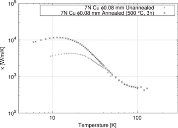
Figure 8. Thermal conductivity measurement of the copper wire. Annealing can strongly improve the thermal conductivity in the temperature range that is important for KAGRA (10–20 K). The values obtained for the 'unannealed' or 'annealed' wires were used in the calculation that produced the results shown in figure 7.
Download figure:
Standard image High-resolution image4. Duct shields
The duct shields were designed from the point of view of thermal radiation and scattered light. Although the mirror must be surrounded by the radiation shield, an opening in the shield is necessary to allow the laser beam to pass through. As described in section 3.3, the amount of heat extractable from the mirror will be limited by the long and thin fibers. Thus, the duct shields are necessary to reduce 300 K thermal radiation. The idea is that the duct shield connected to a cryocooler with higher cooling power due to higher temperature (around 80 K) absorbs heat, which should not be absorbed by the mirrors. Moreover, when the duct shield is designed, the scattered light must be taken into account. The thermal radiation through the duct shields onto the mirror was calculated using a ray tracing model. This calculation was conducted using the commercial ray-tracing software ZEMAX. Figure 9 shows a schematic of the duct shield, as well as a representation of the ray-tracing model of the duct shield. The ray-tracing calculation showed that the duct shield can reduce the heat input to a value of less than 0.1 W [25]. Measurements to evaluate the thermal radiation through the KAGRA duct shields were recently conducted. The measured value agreed well with the calculation and satisfied the KAGRA requirement. We will conduct the same measurement for several duct shields and will publish the results elsewhere.
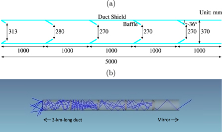
Figure 9. (a) Schematic diagram of a duct shield. To reduce thermal radiation, baffles are installed. The baffles are cone-shaped to catch the scattered light. To absorb thermal radiation and scattered light, the duct made of aluminum 1000 series and baffles made of aluminum 5000 series are treated with ECB (electro-chemical buffing), and coated with a black coating, Solblack, made by Asahi Precision Co Ltd. Five 1 m ducts and five baffles for each duct shield are manufactured, and these baffles are inserted between the ducts. (b) Representation of the duct shield constructed in the commercial ray-tracing software ZEMAX. Rays of thermal radiation were introduced from the left-hand side with a uniform probability distribution in all directions. Based on the Monte Carlo method, the number of rays was increased to make the calculation error less than 1%. Although 107 rays were traced in the calculation, only ten example rays are shown here. One of the ten rays passes through the duct, which corresponds to the heat input through the duct shield.
Download figure:
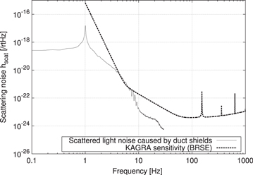
Standard image High-resolution imageThe duct shields can cause scattered light noise since they vibrate and they can reflect the scattered light back to the mirror. We calculated the scattered light noise in the form of a gravitational-wave equivalent amplitude  using [31]. First, the optical power scattered by the mirror, reflected back to the mirror by the duct shield, and recombined with the main laser beam, was calculated using the rays traced in ZEMAX. The angular distribution of the scattered light and the probability of recombination were calculated from the power spectral density of the mirror surface ('Zygo Report 200 mm' in figure 6 of [26]). Although only the duct shield near the mirror was included as a scatterer in this calculation, the entire 3 km long room-temperature duct should be included in the future. Second, the power recombined with the main laser beam and the vibration of the duct shield (here, the seismic motion in Kamioka was used instead) gave the gravitational-wave equivalent amplitude
  . Figure 10 shows the result for
  , along with the design sensitivity of KAGRA. Please note that the calculation results strongly depend on uncertain parameters, such as the angular distribution of the light scattered by the mirrors or by the surfaces of the duct shields. However, we currently expect that the scattered light noise caused by the duct shield will not present a problem since our calculation shows that
  is one order of magnitude smaller than the sensitivity in the target frequency band of KAGRA (above 10 Hz). We plan to measure the vibration of the duct shields to obtain a more precise estimation of the scattered light noise.
Figure 10. Calculated scattered light noise compared with the sensitivity of KAGRA. The noise is approximately one order of magnitude smaller than the sensitivity in the target frequency band of KAGRA (above 10 Hz).
Download figure:
Standard image High-resolution image
5. Summary
The manufacturing of all four of the KAGRA cryostats and all 16 of the cryocooler units has been completed. All the cryostats and all the units were examined in terms of both cooling power and vibrations. Although the cryostats and the cryocooler units were shown to have sufficient cooling power, a further requirement that remains to be achieved in the future is stable operation of the cryocoolers. The current measurements show that an optimization of the payload design can prevent vibration from degrading the sensitivity of KAGRA. The duct shields are currently being manufactured. According to our calculations and experimental verification, they will satisfy the KAGRA requirement in terms of scattered light noise as well as thermal radiation.
Acknowledgments
The cryostats were manufactured by the Toshiba Corporation. The cryocooler units were manufactured by JECC Torisha Co Ltd. Toshiba and JECC Torisha kindly assisted with the experiments reported in this paper. Y Kobayashi manufactured the half-sized payload used in this experiment. G Hofmann, J Komma, and R Nawrodt strongly supported our thermal conductivity measurement of the heat links. This work was supported by (1) the Leading-edge Research Infrastructure Program from the Ministry of Education, Culture, Sports, Science and Technology (MEXT), (2) JSPS KAKENHI grant numbers 25420857, and (3) the Advanced Research Networks component of the JSPS Core-to-Core Program.
Footnotes
- 5
Although the cavity end mirrors only contribute via the coating absorption, while no substrate absorption takes place, we designed all four of the cryostats based on a heat load of 2 W to provide a safety margin. On the other hand, the cryostats for the cavity mirrors that are at the near ends of the cavity will have safety margins of 1 W, and the cryostats for the cavity end mirrors will have safety margins of 1.6 W.