Abstract
One of the most significant limits to the sensitivity of current, and future, long-baseline interferometric gravitational wave detectors is thermal displacement noise of the test masses and their suspensions. This paper reports results of analytical and experimental studies of the limits to thermal noise performance of cryogenic silicon test mass suspensions set by two constraints on suspension fibre dimensions: the minimum dimensions required to allow conductive cooling for extracting incident laser beam heat deposited in the mirrors; and the minimum dimensions of fibres (set by their tensile strength) which can support test masses of the size envisaged for use in future detectors. We report experimental studies of breaking strength of silicon ribbons, and resulting design implications for the feasibility of suspension designs for future gravitational wave detectors using silicon suspension fibres. We analyse the implication of this study for thermal noise performance of cryogenically cooled silicon suspensions.

Content from this work may be used under the terms of the Creative Commons Attribution 3.0 licence. Any further distribution of this work must maintain attribution to the author(s) and the title of the work, journal citation and DOI.
This article was made open access on 7 February 2014
1. Introduction
Long baseline interferometers are used to search for gravitational waves from astronomical sources by sensing the relative displacements of mirrors suspended as pendulums to isolate the test mass mirrors from the effects of seismic noise at the ends of perpendicular interferometer arms [1]. Mechanical dissipation in the pendulum suspensions gives rise to thermal displacement noise [2], x(ω), which may be usefully approximated to [3, 4]:
where T is the temperature, m is the pendulum mass, ϕ(ω) is the mechanical loss angle of the pendulum, ωo is the resonant angular frequency, kB is Boltzmann's constant and ω is the angular frequency of interest. At detection band frequencies of ∼10–200 Hz, displacement sensitivities are limited by thermal motion of the test masses and their suspension elements. For the suspension elements this noise source is particularly significant at lower frequencies (10–30 Hz) [5]. To minimise x(ω) over the detection band, current detector mirror suspensions are fabricated from ultra low mechanical loss materials. Currently, the material of choice is fused silica, which has significantly lower loss than metal wires at room temperature allowing low levels of suspension thermal noise [6–14].
Detectors employing fused silica suspensions include the UK–German detector, GEO600 [15] and upgrades to the US LIGO interferometers [16] that will form the second generation advanced LIGO (aLIGO) detector network. The European Virgo interferometer [17] is also being upgraded to include silica suspensions [18]. However, future sensitivity improvements to these detectors may require moving away from fused silica as a test mass suspension material.
1.1. Silicon as a suspension material
Future upgrades to advanced detectors, together with third generation detectors such as the Einstein Telescope (ET) [19] may look to directly address thermal noise via implementation of cryogenic cooling of the test mass mirror suspensions. This would reduce further the thermal noise of the mirrors, their suspensions and their coatings [19]. For this, fused silica is not an ideal material for the test mass or suspension, since it is known to have a wide mechanical dissipation peak centred around 40 K [10], and also has low thermal conductivity [20] which makes extraction of heat from the incident interferometer laser beam potentially challenging. However, crystalline materials such as sapphire (currently proposed for use in the Japanese cryogenic detector KAGRA [21]) or silicon (the baseline choice for ET) [19] have more attractive low temperature properties and are therefore promising future candidate suspension materials. In particular, at temperatures around 18 K and around 125 K the thermal expansion coefficient of silicon goes through zero [22], and hence the dissipation due to thermoelastic damping is essentially negligible around these temperatures [23]. Our studies [24] have also indicated that the surface loss of silicon in the form of flexures at low temperature may be at least an order of magnitude lower than that of fused silica. Initial studies in [25, 26] have shown the feasibility of pulling crystalline fibres by the pedestal growth technique.
1.2. Suspension thermal noise
Two fibre geometries are of particular interest for use in detector suspensions—rectangular cross section suspension 'ribbons', or circular cross section 'fibres' [2]. The mechanical loss of these suspension elements can be calculated from the individual loss components—a loss ϕbulk associated with the bulk material making up the fibre, a frequency independent component from loss arising at the fibre surface, ϕsurface fibre, and a frequency dependent thermoelastic loss component, ϕthermoelastic(ω):

with the surface loss given by:

where hϕs is the product of the mechanical loss of the material surface, ϕs, and the depth, h, over which surface loss mechanisms are believed to occur. From [24] we take the value of 5 × 10⁻¹³ as hϕs. For rectangular cross section ribbons, the surface loss takes the form [27]:

where x is the width of the ribbon, and y is the thickness (in the direction of bending).
Thermoelastic loss for a suspension fibre, which generates motion via the thermal expansion of the material due to localized variations in temperature [28–30] is given by:

with


where Y is the Young's modulus of the fibre, C is the specific heat capacity, κ is its thermal conductivity, ρ is the density, α is the coefficient of linear thermal expansion, σo is the static stress in the fibre due to the suspended load, is the thermal elastic coefficient, d is the diameter of the fibre in the circular cross-section case, and y is the thickness of the ribbon in the rectangular cross-section case.

The total mechanical loss of the system for the pendulum suspension is less than that of the material as often a significant amount of energy is stored in the lossless gravitational field. This is dissipation dilution, D:

where D is evaluated for each resonant mode [29, 31]:

with L the length of the suspension, F is the tension in each fibre, I is the second area moment of the fibres, n is the number of fibres and γ takes the value of unity if the wires bend only at the top, and the value 2 if they bend both top and bottom [2].
It is clear that surface loss, thermoelastic loss and dissipation dilution of suspension elements are dependent on the cross-sectional dimensions of the suspension fibres. For fused silica suspensions these values were chosen carefully to minimise the mechanical loss and provide appropriate resonant modes of the suspension [32]. However, for low temperature detectors using silicon suspensions, additional constraints are present. This paper presents analysis of silicon suspension performance focusing on two of these additional factors that will have a significant bearing on the fibre dimensions—namely extraction of heat injected by the main interferometer laser beam; and the tensile strength of silicon.
2. Design considerations for silicon suspension fibres
2.1. Extraction of deposited laser energy
Cryogenic mirrors will experience heating from absorption of a fraction the laser light incident on the mirror surface. Radiative cooling may be possible at higher temperatures (>∼120 K) [33], but at lower temperatures conduction of the heat along the suspension fibres will be the primary mechanism for extracting the heat deposited in the test mass [34].
This therefore places a limit on their cross sectional area—if the fibres are too thin then this will inhibit heat extraction. This limit on minimizing fibre cross-section directly affects the resulting thermal noise performance of the suspension via the achievable dissipation dilution and the surface loss.
The minimum radius of circular fibre required can be estimated using the conduction equation [35]:

where H is the heat flow along the fibres, A is the cross sectional area of an individual fibre (with 4A being the total cross sectional area of the 4 suspension fibres available for heat conduction), and k(T) is the temperature dependent thermal conductivity. For a fibre length L, the required area, A, to precisely extract the deposited heat is then:

where T1 and T2 are the lower and upper mass temperatures respectively. Values for the temperature dependent thermal conductivity over much of the temperature range were taken from [22].
The thermal conductivity of a material is limited by phonon scattering, and at low temperatures (<40 K), will eventually be limited by the sample's smallest dimension, due to scattering at the material surface boundaries [36]. In this case, the thermal conductivity values used were set by the smallest dimension of the samples:

where tmeas is the minimum dimension of the relevant sample in [22], and t is the minimum dimension of the suspension ribbon/fibre.
For future detectors such as the ET, the circulating laser powers in the interferometer may be of the order of 18 kW, with an anticipated worst case mirror absorption of 1 part per million [19], meaning 18 mW will be required to be extracted from the test mass. To set the framework for the physical demands on suspension performance we make the simplified assumption that the tops of the fibres are held at liquid helium temperature of 4 K, and we then vary the desired temperature of the test mass. Several lengths of suspension were also analysed: 60 cm (as in aLIGO) and two larger suspensions at 100 cm and 140 cm respectively. Considering effects of suspension length on performance is important, as longer fibres give greater dilution through equation (9). However the longer the fibre, the larger its dimensions need to be to extract the heat (see equation (12)). The minimum radius of circular fibre required to extract the 18 mW absorbed power is shown in figure 1(a), and the minimum thickness of a ribbon with 5:1 width:thickness aspect ratio is shown in figure 1(b).

Figure 1. (a) Minimum radius of fibre required to extract heat from a mirror resulting from 1 ppm absorption assuming an 18 kW incident beam. (b) Minimum thickness of 5:1 aspect ratio ribbon required to extract 1 ppm absorption from an 18 kW incident beam.
Download figure:
Standard image High-resolution imageIt can be seen in figure 1 that the required fibre diameter rapidly increases as temperatures decrease below 40 K, as thermal conductivity drops significantly at these temperatures. This means a significantly thicker fibre is required to extract the deposited energy as the desired test mass temperature decreases. This in turn influences the observed dissipation dilution of a suspension through equation (9), as shown in figure 2.

Figure 2. (a) Dissipation dilution of suspensions using minimum radius of fibre required to extract 1 ppm absorbed from an 18 kW incident beam. (b) Dissipation dilution of suspensions using minimum thickness of 5:1 aspect ratio ribbon required to extract 1ppm absorbed from an 18 kW incident beam.
Download figure:
Standard image High-resolution imageDissipation dilution is seen to be greater by a factor of ∼2 for rectangular ribbons as compared to the circular fibres at equivalent temperatures—this is because the required ribbon thickness in the direction of bending is smaller than the equivalent fibre radius, as was shown in figure 1.
Figure 3 shows the surface, bulk and thermoelastic loss components of these ribbons and fibres at 10 Hz, where we assume a worst case where the fibre is at the same temperature as the test mass along its length5. For temperatures below ∼40 K, thermoelastic loss drops away and is no longer a dominant or significant loss term for circular fibres. For the rectangular ribbons surface loss is dominant over most of the temperature range. However, as fibre length (and therefore thickness) increases the thermoelastic loss rises, to be about equal to surface loss at temperatures of ∼70–90 K for the 140 cm long suspension. Longer suspensions than this would see the thermoelastic loss start to rise above surface loss at these temperatures.

Figure 3. (a) Surface, bulk [38] and thermoelastic loss components for minimum radius of fibre (which varies with the temperature, from figure 1) required to extract 1ppm absorption from an 18 kW incident beam, calculated at 10 Hz. (b) Surface, bulk and thermoelastic loss components for minimum thickness of 5:1 aspect ratio ribbon (which varies with the temperature, from figure 1) required to extract 1 ppm absorption from an 18 kW incident beam, calculated at 10 Hz.
Download figure:
Standard image High-resolution imageIn both cases, the significant fall off of thermoelastic loss at low temperatures is due to both the approach of the null in thermal expansion coefficient of the silicon at ∼18 K, and also because thermoelastic loss is directly proportional to temperature, as displayed by equation (5).
Bulk loss is taken from measurements by McGuigan [38]. These show a peak at ∼13 K, with the bulk dropping away to leave the other loss components dominating in the region from ∼17 K upwards. The loss peak at 13 K has not been observed in [39], however we include here as a worst case.
The displacement thermal noise for a single suspension, calculated at 10 Hz via equation (1) is shown in figure 4(a) for circular fibres and figure 4(b) for ribbons for a 200 kg test mass (the current design choice for the ET [40]). Ribbons are seen to have better thermal noise performance—this is due to their higher dissipation dilution. In both ribbon and fibre cases, only very small gains in noise performance are seen for temperatures less than ∼40 K. Indeed, at temperatures between 20 and 40 K the observed thermal noise begins to level off—this is due to the much lower dissipation dilution experienced at these temperatures—this being a result of a much larger radius fibre/thickness of ribbon that is needed to maintain the low test mass temperature. At lower temperatures than this the peak in bulk loss causes a low temperature peak in noise.

Figure 4. (a) Displacement thermal noise of a single suspension for different minimum radius of fibre (which varies with the temperature, from figure 1) required to extract 1 ppm absorption from an 18 kW incident beam, calculated at 10 Hz for 200 kg test mass. (b) Displacement thermal noise for single suspension for minimum thickness of 5:1 aspect ratio ribbon (which varies with the temperature, from figure 1) required to extract 1ppm absorption from an 18 kW incident beam, calculated at 10 Hz.
Download figure:
Standard image High-resolution imageThe flattening off of the noise in 20–40 K temperature gives the opportunity to broaden the range of potential operating temperatures in the low temperature regime, without significant impact on performance. Due to the technical challenge of ensuring no external heat leaks into the system, temperatures at the higher end of this range will potentially be an easier goal to meet, so for the remainder of this paper we will analyse for suspensions running at 40 K.
It is of note that the suspension thermal noise at 40 K is between a factor of 40–76 times lower (depending on the suspension length) than that of the current room temperature silica suspensions in aLIGO for circular fibres, whose thermal noise at 10 Hz is ∼1 × 10⁻¹⁹m Hz−1/2 [41, 42]. For rectangular cross-section ribbons the noise is a factor of 58–113 lower depending on the suspension length. However, the calculations above are based solely on the minimum fibre dimension required for desired heat extraction from a test mass. Another key parameter needed to practically fabricate a cryogenic mirror suspension is an appropriate level of tensile strength in the silicon suspension fibres.
2.2. Tensile strength of silicon
2.2.1. Previous studies
Untreated silicon is a brittle material, and will fail catastrophically at room temperature, rather than experiencing significant plastic deformation [43, 44].
3 point bending strength test measurements have been undertaken on microscale silicon 'whisker' samples by Pearson et al [43] where fracture stresses of on average ∼1–2 GPa, peaking at 5 GPa were measured on samples 20–100 µm in diameter. A result of note in [43] was evidence that fracture stress decreases significantly with increasing cross section of the silicon sample. All samples used in this study were significantly smaller in cross section (typically 3 × 10⁻⁴ – 5×10⁻² mm2) than would be required for silicon ribbons/fibres that are likely to be used in future gravitational wave detectors (likely to be of the order ∼0.25–10 mm2).
Tensile strength studies on samples of larger cross section of 0.5 mm2 by Sylwestrowicz [45] have shown that the strength of larger cross section silicon samples at room temperature is significantly lower at around 200 MPa. The likely reason for this decrease in observed strength in larger samples, and fracture of macroscopic scale silicon samples in general, is localized areas of high stress within the material [45] including surface Griffith cracks [46] on the material edges, bulk defects such as dislocations and impurities in the silicon itself [43, 47]. The small cross section samples used by Pearson [43] are likely to have higher strengths as the probability of these defects reduces with sample size.
It is of note that studies of silicon wafer bending using circular wafers supported on an annulus holder of smaller diameter than the wafer, with the load force applied at their centre, have shown that the bulk silicon material can be significantly stronger, with maximum stresses of 6.9 GPa reported by [47] and 8.8 GPa by [48]. However, these tests are not analogous to the scenario in which silicon will be used in gravitational wave detectors suspensions, so these values should be treated with care. Since the wafers were held by the annulus holder, effects on fracture stress from the wafer edge quality were removed from the experiment. In gravitational wave detector suspensions, the edges of the suspension ribbons/fibres will experience tensile and bending stresses when hanging as pendulums, and therefore the effects of the edges are of key importance in the observed strength. More generally, the surface quality of any area of the ribbon or fibre may be a key limiting factor in the observed strength. It therefore is clear that tensile strengths of samples of the typical macroscopic cross sections required for suspension fibres are likely to have lower strength than the maximum literature value of 8.8 GPa, and that the surface and edge quality for suspension fibres is likely to be critical for the observed ultimate tensile strength.
2.2.2. Measurement of tensile strength of silicon
An initial experimental study of tensile strength at room temperature has been undertaken. In this study a total of 93 silicon samples of 9 different varieties were tested, with 5 different variations of standard surface treatments undertaken, to give an indication of their effects. Two crystal axis orientations of silicon wafer, 〈1 0 0〉, 〈1 1 0〉, were available for test. Sample details are given in table 1.
Table 1. Details of silicon suspension samples used in tensile strength tests.
| Sample set | Silicon orientation | Sample dimensions (mm) | Edge quality | Surface treatment |
|---|---|---|---|---|
| 1 | 〈1 1 0〉 | 45 × 2.2 × 0.5 | Mechanically | None |
| polished | ||||
| 2 | 〈1 0 0〉 | 45 × 2.2 × 0.5 | Mechanically | None |
| polished | ||||
| 3 | 〈1 0 0〉 | 45 × 3.5 × 0.5 | Etched | None |
| 4 | 〈1 1 0〉 | 45 × 2.2 × 0.5 | Mechanically | Front and back surfaces |
| polished | coated with Si3N4 | |||
| 5 | 〈1 0 0〉 | 45 × 2.2 × 0.5 | Mechanically | Front and back surfaces |
| polished | coated with Si3N4 | |||
| 6 | 〈1 0 0〉 | 45 × 2.2 × 0.5 | Mechanically | Entire sample |
| polished | wet oxidized | |||
| 7 | 〈1 1 0〉 | 45 × 2.2 × 0.5 | Mechanically | Entire sample |
| polished | wet oxidized | |||
| 8 | 〈1 1 0〉 | 45 × 2.2 × 0.5 | Mechanically | Front and back surfaces |
| polished | coated with Si3N4, | |||
| edges wet oxidized | ||||
| 9 | 〈1 0 0〉 | 45 × 2.2 × 0.5 | Mechanically | Front and back surfaces |
| polished | coated with Si3N4, | |||
| edges wet oxidized |
The samples were rectangular cross section, with all apart from sample set 3 mechanically cut out of standard 0.5 mm thick silicon wafers, with the edges then mechanically polished. Sample set 3 was chemically etched from wafers to provided a comparison with etched samples.
Sample sets 4, 5, 8 and 9 were wet oxidized in a saturated atmosphere at 1000 °C for 1 h, with a range of oxide thicknesses from 100–300 nm measured after oxidation, this being done using a Sentech SE850 spectroscopic ellipsometer [49] prior to breaking the samples.
Since clamping the samples mechanically could cause surface damage, or be prone to slippage during testing, the samples were bonded between two metal attachment pieces using Aradite 2012 epoxy adhesive as shown in figure 5(a). Prior to curing of the bonding adhesive, the sample was set in an alignment jig to ensure the samples were aligned consistently and parallel to the attachment pieces, as in figure 5(b). Once cured, the samples were mounted on an adaptable tensile strength testing apparatus [50] as shown in figure 5(c). Universal joints were installed above and below the sample to ensure that minimal bending or torsional forces would be experienced by the samples.

Figure 5. (a) Silicon sample bonded between metal slotted attachment pieces. (b) Sample set in alignment. (c) Sample installed in tensile strength test apparatus.
Download figure:
Standard image High-resolution image2.2.3. Strength results
The tensile strength test results for the nine sample sets are shown in figure 6.

Figure 6. Strength test results for nine different types of sample, showing individual data points and average values with their standard error.
Download figure:
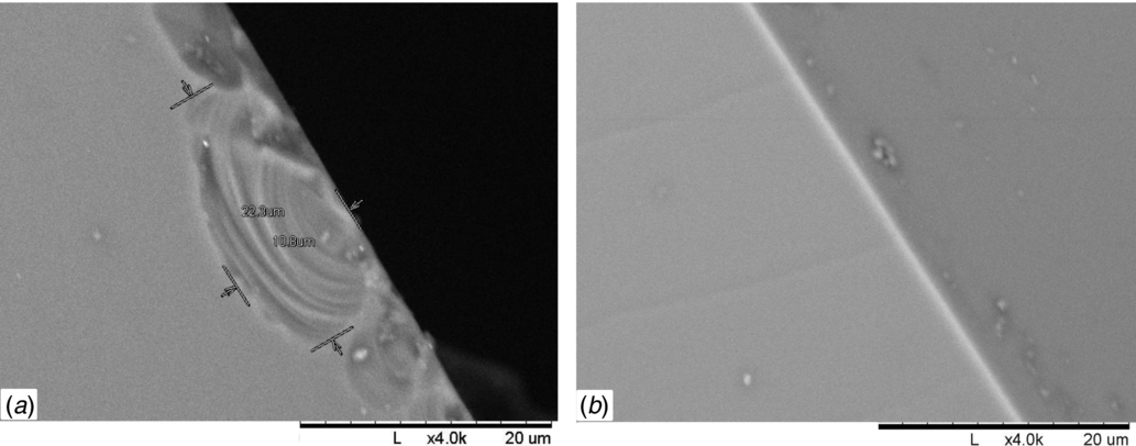
Standard image High-resolution imageIt appears that the samples with etched edges (set 3) are stronger by on average ∼50% with an average strength of (210±17) MPa compared to the equivalent unetched samples in sets 1 and 2 which had average strengths of (147±13) MPa, (133±13) MPa respectively. Sets 1 and 2 are also within error indicating that the orientation of the silicon sample is not a dominant influence on strength. The results for the etched samples are consistent with the maximum strength of ∼200 MPa reported in [45] at room temperature, which had a similar etched surface treatment. Indeed a significant number of the datapoints presented here show higher strength than 200 MPa – higher than those of [45]. The lower values of strength seen for sample sets 1 and 2 imply that the surface edge quality is a limiting factor on strength, as could be expected. Figure 7 shows an SEM image of typical sample edges showing damage as could be expected from mechanical polishing, with chips of order of 10–20 µm in size visible.

Figure 7. SEM images of edge quality of (a). Mechanically polished sample (b). Etched sample.
Download figure:
Standard image High-resolution imageThe samples with Si3N4 on their front and back surfaces (sets 4 and 5) were seen to be no stronger than their untreated equivalents in sets 1 and 2. This implies again that the surface quality of the untreated edges is limiting the strength. Samples which had these edges oxidized (sets 8 and 9) were seen to have a notably increased strength, as were those with all surfaces oxidized. This supports the postulation that surface quality is limiting strength, and it is clear from these results that suitable surface treatment can enhance the strength of silicon suspension elements.
2.2.4. The effect of strength on suspension thermal noise performance
Mechanical loss was again modelled as in section 1.2 but in this case the dimensions of the fibres/ribbons were chosen from strength values. The thermal noise performance was then calculated for the pendulum (using equation (1)), vertical bounce and first two violin modes of the suspension, as below. A 200 kg test mass is assumed, this being the current design choice for the ET [40].
Vertical mode.
This resonance experiences no dissipation dilution [2] so the value of D was taken as 1 in the calculations. Vertical motion couples weakly into horizontal motion if the interferometer arms are long enough such that the test masses at the arm ends do not hang parallel, due to the curvature of the earth. If we assume similar cross coupling from vertical to horizontal motion as in current advanced detectors, a value of 0.1% is taken [51, 52]. Therefore, the contribution to horizontal thermal noise rms displacement from the vertical mode is then:

where ϕtotal vertical (ω) is the total loss for the vertical mode, and ωvertical is the vertical resonant mode frequency.
Violin modes.
The violin mode thermal noise spectrum for the first two violin modes was calculated using [53]:
where, mfibre is the mass of each fibre, ωviolin is the respective violin resonant mode frequency, v is the respective violin mode number and ϕtotal violin(ω) is the total loss for the violin mode, calculated using [54]:

Noise spectra.
Figure 8 shows the noise spectra at 40 K for the cases of fibres with a stress of 133 MPa (equivalent to the average 〈1 0 0〉 strength test undertaken in section 2.2.3, figure 6), 40 MPa (equivalent to the average 〈1 0 0〉 strength test undertaken in section 2.2.3, but including a factor of ∼3 safety), 300 MPa wet oxidized fibres (this stress is taken from the average value seen from the oxidized sample set 7 in section 2.2.3, figure 6), and 573 MPa case, which is equivalent to the fibre diameter required to extract the deposited detector laser energy (taken from section 2.1). Figure 9 shows the equivalent for rectangular cross section ribbons. All suspensions are 1 m in length. In both figures 8, 9 the design sensitivity of ET (referred as ET-D [40]) is shown for comparison.

Figure 8. Displacement thermal noise of single 1 m long silicon mirror suspensions, for circular cross section fibres.
Download figure:
Standard image High-resolution image
Figure 9. Displacement thermal noise of single 1 m long silicon mirror suspensions, for rectangular cross section ribbons.
Download figure:
Standard image High-resolution imageIt can be seen from figures 8, 9 that both silicon ribbons and fibres show a significant potential gain in performance over the current aLIGO room temperature suspensions. For the 40 MPa strength limited case a factor of improvement in displacement noise of 18 times is seen at 10 Hz for circular fibres. This is limited by thermoelastic loss. If fibre strength is improved, the gain in performance also increases with a factor of 39 improvement seen at 133 MPa, increasing to a factor of 57 at the heat extraction limited case of fibres where the stress in the fibres would be 573 MPa. As the strength increases and the fibre gets thinner, the thermoelastic peak frequency increases, meaning less thermoelastic loss is seen at low temperature. Equivalent rectangular cross section ribbons show slightly greater performance gains, with a gain of ∼100 at the heat extraction limited case with ribbons having a stress of 573 MPa. One potential advantage of the rectangular geometry is that the violin modes are at higher frequencies than those in the equivalently stressed circular fibre suspensions. Depending on the frequency of gravitational wave source that may be of interest, this may prove desirable. In both cases careful choices may need to be made in fibre design to place the vertical bounce mode resonance at a frequency that does not impinge too far into the detection band—as can be seen from figures 8, 9 the vertical mode comes down in frequency as strength increases (and therefore fibre cross section decreases).
Gains beyond the heat extraction limiting cases would require fibres/ribbons to be thinner still, and therefore methods of extracting the deposited detector laser energy that do not rely on conduction up the suspension fibres would need to be implemented.
These results show that improving strength via surface treatments that have low or negligible effect on the surface loss value is key in improving the thermal noise performance of future silicon suspensions—it would be required for this suspension to meet the noise requirement for ET, for example. A limit is placed on the ultimate noise performance of any given suspension by the minimum thickness of fibre required to extract the deposited heat. Improving this requires both an increase in the strength of silicon, and additional methods of cooling the test mass other than extracting heat only via conduction up the suspension fibres. The oxidized fibres have significantly greater surface loss hϕs value of 1 × 10⁻¹⁰ [55] as compared un-oxidized silicon (hϕs value of 5 × 10⁻¹³ [24]), explaining their higher thermal noise as shown in figures 8, 9. This highlights that while the surface treatment undertaken successfully increases the fibre strength (and therefore reduces the required cross sectional area and increases dissipation dilution) it does significantly increase the material's surface loss, affecting the ultimate performance. Therefore future surface treatments need to be shown to have low mechanical loss as well as increasing the strength of the silicon.
3. Fibre profiles
Previous studies [29, 56] have shown that for fused silica fibres the geometry of the end of the fibre can have a significant effect on the actual dissipation dilution. Therefore, finite element modelling of fibre necks similar to that undertaken in [29] was done to analyse the influence of the neck. The strength limited 133 MPa ribbon and fibre geometries were chosen, with 1 m suspensions and linear taper necks of equal cross sectional area modelled at the fibre ends, as shown in figure 10.

Figure 10. (a) Rectangular cross section fibre neck. (b) Circular cross section fibre neck.
Download figure:
Standard image High-resolution imageNeck length was varied from 0 to 50 mm, and the dissipation dilution as a function of this length is shown in figure 11.

Figure 11. Dissipation dilution as a function of neck length for rectangular and circular cross section silicon fibres.
Download figure:
Standard image High-resolution image
For both ribbons and fibres, the decrease in dissipation dilution is much less than was seen in aLIGO silica case [29], with the addition of a 50 mm long linear taper neck reducing the dilution by ∼21% for the rectangular ribbon, and ∼7% for the circular case. As such, this effect is relatively small. The reason that dissipation dilution is not as greatly reduced as was seen in studies of fused silica fibre geometries is a combination of the Young's Modulus of silicon being greater than silica, and the increased thickness of the silicon elements shown here. Both these effects mean the fibres are much stiffer to bending and therefore bending occurs further down the fibre, further from the neck, reducing the influence of the neck on the dilution. Only very long necks (>50 mm) would start to cause a significant decay of the dissipation dilution and therefore noise performance. However, fibres with such necks are unlikely to be chosen for use in future gravitational wave detectors.
4. Conclusions
Silicon is a promising alternative material for future upgrades to existing gravitational wave detectors, and third generation detectors running at cryogenic temperatures in order to reduce thermal displacement noise.
It has been demonstrated that there are two important considerations that will place limits on thermal noise performance for future silicon suspensions—namely extracting the heat deposited in the test mass via the main interferometer laser beam, and the tensile strength of the silicon suspension fibres/ribbons. In the case of heat extraction being the limiting case a displacement noise level of ∼1–1.5×10⁻²¹ m Hz −1/2 is attainable for a 200 kg suspension at test mass temperatures of ∼20–40 K. This is approximately a factor of 100 times gain as compared to a room temperature fused silica aLIGO suspension.
Tensile strength tests have demonstrated that currently suspension performance will be limited by the strength of the silicon fibres/ribbons. Typical strength of untreated silicon was seen to be ∼133 MPa, and fibres and ribbons supporting a conservative 1/3 of this load were shown to have a factor of 18 improvement in displacement thermal noise over aLIGO, with ribbons coming close to satisfying the ET design requirement. Further improvement in strength may be possible through surface treatment of silicon, which may permit improved displacement noise performance through thinner fibres and improved dissipation dilution.
It has been demonstrated also that the end shape of fibres will be less critical than has been seen for fused silica room temperature suspensions, with the change in dissipation dilution due to fibre necks being ∼21% for rectangular ribbons and ∼7% for circular fibres for the longest 50 mm necks.
These results are very promising for future detectors, and if such gains are implemented will provide a significant enhancement in the distance into space that will be able to be probed for gravitational wave emissions.
Acknowledgments
We are grateful for the financial support provided by Science and Technology Facilities Council (STFC) under RCUK award reference ST/J000361/1, the Scottish Funding Council (SFC), the Royal Society, the Wolfson Foundation, and the University of Glasgow in the UK. IW Martin is supported by a Royal Society Research Fellowship. We would like to thank SFB TR7 project of the German Science Foundation. We would like to thank our colleagues in the LSC and VIRGO collaborations and within SUPA for their interest in this work. This paper has LIGO document number P1300153.
Footnotes
- 5
Possible effects from non-equilibrium thermodynamics are beyond the scope of this paper and an area of current research [37].