
Abstract
Carbon nanotube (CNT) aerogel sheets produce smooth-spectra sound over a wide frequency range (1–105 Hz) by means of thermoacoustic (TA) sound generation. Protective encapsulation of CNT sheets in inert gases between rigid vibrating plates provides resonant features for the TA sound projector and attractive performance at needed low frequencies. Energy conversion efficiencies in air of 2% and 10% underwater, which can be enhanced by further increasing the modulation temperature. Using a developed method for accurate temperature measurements for the thin aerogel CNT sheets, heat dissipation processes, failure mechanisms, and associated power densities are investigated for encapsulated multilayered CNT TA heaters and related to the thermal diffusivity distance when sheet layers are separated. Resulting thermal management methods for high applied power are discussed and deployed to construct efficient and tunable underwater sound projector for operation at relatively low frequencies, 10 Hz–10 kHz. The optimal design of these TA projectors for high-power SONAR arrays is discussed.
Export citation and abstract BibTeX RIS
1. Introduction
Carbon nanotube (CNT) sheets encapsulated in inert gases show promise for transparent and flexible audio loudspeakers and high-power sound projectors for SONAR. Thermoacoustic (TA) sound generation combines the principles of a heat engine, Carnot's theorem, and fluid dynamics at the nanoscale. The separation of the source of mechanical forces from the peculiarities of vibrating plates interacting with the external media gives additional degrees of freedom for the design of TA devices. Advantages of this technology in the audio industry include ultra-lightweight materials, thin device profile, flexibility, and low production cost.
The utilized transparent CNT aerogel sheets have about the density of air and the electrical conductivity of some metals [1]. They have been used for TA transducers that can operate in harsh gaseous environments [2] and underwater [3]. The open-to-air CNT sheet (open system) was found to generate smooth-spectra sound emission over a wide frequency range (1–105 Hz). However, at low frequencies f, where the need for high-power conformal projectors is great, the sound generation efficiency of open systems is disappointingly low. Other challenges are that the air-like density of CNT sheets results in low mechanical strength and they have high sensitivity to the environment at the high surface temperatures necessary for high-power TA sound generation.
A recent study has attempted to address these challenges by using protective encapsulation of free-standing CNT sheets in inert gases [4]. The encapsulation of free-standing multiwall carbon nanotube (MWNT) sheets in inert gases between two flat membranes (or rigid plates) is a promising methodology for providing both sheet protection and enhancement of TA sound generation efficiencies at low frequencies. Aliev et al explored the effects of different thermodynamic regimes on the fundamental efficiency for TA sound generation [4]. They obtained enhancement of TA sound generation efficiency by (i) encapsulating free-standing MWNT sheets in high molecular weight inert gases, (ii) using vibrating membranes or rigid plates with high resonant quality factors, (iii) reducing the volume of the enclosure, and (iv) modulating an applied high frequency carrier current with a low frequency resonant envelope. Despite the low acoustic power density achieved so far (∼0.05 W cm−2), the wide band and high gravimetric acoustic power density (>50 W kg−1) of CNT-based TA projectors and the capability to fabricate thin (<1 mm), flexible, large surface area (>1 m2), lightweight devices suggests opportunities for new applications in both air and underwater platforms.
The variation of temperature and pressure in the vicinity of an open CNT heater induces sound wave propagation in the surrounding medium. Increasing the thermal gradient created between the surface of the CNT sheet and the surrounding medium within the thermal diffusion length (ld = (2α/ω)1/2, where α is the thermal diffusivity and ω is the angular frequency of temperature modulation) results in increased sound pressure intensity. Therefore, high applied electrical power is required to achieve high sound intensity and energy conversion efficiency. A higher applied power Ph produces an increased temperature gradient (equation 12 in [4]) and subsequently higher sound pressure and Carnot's efficiency. The extremely low heat capacity of the aerogel density CNT sheet and the small but finite heat capacity of air are accompanied by low thermal conductivities to external heat sinks, which lead, at high applied ac power, to an accumulation of heat in the vicinity of the heater. This elevated background temperature decreases the efficiency of the TA projector. Heat dissipation from the small volume interior of encapsulated devices is restricted, and becomes the main obstacle limiting the acoustic power density of the TA projector.
We address here the thermal management issues in TA projectors using a comparative experimental study of open and closed systems. We systematically investigate the effects of heat accumulation on the fundamental efficiency of TA sound generation. First, to increase the accuracy of temperature estimation on the surface of the a nanometer-scale thick CNT heater, we combine temperature measurements using the temperature coefficient of resistance of the CNT sheet with remote infrared (IR) camera measurements using black-body emissivity, which is evaluated from the dependence of optical absorption for the given number of CNT layers in the TA device. Second, we evaluate the maximum ac power density applicable to the CNT sheet in vacuum and argon to estimate the power limits of the TA transducers. Finally, we study dc heat dissipation from the interior of the encapsulated TA transducers, using as variables the spatial separation of the CNT sheets, different heat sinks, and the use of interdigitated electrodes to provide enhanced thermal conduction.
2. Results and discussion
2.1. Temperature measurement
The thermoacoustically created variation in gas pressure p is proportional to the temperature variation ΔTa on the surface of a free-standing MWNT sheet: p ∼ ΔTa/T0, where T0 is the ambient temperature. Therefore, reliable measurement of the temperature on the surface of resistively heated CNTs is a crucial step for thermal management of a TA device. Direct contact measurement of the temperature on the surface of a free-standing CNT sheet is impossible due to nanoscale structure and fragility of the sheet. Temperatures on the surface of single-walled carbon nanotubes (SWNTs) [5] and graphene [6] have been remotely measured using the temperature-sensitive position of the G peak in Raman spectra. However, the temperature dependence of Raman shift ω is small, even for SWNTs (ω−1dω/dT ∼ 10−5 K−1), and the much wider G peak width for MWNTs grown by catalytic chemical vapour deposition (CVD) method leads to a relatively low resolution of the peak position. This suggests that an alternative and simpler means to extract the temperature of free-standing MWNT sheets should be developed.
Remote temperature measurement using integrated black-body radiation power requires knowledge of the surface emissivity of the CNT sheet ε, which depends upon the polarization of emitted light with respect to the CNT alignment direction and sheets' areal density [7]. Here, we combine temperature measurements for free-standing MWNT sheets using the temperature coefficient of resistance (TCR = (ΔR/R0)/ΔT) [8] with optical transmission measurements to extract the needed ε and thereby compute the correct temperature from optical measurements. Despite the near-perfect black-body behavior of the CNT forest (ε = 0.98–0.99) and the relatively high emissivity of roll-pressed SWNT forest (ε = 0.75 [9]) and bucky-paper, the emissivity of single layer MWNT aerogel sheets is very low because of low sheet density and thickness. The emissivity of an MWNT sheet can be directly estimated from the optical absorption coefficient α using Kirchhoff's law of thermal radiation (ε = α). Here, the dimensionless coefficient of absorption (or the absorptivity) α is the fraction of incident light (power) that is absorbed by the body when it is radiating and absorbing in thermodynamic equilibrium. The visible optical transmittance spectra of single, double, and triple layers of superimposed MWNT sheets, shown in figure 1 for parallel and perpendicular light polarization, respectively, show the increase in absorption with increase in the number of stacked sheet layers. The pronounced absorption peaks at 495 nm (S11) and 446 nm (S22) suggest the existence of semiconducting few-wall or SWNTs in predominantly MWNT sheets.

Figure 1. The transmittance spectra of single (blue), two superimposed (red), and three superimposed (green) MWNT aerogel sheets for light polarized perpendicular (a) and parallel (b) to the MWNT alignment direction were obtained using a Perkin Elmer Lambda 900 UV–Vis/NIR spectrophotometer. The inset in (a) shows a TA device (resonance frequency fr = 2.3 kHz) comprising such single, double, and triple MWNT sheets strips suspended between two glass plates (75 × 50 × 1 mm2 Corning glass microscope slides). These sheets were drawn from a 180 μm high forest.
Download figure:
Standard image High-resolution imageBecause the majority of remote temperature detectors work in the 3–5 μm and 8–14 μm IR-transparent windows, we recorded the transmittance spectra of one to six layered MWNT sheets using a PerkinElmer Fourier Transform-Infrared (FT-IR) spectrometer (AutoIMAGE microscope combined with Raman spectrometer Spectrum GX). The IR transmittance spectra taken for non-polarized incident light exhibits smooth absorption in the entire 1–20 μm wavelength range [figure 2(a)], enabling reliable evaluation of the evolution of emissivity of MWNT sheets with increasing number of layers. The dimensionless coefficient of absorption (the absorptivity), α = (I0-I)/I0 = 1−τ, extracted from these spectra are further compared with the emissivity obtained by comparison of optical temperature measurements for the resistively heated MWNT sheets with temperatures obtained using the resistance change method. Here, αI0 is the absorbed part and I0 and I are incident and transmitted intensities of light, respectively. The remote optical temperature measurements were conducted using an IR thermocamera MobIR (Wuhan Guide Infrared Technology Co., Ltd) with different reference emissivities.
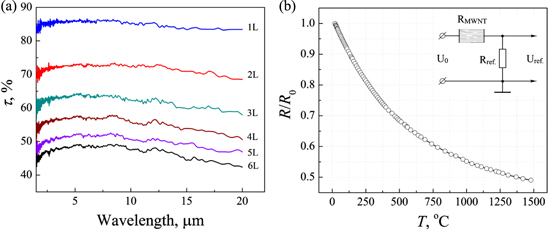
Figure 2. (a) The IR transmittance spectra for non-polarized incident light of MWNT sheets containing different numbers of superimposed sheet layers. MWNT sheets were drawn from a 200 μm high, CVD- grown forest. (b) The temperature dependence of normalized resistance of a non-densified, single layer MWNT sheet attached to the back side of a 25 × 25 mm2 Al2O3 ceramic heater. The temperature of the ceramic plate was measured using an attached K-type chromel-alumel thermocouple. The inset shows the electrical circuit diagram used to measure the temperature-dependent resistance R (T) of the free-standing MWNT sheet as a function of input power Ph and resulting temperature.
Download figure:
Standard image High-resolution imageThe calibration curve shown in figure 2(b) was used in this study for comparative measurements of the temperature of free-standing MWNT sheets. The normalized R/R0 plot was averaged for three consecutive measurements of an MWNT sheet attached to the surface of a ceramic heater in high vacuum (<0.1 mTorr) [8]. This curve has been tested for over 100 forest-derived samples made by CVD with acetylene gas [1] during the past eight years, including individual MWNTs and bundles of MWNTs, extracted directly from the side of a forest, and single and multilayered MWNT sheets and yarns. The measured temperature coefficients of resistance at different temperature regions (the room temperature TCR = (ΔR/R0)/ΔT = −7.6 × 10⁻⁴ K−1, where R0 is the resistance at 295 K) for all of these measured samples were surprisingly similar and invariant of forest height, sheet dimension, and number of superimposed layers. The reason for this consistency in the TCR for nanotubes from different preparations is that the TCR is determined by the concentration of defects in the conduction channels of individual nanotubes [10], and only a very narrow range of CNT growth conditions enables forest spinnability [1].
For free-standing CNT sheets containing differing numbers of sheet layers, figures 3(a)–(e) compare plots of temperature versus applied power from resistance measurements (solid circles), using the figure 2(b) calibration curve, with those obtained optically using the IR camera MobIR (open circles with dashed lines for differing assumed sample emissivities from 0.1 to 0.8). By selecting the sample emissivity that provides a match between the optically determined power dependence of sample temperature and that determined by resistance measurements, good agreement is obtained between the layer number dependence of this emissivity and that derived from the measured IR absorption coefficient at room temperature in air (table 1 and figure 3(f)). Hence, the temperature of a free-standing CNT sheet can be reliably obtained by remote measurement of IR emission using the emissivity derived from optical absorption measurements. At least for the present MWNT aerogel sheet, the visible transmittance at 550 nm (averaged for vertically and horizontally polarized light or measured using non-polarized light), is nearly the same as that for the 1–20 μm wavelength range for sheets containing various number of sheet layers. Hence, one can use visible transmittance to evaluate the needed IR emissivity of MWNT aerogel sheets. The IR thermometry method is preferable for visualization of the temperature profile along the sheet, or to measure possibly different rates of temperature evolution for different areas of the aerogel sheet. However, for MWNT sheets encapsulated between two plates with unknown IR absorption, temperature measurement by the resistance change method provides more reliable data. Though the resistance change method captures the averaged resistance along the sheet, it can be used to measure and control in situ fast dynamic changes of temperature.

Figure 3. (a)–(e) MWNT sheet temperature measured using the MobIR IR camera by assuming sample emissivities between 0.1 and 0.8 (open circles) and calculated from the temperature change of MWNT sheet resistance (solid circles), as a function of applied ac power, f = 1 kHz. (f) Comparison of IR absorptivity α = 1−τ (for sheets containing from one to six sheet layers, averaged for 3–5 μm wavelengths) with emissivities ε derived from comparison of temperatures measured using the resistance change method and those derived (for different assumed emissivities) from IR radiation emission measurements using the MobIR IR camera. Dashed and solid lines are guides for the eye.
Download figure:
Standard image High-resolution imageTable 1. Emissivity of MWNT sheets with different numbers of layers (extracted from figure 3 by comparison of IR thermometer temperature data with data from the resistance change method) is compared with IR absorptivity, α calculated from the average transmittance τ.
| Number of layers | Emissivity, ε | Transmittance, τ, %, (λ = 3–5 μm) | τaveraged, % | Absorptivity, α = 1−τ |
|---|---|---|---|---|
| 1 | 0.16 | 85 | 85 | 0.15 |
| 2 | 0.3 | 71.5–72.7 | 72 | 0.28 |
| 3 | 0.4 | 61–63 | 62 | 0.38 |
| 4 | 0.47 | 55–56 | 55 | 0.45 |
| 5 | — | 50–52 | 51 | 0.49 |
| 6 | 0.55 | 47.5–48.5 | 48 | 0.52 |
Figure 4 presents an example of thermal imaging of an encapsulated TA projector without any emissivity adjustment (ε = 0.8). The 3D temperature profile in figure 4(a) and a 2D cross section of the temperature profile in figure 4(b) captured through the central line for different power levels are taken over the TA device shown in the inset to figure 1(a). The thermal imaging was conducted using a ThermaCAM SC640 (FLIR Systems Inc.). The temperature profile along the central line refers each region to the actual device shown in the top inset. There is a clear distinction between the temperature profiles across each of the three different layering segments, despite the impact of temperature smoothening by absorption of the glass plate and its thermal conductivity. For example, for 10 W input power, distributed as 1.67, 3.33, and 5 W between the strips (see dark yellow triangles in figure 4(b)), the thermocamera yields ∼40, ∼60, and ∼80 °C, respectively. In fact, the temperatures for all three strips (as measured by R/R0 and adjusted emissivities: 0.16, 0.3, and 0.4) are very close: ∼127 °C for 1.67 W of input power for the one layer strip (figure 3(a)), 123 °C for 3.33 W of input power for the two layer strip (figure 3(b)), and 125 °C for 5 W of input power for the three layer strip (figure 3(c)). Thus, emissivity adjustment for each MWNT assembly is crucial for remote temperature measurement.
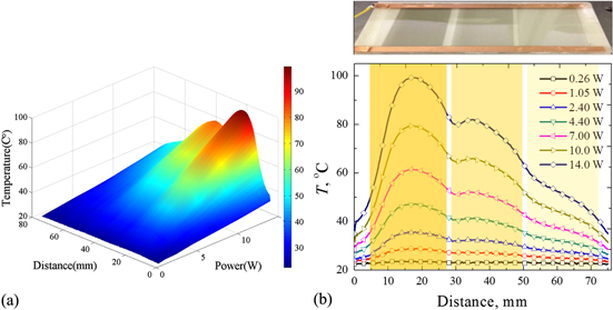
Figure 4. Experimental results on the thermal characterization of the TA device comprising three separated, equal length segments attached to the same voltage input electrodes, which contain (from left to right) three, two, and one stacked forest-drawn CNT sheets. (a) Summary of the temperature as a function of distance across the device array for different levels of total input power. (b) Temperature profile through the central line of the TA device for different total power input levels. Inset on the top shows the TA device of figure 1(a).
Download figure:
Standard image High-resolution image2.2. Power density
To estimate the maximum power density and the range of current levels that the suspended MWNT sheet stack can withstand when it contains various numbers of superimposed layers, we gradually increased the applied ac voltage across the sheet until the sample was destroyed. We recorded the temperature, ac power (f = 1 kHz), root mean square (rms) values of voltage and current, and recorded pictures for more than 50 samples placed in a high vacuum or an argon gas environment. As an example, figure 5 shows the response of a 1 × 3.2 cm2 MWNT sheet attached to 2 mm thick copper electrodes to the increasing applied ac power and resulting black-body radiation in a vacuum. The attachment was performed by densification of the MWNT sheet on the outer sides of the copper rods using a volatile liquid (methanol) for wetting, followed by quick drying. This densification method provides robust electrical connections through van der Waals forces and is especially important for high-temperature applications where many metallic interconnects do not work. Voltages were applied along the sheet width direction, which is the direction of nanotube alignment.

Figure 5. The gradually increased ac power, shown at the bottom of each picture, resistively heats up the CNT sheet (1 × 3.2 cm2) and generates increased black-body radiation. The temperatures of the MWNT sheet are shown on the top right corner of each picture. The progressively darker background indicates the automatic reduction of the camera's sensitivity as the radiation becomes brighter: f = 1 kHz, R0 = 378 Ω (∼1210 Ω sq.−1). The first five temperature samplings were made using the recorded resistance change compared with the calibration curve of figure 2(b). The next two were measured using a PR-650 SpectraScan colorimeter (PhotoResearch Inc.). The last picture panel shows the ruptured sheet that results from further increase in input power.
Download figure:
Standard image High-resolution imageThe maximum input power density obtained in a vacuum (<0.1 mTorr) for a given interelectrode separation distance of 1 cm was 22 W cm−2. Further increasing the applied power dramatically increases the resistance of the sample (controlled by a voltage bias on a series-connected 2.5 Ω reference resistor) and a break progressively appears in the sheet along a line perpendicular to the direction of sheet alignment. Apparently, in the obtained vacuum of <0.1 mTorr, there are still a sufficient number of oxygen molecules to eventually lead to burning the CNTs. Damage starts at the location of some defect or where the local temperature is highest (in a vacuum, the hottest areas usually are at the center of the sheet). As soon as a break (burned hole) appears, the current redistributes to neighboring channels, forcing them to overload and break when constant input power is maintained. A small flash spot can be seen that immediately propagates perpendicular to the sheet alignment in both directions and eventually disconnects the entire circuit, as shown in the last panel of figure 5.
In argon gas atmosphere, the useable input power density is higher, Pmax = 28 W cm−2, due to the additional heat dissipation channels through direct thermal conduction to the gas. The free convection of heated gas (vertical flow of hot gas) significantly alters heat distribution across the sheet area. The top part of a vertically fixed MWNT sheet in large chambers was always much hotter than the bottom part, inducing much earlier thermal breakage, which usually started at the central uppermost point and continued downward. A horizontally fixed MWNT sheet in a large argon chamber experienced strong vertical gas flow perpendicular to the sheet orientation and induced sheet flapping, which increased the bundling of nanotubes into larger diameter fibers. The effect of convection can be mitigated by reducing the volume of the enclosure and partitioning the heater into small sections.
The obtained power density per square sheet divided by the averaged number of aligned individual MWNTs (∼384 600 tubes per one cm width) suggests a much lower breakdown current (Ivac ∼ 0.52 μA) than found for a single MWNT tube (9.5 nm in diameter) directly attached to the metallic electrodes, I ∼ 175 μA or 19 μA per shell (L < 200 nm) [11]. The idealized picture of single-tube channels obtained from atomic force microscopy areal analyses of a densified highly aligned MWNT sheet shows that the average separation distance between 10 nm tubes is 26 nm, which is consistent with the observed transparency of the sheet. Despite a low breakdown current, the average resistance of an individual tube of 46.5 kΩ μm−1 is independent of the sheet length in the nanotube orientation direction (the current flow direction), and consistent with results for other CVD-grown MWNTs [12]. The high thermal conductance of short individual tubes used in [11] (taking aside the resistively created heat) assists in realizing the high breakdown current level. The macroscopic distance between electrodes and high aspect ratio of individual tubes (∼35 000) in studied sheets make the contribution of thermal conductivity along the sheet negligible. Apparently, the strong tube–tube interconnects having only slightly higher resistance in highly aligned MWNT sheets [13] and the correspondingly higher temperature might have little contribution to this lowering of the current limit.
The shorter the distance between electrodes (along the nanotube alignment direction), the higher the power density that the MWNT sheet can withstand. For example, a single 2 × 18 cm2 MWNT sheet in argon gas could withstand only ∼10 W cm−2, whereas a small 2 × 2 mm2 multilayered (five layers) sheet could withstand ∼300 W cm−2. However, the temperature modulation (important for TA sound generation) on the sheet surface of short length samples (L < 2 mm, [14]) is much lower due to the direct heat dissipation along the CNTs to the copper electrodes.
The residual oxygen (4–10 ppm) in the argon glove box or in the vacuum chamber filled with ultra-high-purity gas is the main limiting factor for achieving a high power density. Due to the large surface area of the aerogel MWNT sheet, there is a strong interaction with residual oxygen (based on six samples tested in the argon glove box). Oxidation in the argon glove box increases the sheet resistance at T = 650 °C at a rate of 20% per hour, which eventually destroys the sample. An increase in the number of superimposed layers increases the allowable power density. However, heat accumulation inside of a stacked sheet assembly makes the dependence of maximum allowable power density on number of stacked sheets nonlinear. Stable operation of the sound projector in air and argon gas was achieved at MWNT sheet temperatures below 600 °C, with the highest realized stable power density of 5 W cm−2 (f = 1 kHz). The use of getter coating on the inner surface of encapsulated TA devices, which captures residual oxygen, might increase the stable operation temperatures. Note that the low exposed surface area of twisted MWNT yarns (ρ = 0.8–1 g cm−3) makes their operation in 0.1 mTorr vacuum, or high-purity argon, much longer (several days at T = 2000 °C).
The visual inhomogeneity of spectral temperatures (see the picture in figure 5 with T = 1200 °C) results in deviation of the power-temperature dependence P(T) from the Stefan–Boltzmann law: P = AεσT4. Assuming that, in a vacuum, the applied ac power (rms value) is totally transferred to black-body radiation, the upper limits of observed temperatures are higher than estimated from the power increase. Due to the negative temperature dependence of resistivity in CVD-grown MWNTs, current redistribution toward larger bundles with higher temperature (hence, lower resistance) is reinforced at higher power and increases the inhomogeneity. Apparently, due to the higher radiation power of high-temperature spots (bundles4 and interconnects), the spectrometer picks up the temperature of those spots, whereas the average temperature is much lower (by ∼10% relative to ambient temperature).
2.3. Thermal management of resistively heated free-standing MWNT sheets
The pressure variation prms of an open-to-air TA projector increases linearly with increased applied power Ph [4]:
Unlike other sound generation techniques (coil loudspeakers, piezoelectric, magnetostrictive, and electromechanical transducers), the efficiency of TA transducers η is also proportional to the applied power:

Indeed, because the TA loudspeaker acts as a heat engine, the maximum energy conversion efficiency, according to Carnot's theorem, cannot exceed η = 1 − Tc/Th, where Tc is the absolute temperature of the cold reservoir and Th is the temperature of the hot reservoir. Therefore, high applied power, which implies a high temperature gradient, is a preferable working regime for TA transducers. For Tc = 295 K and Th = 373 K, the Carnot's efficiency limit is 20%. CNTs oxidize above ∼820 K in air (for pristine 10 nm MWNTs [15]), thereby limiting the maximum Carnot's efficiency in air to ∼60%.
In inert gases, like ultra-high-purity argon, we have shown that a single MWNT sheet can withstand a temperature of 2300 K with a power density of 28 W cm−2, which can provide a substantially increased Carnot's efficiency of η = 85%. However, the heat dissipation from the interior of encapsulated devices becomes a substantial obstacle for high-power TA projectors, which we address here via structural modification of the CNT sheet assemblies and thermal management of the TA sound projectors.
2.3.1. High-voltage input
One method to increase the power density of a TA projector is to directly increase the temperature variation of the resistively heated single MWNT sheet by increasing the applied ac voltage. Because the average sheet resistance of the single MWNT sheet is relatively high, ∼1 kΩ sq.−1, a high ac voltage is required. However, voltages above 300 V create strong lateral electrostatic actuation of a relatively long (>2 cm), highly aligned sheet [16], which eventually bundles the MWNTs into large ropes and deteriorates the performance of the device. Another drawback is that high voltage amplifiers require special precautions and insulation, especially for underwater use. In addition, a high input impedance is not suitable for many electronic applications.
2.3.2. Stacking of MWNT sheets
The resistance of a TA heater, and consequently, the applied voltage, can be reduced by parallel stacking multiple layers directly on top of each other or through spacers (figure 6(a)). The direct stacking of aerogel density MWNT sheets one over another increases the conductivity of the assembly, which is proportional to the number of layers nL. Assuming the heat transfer coefficient β is constant for low nL, the temperature gradient ΔT = (T–T0) created by a double-layered (2L) assembly at a fixed applied power should be two-fold lower. Indeed, at low power, a 2L assembly in figure 6(b) shows almost half the temperature gradient of a single layer when the same total power is applied in ambient air. However, this tendency for the measured sheet temperature is quickly saturated with further increase of nL. The non-linear increase of temperature versus applied ac power in figure 6(b) results from the non-linear thermal conductivity behavior of air (κ ∼ (T/M)1/2 for monatomic gases with molar weight M), which is enhanced at high power by black-body radiation.

Figure 6. (a) Schematic diagram of stacked MWNT sheets. (b) The average temperature on the surface of a multilayered sheet estimated using the resistance change method. The inset shows a picture of six superimposed MWNT sheet layers suspended between two copper electrodes. (c) Sound pressure prms versus applied ac power Ph for increasing numbers of superimposed MWNT sheets. The theoretical line predicted by equation (1) is shown by the dashed line. (d) The average temperature TR/R(0) versus applied ac voltage Uh for various numbers of superimposed layers. (e) Sound pressure versus applied ac power for increasing numbers of MWNT layers placed a distance of 1 mm from each other. (f) The average temperature versus applied ac voltage for increased numbers of MWNT layers placed a distance of 1 mm from each other. (g), (h) are the same as (e), (f) respectively, but are a 3 mm spacing between layers. The inset to figure 6(g) is a picture of the expanded assembly with 3 mm spacing. All of the measurements of figure 6 were conducted in ambient air.
Download figure:
Standard image High-resolution imageFor the case of a specific heat capacity of air, Cp = 1006 J kg−1 · K, f = 3 kHz, and a distance from the microphone of 3 cm, the pressure variation slope, prms = 0.117 Pa W−1, obtained using equation (1) (shown by a dashed line in figures 6(c), (e), (g)) is consistent with the prms(Ph) slope measured for the single MWNT layer. The stacking of contacting sheets decreases gas access to the inner layers (reduces the heat transfer coefficient β) and at increased power, creates an accumulation of heat interior to the stack, which produces an undesired increase in static background temperature T0 (the right side upward swing of temperature at high input power in figure 6(d)) and a corresponding decrease of the prms(Ph) slope in figure 6(c).
2.3.3. Spacing between stacked MWNT sheets
To avoid heat accumulation between parallel layers, the spacing h between separate layers must be larger than the thermal diffusion length l = (2α/ω)1/2, i.e. h > (α/πf)1/2. Here, α is the thermal diffusivity of air (22 mm2 s−1), f is the sound frequency, and h is the layer separation distance in figure 6(a). Assuming the sound spectra spans from 20 Hz to 20 kHz, the minimal distance between layers at f = 20 Hz in air must be h > 0.59 mm. On the other hand, to avoid requiring a phase delay between the front and rear layers for a high-fidelity sound source, the total thickness of the stack should not exceed a tenth of the sound wavelength, L < λ/10. In this case, for 20 kHz, L should be less than 1.7 mm. Hence, to obtain an 8 Ω input impedance by stacking free-standing MWNT sheets (R1L ∼ 1000 Ω sq.−1), one must sacrifice either the sound spectra range or the energy conversion efficiency.
For an expanded assembly of parallel MWNT layers, the power increases with each next attached layer, but the temperature of each sheet at a fixed voltage should not depend upon the number of layers. Each additional parallel layer conducts the same current and reaches the same temperature. Indeed, the temperature curves for 3 mm separated layers in figure 6(h) all overlay on a single curve.
Separating MWNT sheets 1 mm from each other substantially narrowed the prms(Ph) distribution (figure 6(e)). However, the average temperature of the whole stack still increases for an increasing number of layers and reaches 282 °C for six parallel layers (figure 6(f)) at an applied voltage of 100 V (the overheating partially resulted from limited air convection through used 1 mm thick Plexiglas frames). A further increase in spacing to 3 mm increases the sound pressure and makes the temperature of the stack independent of the number of sheets (figure 6(h)). The average temperature at a maximum applied voltage of 100 V is reduced to 190 °C. Thus, the temperature difference between a single layer (or a six layer expanded structure) and six superimposed layer structure (figure 6(d)) is ΔT = 380 − 190 = 190 °C, indicating that half of the applied heat energy ΔQ = (Cp sheet·msheet + Cp gas·mgas)·(ΔTac + ΔTdc) is lost as an accumulated background dc temperature. Here, Cp and m are the specific heat capacity and the masses of the heater and surrounding gas, respectively. This heat power loss, together with the reduced variable temperature caused by an elevated temperature background T0 = Troom + ΔTdc, is consistent with the decrease in acoustic power, ∼p2rms, for the six superimposed layer structure (figure 6(c)).
2.3.4. Interdigitated electrodes
Another solution for the issue of high resistance and reduced heat dissipation from the interior of the encapsulated TA projector is the use of narrow parallel strips of single (or few) layer MWNT sheets using interdigitated electrodes, as shown in figure 7(a). The proper choice of electrode–electrode distances reduces the input impedance to the desired value and can improve the heat dissipation conditions by increasing the direct heat conductance through the MWNT sheet to the electrodes. The pure ohmic input electrical impedance of a flexible TA projector, shown in figure 7(a), is 30 Ω, and for the TA projector shown in figure 7(b) is 33 Ω.

Figure 7. (a) Flexible TA transducer using interdigitated electrodes patterned on 160 μm thin 5 × 5 cm2 printed circuit board plates. (b) TA projector comprising two layers of MWNT sheets attached to interdigitated electrodes is encapsulated in argon gas between AlN ceramic plate (7.6 × 6.6 cm2, 250 μm thick) and aluminum heat sink.
Download figure:
Standard image High-resolution image
2.3.5. Enhanced heat dissipation
Using a high-surface-area metallic back-plate, which enhances heat dissipation, can substantially increase the power density and efficiency of the TA projector. The argon-gas-filled TA projector shown in figure 7(b), with a deep-grinded top surface of aluminum radiator, demonstrates 2% efficiency in air and 10% underwater at an input power density of 7 W cm−2. The 7.6 × 6.6 cm2 AlN ceramic plate which is 250 μm thick can withstand >1000 °C. High thermal conductivity of the plate (170 W mK−1) is especially important for cooling the interior gas in underwater applications. The sound pressure level at f = 1.5 kHz, measured in an anechoic room at a distance of 1 m, was 115 dB re 20 μPa.
3. Conclusions
The proper thermal management of devices using nanomaterials needs a new approach for correct estimation of the thermodynamic parameters of the system. We studied the heat dissipation processes from the interior of TA projectors using encapsulated, multilayered, free-standing, aerogel CNT sheets. Because the direct contact measurement of the temperature of free-standing CNTs is impossible, due to the nanoscale thicknesses of these sheets, we established a very precise and reliable temperature measurement technique. This technique combines measurements of the comparative resistance change for the free-standing MWNT sheet (assuming the same temperature coefficient of resistivity for supported and free-standing MWNT sheets) and optical transmission measurements to extract the needed emissivity ε and finally obtain the correct temperature by remote IR sensing.
We experimentally obtained the highest power density applicable to the CNT sheet in a vacuum and in argon gas. The breakdown current of the aerogel sheet with nanoscale diameter of individual CNTs is extremely sensitive to residual oxygen. In commercially available vacuum systems with pressure 0.1 mTorr and ultra-high-purity argon gas, the 1 cm wide single layer MWNT sheet (the diameter of individual nanotubes is 10 nm) withstands 22 and 28 W cm−2 input electrical powers, respectively. The same sheet twisted into bulk yarn can withstand a much higher temperature and demonstrates two orders of magnitude longer lifetime under the same conditions.
A multilayered assembly of many MWNT sheets directly superimposed onto each other loses the advantages of the aerogel structure and becomes thermally inertial when the number of stacked sheets is large. The efficiency of TA sound generation is thereby reduced. Spacing of superimposed layers by distances greater than the thermal diffusion length substantially reduces the heat accumulation and makes the sound pressure a linear function of applied power.
The use of interdigitated electrodes reduces the input electrical impedance to desired values. Use of a back-plate with proper spacing of the interdigitated electrodes and enhanced heat dissipation ability substantially improves the energy conversion efficiency of encapsulated TA projectors to 2% in air and 10% underwater.
Acknowledgments
We thank Xavier Norberto Lepró Chávez (NanoTech Institute, UT Dallas) for providing drawable MWNT forests. This research work was supported by US Office of Naval Research grants N00014-14-1-0152 and N00014-13-1-0180, Air Force Office of Scientific Research grant FA9550-12-1-0211, and the Robert A. Welch Foundation Grant AT-0029.
Footnotes
- 4
The bundling (which initially appears in as-grown MWNT forest, then increases during dry-state draw of the sheet) increases in a single layer MWNT sheet during testing. This bundling is enhanced by (i) vibrations of nanotube chains electrostatically generated by the high applied ac field (the vibrations of bundles, especially at the edges, are visible by naked eyes at applied voltage >100 V), (ii) Lorenz forces at high applied currents, and (iii) gas convection if the chamber is large. Certainly, after reaching some bundling level, the sheet structure under tension remains essentially constant. By stacking layers under slightly tilted angles (5–10 degrees), we can substantially reinforce the assembly and, to some extent, prevent further bundling (if the sheet stack is under tension).