

Abstract
Nonchemical flame control using acoustic waves from a subwoofer and a lightweight carbon nanotube thermoacoustic projector was demonstrated. The intent was to manipulate flame intensity, direction and propagation. The mechanisms of flame suppression using low frequency acoustic waves were discussed. Laminar flame control and extinction were achieved using a thermoacoustic 'butterfly' projector based on freestanding carbon nanotube sheets.
Export citation and abstract BibTeX RIS
Flame extinction using sound waves has been known for over 150 years [1, 2]. However, the suppression mechanisms are not yet well understood. Previous efforts have demonstrated that a flame can be extinguished by low frequency acoustic waves [3, 4], and flame suppression is enhanced in microgravity [5, 6]. Studies investigating air cooling flame extinction, based on the ideal gas-law, are unavailable. We here report flame suppression using engineered acoustic waves. Our results show that the ideal gas law provides insights into the acoustic flame suppression mechanism, where pressure perturbations cause flame stretching and fluctuations in boundary-layer temperatures. These studies are extended from a subwoofer to lightweight thermoacoustic (TA) projectors based on freestanding carbon nanotube sheets in a butterfly device.
Advances in acoustic flame suppression will eventually provide a practical alternative to conventional fire extinguishers in confined places and aerospace environments. Lightweight, low-frequency carbon-nanotube TA sound projectors having a novel butterfly structure were constructed and characterized for weight-sensitive applications. Flame suppression outdoors, which may require high power acoustic waves and tuning algorithms for optimal wave projection, is beyond the scope of this study.
We will first describe and analyze experimental results on flame suppression and flame extinction using a subwoofer and thereafter analyze these results. We address this work to novel carbon nanotube thermoacoustic sound projector that powers on larger scales a butterfly-configured sound projector.
A 150 W powered subwoofer (Klipsch R-10 SW, shown in figure S1 (stacks.iop.org/JPhysD/50/29LT01/mmedia) of supplementary materials (SM)) was utilized to study the mechanisms of acoustic flame suppression. At a frequency range of 21–26 Hz, the laminar flame of a wax candle releasing ~32 W of heat (see combustion properties in table S4) was extinguished at a distance of 1.0 m from the subwoofer using only 2 Pa root-mean-square sound pressure (prms), which corresponds to a 100 dB sound pressure level (SPL). When the flame source diameter was increased by 8 mm (from 1 mm), the laminar flame survived up to ~18 Pa (SPL ~ 119 dB), implying a nearly linear increase of prms with wick diameter. However, at the same one-meter distance and frequency range, extinction of ethanol fuel burning in a 10 cm diameter Petri-dish was achieved at a lower SPL, ~95 dB, suggesting a lower coupling between the flame and the fuel source [7, 8]. The maximum distance between the candle and the subwoofer to realize flame extinction was ~2.0 m.
For a maximum SPL ~108.3 dB for this particular subwoofer (measured at r = 1 m from the source and 51 Hz peak frequency) the pure sound waves from the subwoofer front side were insufficient to extinguish the flame. However, acoustic flame extinction was achieved using sound emitted from the rear duct (a bass reflex enclosure is shown in figure S1(b)). This port had a smaller diameter,  = 8 cm, than the front cone (
 = 21 cm). At the highest disruptive frequency (~22 Hz), the average sound pressure measured in the rear duct side at 1 m was ~40 times higher than at the front cone, and the sound beam was more directional. The narrow duct generated high enough periodic air perturbations (spikes) causing the sound beam to become turbulent, which increased flame instability. Spike-like signals superimposed on the smooth sound wave were observed in the acoustic pressure measurements shown in figure 1. The results were collected using a microphone (ACO Pacific model 7046, 2 Hz–20 kHz, Sensitivity = 54.3 mV Pa−1) placed ~3 cm behind the candle flame. Close examination of the peak locations (figure S5 in SM) shows synchronization with background sound waves, where the SPL exceeded 130 dB. At a reduced SPL, the results show a correlation between the acoustic spikes and flame disruptions, which leads us to believe that the spikes caused the flame extinction.
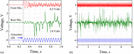
Figure 1. The applied voltage (f = 22 Hz) and sound responses of the subwoofer (a) at the sound beam front and (b) during continuous operation recorded by digital oscilloscope Tektronix DPO4104B-L. Switching ON the high power amplifier (blue arrow) initiated sound propagation at the front cone and rear duct. At 1 m distance from the front cone and rear duct the sound pressure signals arrived after ~7 ms (top red-line channel) and ~11 ms (middle green-line channel), respectively. The first turbulent burst appeared at ~220 ms. (b) Sound pressure spikes from the rear duct (middle green line) on a slow oscilloscope scan. The peak-to-peak amplitude of the spikes was 5.8 V, corresponding to pp–p = 106.8 Pa (SPL = 134 dB).
Download figure:
Standard image High-resolution imageAt the subwoofer resonance (fr ~ 22 Hz), the maximum cone displacement reached ~13 mm (twice the subwoofer displacement at f = 51 Hz), thereby providing the maximum SPL (108.3 dB, prms = 5.2 Pa, r = 1 m). The air movement from the rear duct became turbulent at the resonance, producing ~4.7 m s−1 air velocity in the rear duct, which was  21/
21/ 8 times higher than the air velocity at the front cone (u = dx/dt = ωxosin(ωt) = 1.8 m s−1, where ω = 2πf). The Reynolds number was, Re = ud/ν = 240 00, where u is the air velocity in a d =
  8 cm duct, and ν = 1.57 × 10⁻⁵ m2 s−1 is the kinematic viscosity of air. At SPL = 138 dB (165 Pa) inside the duct, the first spikes were observed 0.5 m away from the duct opening, (u = 0.4 m s−1 and Re ~ 2100, which is near the critical Re = 2200 for turbulent transition in round tubes [9]).
The flame suppression dynamics for two candle arrays are shown in figure 2: aligned parallel (a)–(c) and perpendicular (d)–(f) to the acoustic beam. Figures 2(a) and (d) show the flames prior to acoustic excitation. The transition time to develop full magnitude sound at f = 22 Hz was ~0.23 s. Figures 2(b) and (c) show the consecutive images of acoustic flame suppression after ~1.0 s and ~2.0 s of acoustic excitation, respectively (sampling rate ~4.5 images s−1). The turbulence development began at the end of characteristic transition time, which includes the amplifier transition time (<2 ms), the speaker diaphragm inertia at its mechanical resonance (Δτ = Q/f ≈ 0.2 s), and the acoustical front travel time (~3 ms). For perpendicular alignment, the first turbulent gust extinguished the three middle candles after ~1.0 s, (figure 2(e)). The next dollop of acoustic spikes extinguished an additional candle after ~2.0 s (figure 2(f)). The arrival of a ~40 cm diameter acoustic beam is indicated by the fringes rustling (dashed yellow line in figure 2(f)).

Figure 2. Extinction of candle flames by a turbulent acoustic wave at f = 22 Hz and SPL = 134 dB. (a)–(c) Array of candles aligned along the acoustic beam. The distance from back-side duct opening to the first candle is 1 m and the inter-candle separation is 10 cm. (d)–(f) Array of candles aligned perpendicular to the acoustic beam. A light, 10 cm-long nylon yarn fringe, attached to the horizontal candle support bar, visualizes the beam cross-section and the dynamics of air flow. The distance from sound source to the candle support bar is 1 m (see setup schematic diagram in S3.1).
Download figure:
Standard image High-resolution imageTo understand the flame extinction mechanism, we first examined the temperature modulation magnitude of candle flame, ΔT, due to single-tone sound wave propagating at low frequencies in adiabatic conditions. According to the ideal gas law, the pressure increases or decreases the temperature in dense or rarefied mediums, respectively [10]:
where, γ = Cp/Cv = 1.41 is the heat capacity ratio of air, T0 ≈ 1000 °C (1273 K) is the average temperature of the candle plume measured using a FLIR T650SC infrared (IR) camera and K-type thermocouple, and P0 = 101 325 Pa is the ambient pressure. The peak-to-peak sound pressure achieved at r = 1 m and f = 51 Hz was Δp = 14.6 Pa. The maximum temperature modulation amplitude, according to equation (1), could not exceed ΔT = 0.053 °C. The flame temperature modulation measured by an IR detector PDA10PT (ThorLabs Inc.) was ΔT = 2.4 °C. The IR detector response at a given distance, angle, and aperture was calibrated using the intensity of incident light from the candle flame modulated by a rotating optical chopper f = 51 Hz (figure 3(a)). At 1000 °C, the peak-to-peak signal was Up–p = 1700 mV (pink signal in figure 3(b)). The sound induced (Δp = 14.6 Pa) temperature modulation of the flame produced Up–p = 23 mV IR light intensity modulation (pink signal in figure 3(c), measured using a SR830 lock-in amplifier).

Figure 3. (a) An amplified IR detector PDA10PT (ThorLabs Inc.) was used to measure the variation in incident light intensity modulated by a chopper (b) and sound wave (c), shown in pink color. The yellow channel of oscilloscope in panel (b) and (c) displays the sound pressure at candle location measured using precision microphone model 7046 (ACO Pacific). The blue channel is the sinusoidal voltage applied to subwoofer. The wavelength of IR detector, which has a wide signal modulation bandwidth from DC to 1.6 MHz, is 1–5.8 µm. The middle inset shows the flame shape at increased SPL.
Download figure:
Standard image High-resolution imageUsing the Wien approximation of blackbody radiation at low temperatures (hc/λ  kbT, λT ~ 0.006 m·K; here h is the Planck constant, c is the speed of light in a vacuum, λ is the wavelength of the electro-magnetic radiation (of the detector), kb is the Boltzmann constant and T is the absolute temperature) [11],
and the above calibration (Iλ=4.9 µm ≈ 1700 mV ∝ T = 1000 °C), the temperature modulation magnitude becomes ΔT = 2.4 °C, which is ~45 times higher than the estimated ΔT = 0.053 °C.
The observed discrepancy might be a result of additional acoustic-flame interaction mechanisms. The oxygen molecules are denser in high pressure regions of sound waves, which enhances the fuel oxidation rate compared with that in the rarefied areas. Since the oxidation rate exponentially depends on the concentration of involved molecules, this effect may significantly increase the flame ΔT. More specifically the burning rate of laminar flame driven by convective heat is determined by combustion kinetic coefficient k = B ⋅ exp(−ΔHc/RT), where −ΔHc is the combustion reaction enthalpy (which linearly depends on the fuel/oxygen stoichiometric ratio), and R is the gas constant [12].
Even when considering the pressure spikes, which are ~40 times larger than the acoustic waves, the theoretical temperature modulation is approximately ~40 × 2.4 °C ≈ ±48 °C. Understandably, the instantaneous temperature decrease during the rarefaction period facilitates flame extinction, but is not the main extinction mechanism. To suppress the combustion reaction, the fuel temperature must be below the autoignition temperature, which is ~200 °C for candle wax, and varies for different fuels: gasoline—280 °C, ethanol—365 °C, pine wood—427 °C, and propane—470 °C. Hence, an additional ~50 dB (total SPL = 158 dB) is needed to cool the flame from 1000 °C to 200 °C.
The above considerations ignore the displacement of fluid particles in propagating sound wave, which is substantial at low frequencies. The periodic displacement of the flame from its fuel source (i.e. from the wick location) is another enhancing mechanism for temperature modulation. Displacement from the combustion region reduces the temperature at the source location by introducing a cold region of air. The new cold air enriches the fuel with oxygen, which is often been used to accelerate the combustion rate (acoustic perturbation of non-premixed diffusion flame) [13–17]. However, at high air displacement the flame separation from the fuel can reduce the wick temperature and suppress the combustion reaction. For high SPL (>120 dB) this mechanism was a major contributor to flame extinction. For the above experiments, using f = 51 Hz, and Δp = 14.6 Pa (at 1 m distance), the flame displacement did not exceed 0.11 mm.
Therefore, the displacement mechanism can be neglected (p = ρυsu = ρυsωx, x = 0.11 mm, where ρυs ≈ 400 kg m−2 s is the acoustical impedance of air, ω and u as designated above). Decreasing the distance to the candle, thereby increasing the SPL at the flame resulted in the flame splitting pictured in the middle column inset to figure 3(a), which shows ~2 mm splitting of the candle flame at f = 51 Hz when the distance between the cone diaphragm and candle was reduced to 0.25 m (SPL = 115 dB). Further increase in SPL increased the flame displacement and resulted in flame stretching. The temperature of the stretched flame measured at the candle wick decreased from ~1000 °C to ~870 °C (see S2 in SM), but was not enough to extinguish the flame. Flame extinction was achieved in the low frequency region (21–26 Hz) corresponding to the subwoofer resonance, when flame displacement supported with 40-fold turbulent bursts was significant.
Further information on the displacement mechanism of flame extinction was obtained by increasing the diameter of the wick. By twisting multiple wicks, we prepared five candles with wick diameters 0.8, 1, 2, 4 and 8 mm, respectively. The sound pressure (and corresponding flame displacement) required for flame extinction is expected to be higher for the higher diameter wicks. The results in figure 4 show, if fact, that the averaged turbulent sound pressure required for flame extinction is proportional to wick diameter. This result indicates that extinction of a diffusive flame occurs when the flame is displaced sufficiently away from its fuel source, x ⩾ D/2, D is the plume diameter. On the other hand, the flame excursion time should be long enough to cool the source temperature below the autoignition temperature, which requires low frequencies. This observation is consistent with the increase of displacement required for acoustic flame extinction that has been previously observed for an acoustic field orthogonally interacting with a droplet stream flame consisting of different droplet sizes [3].

Figure 4. The extinction sound pressure measured at f = 22 Hz for increasing diameter candle wicks. The right axis shows the displacement calculated from averaged sound pressure measured at 1 m from the rear duct. The wicks heights were ~1.5 cm, except for the 0.8 mm diameter wick, which was 1 cm high. The insets show the flame of 0.8 mm (top) and 4 mm (bottom) wicks. The heights of flames were ~1.5, 1.8, 2.3, 3, 4 cm, respectively, for increasing diameter wicks.
Download figure:
Standard image High-resolution imageThe x ⩾ D/2 requirement for extinction is very simplified picture of acoustic wave interaction with a laminar flame, which neglects the difference of density in flamelet region and ambient, the volume of the flame, and the wave propagation direction. Nevertheless, it gives correct relation between displacement of air particles in acoustic wave x, flame excursion, and the period of the acoustic wave t: x = p/ρυsω = pt/2πρυs. More complicated considerations given by Gor'kov [18] and Tanaba et al [19] involves a buoyancy equation and thermoacoustic streaming.
To achieve high air particle displacement at the flame fuel interface, we have developed a lightweight thermoacoustic (TA) projector that can be used as a flame extinguisher. The TA sound generation mechanics resembles that of a combustion engine, but is powered by an electric current [20–22]. Instead of a gaseous mixture, the encapsulated TA piston chamber is heated resistively by a thin carbon nanotube (CNT) aerogel sheet. The TA projector has two unique properties: (1) the sound spectrum is broad, (2) the efficiency increases with increased temperature gradient (i.e. with applied AC power) [23, 24]. The previously developed encapsulated two-plate TA projectors (comprising a freestanding CNT sheet suspended between two lightweight plates, sealed with silicone) are efficient at f > 200 Hz, which require low amplitudes of plate vibration [25–27]. To generate a SPL above 100 dB at f < 50 Hz, the excursion displacement of the vibrating plate (or cone in the dynamic loudspeaker) must to be >4.6 mm. The need for large displacements requires a large spacing between the vibrating plates and the CNT sheet, which reduces the sound generation efficiency. To increase the plate vibration amplitude, a new single plate 'Butterfly' design was created, where we shifted the TA chamber to a vibration node corresponding to the lowest vibration response. In the butterfly design, shown in figure 5, the vibrating plate is cantilevered from the TA device. Therefore, a higher efficiency was achieved, where the edge displacement was >3 cm, with a small (~0.3 mm) displacement at the active chamber.

Figure 5. (a) Schematic diagram of a single-plate cantilevered TA device. The 'Butterfly' type TA projector in OFF (b) and ON (c) states. The surface area of the aluminum plate is 10.5 × 30.4 cm2 and its thickness is 0.83 mm. The active element is an encapsulated freestanding CNT sheet suspended between the aluminum plate on top and the heat sink on bottom. The spacing between the CNT sheet and the aluminum plate (and sink plate) was 1 mm. The frequency (d) and power (e) dependencies of sound pressure measured at the edge of vibrating aluminum plate for sample #4 (The distance to microphone was 1 cm). The blue solid squares in (b) show the power dependence of excursion displacement.
Download figure:
Standard image High-resolution image
Several 'Butterfly' TA devices were created with different resonance frequencies (20–50 Hz), by manipulating the plate geometries. The 'Butterfly' TA projector shown in figure 5 generated 3.0 Pa sound pressure at fr = 32 Hz (figure 5(d)) with ±14 mm displacement at the edges (figure 5(f)) at an applied AC power of ~25.8 W. The high quality factor (Q = 30) of plate vibration at the resonance frequency enhanced the energy conversion efficiency by the factor Q2 (see equation (17) in [25]). The sound pressure and excursion displacement at the edges were sufficient to extinguish a candle flame placed 5 cm away from the edge of the plate. The flame suppression differed from that which we observed due to turbulent flow produced by the subwoofer. The flame was stretched gradually in ~2 s without strong flame perturbations.
In conclusion, flame suppression by adiabatic cooling using pure sound waves requires a SPL > 158 dB m−1, confirming Lord Rayleigh's prediction: 'Smooth pure sounds are practically without effect unless of very high pitch' [2]. For small laminar flames, the displacement of the flame at low frequencies stretches the flame and reduces its temperature. The low frequency sound waves provide large flame displacement allowing sufficient time to cool the fuel source by supplying colder air. For large-scale fires, short turbulent gusts of sound wave created in narrow tubes can be an efficient acoustic suppression method, but further studies are needed.
Acknowledgments
This work was supported by Office of Naval Research grants N00014-14-1-0152, Army Research Office STTR Contract W911NF-15-P-0023, and Robert A Welch Foundation Grant AT-0029. The authors E Habtour and B Mills at ARL acknowledge funding by Joint Aircraft Survivability Program Office (Project No. JASP-TR-14-05).
Supplementary material
Includes additional pictures, used equipment and tables. This material is available at stacks.iop.org/JPhysD/50/29LT01/mmedia.