
Abstract
A new memristor (MR) emulator is designed by making use of only three current-feedback operational amplifiers, one varactor diode, one capacitor and five resistors. As compared with other reported MR emulators, only three active devices and ten components in total are required for realizing this MR emulator, and hence this emulator can be regarded as a simpler one for the moment. The results obtained by Multisim simulation and experimental prototypes are given to verify the practicality and feasibility of this MR emulator.
Export citation and abstract BibTeX RIS
As a unique two-terminal fundamental circuit element with information storage ability, the memristor (MR) has attracted immense worldwide interest since the researchers at HP labs announced the successful fabrication of nanoscale memristive devices.[1,2] Since then, many MR devices have been designed and manufactured. By inserting a thin A1Oδ barrier layer between the electrode and the tantalum oxide resistive switching layer, triple-layer ReRAM devices with improved resistive switching performance are demonstrated.[3] The analog switching in HfOx-based resistive memory with a thermal enhanced layer is proposed[4] for improving the switching speed and data retention. The nanoscale MR has been used to structure a neuromorphic network with gradual and continuous weight change,[5] and based on which, an integrated neuromorphic network hardware system is built and trained online for grey-scale face classification. The experimental implementation of sparse coding algorithms in a bio-inspired approach using a 32 × 32 crossbar array of analog MRs is reported.[6]
However, since MRs are still not commercially popularized, currently, MR emulators are still necessarily required to uncover the dynamic characteristics of MR-based circuits.[7–12] Many MR emulators have been proposed by making use of active devices and passive circuit components. As discussed in Ref. [7], in addition to fourteen resistors and one capacitor, five operation amplifiers and one JFET transistor are used to structure a ground MR emulator. An analog MR emulator with cubic nonlinearity is designed[8] for establishing the third-order chaotic oscillator circuit, of which three operational amplifiers and two multipliers are used. The light-dependent resistor (LDR) is employed to implement the MR emulator[9] along with three operational amplifiers, two capacitors and nine resistors. However, this MR emulator has the drawback of low accuracy of input current. A hardware circuit for emulating floating MRs is presented[10] by using one 6-bit analog-to-digital converter and one 6-bit resistive digital-to-analog converter in addition to two operational amplifiers. In Ref. [11], an analog circuit which can practically emulate floating MRs is proposed by utilizing four current-feedback operational amplifiers (CFOA) and four capacitors, in addition to two diodes and four resistors. This MR emulator is then used for achieving frequency-to-voltage conversion. A practical MR emulator is newly proposed[12] for mimicking the nonlinear behaviors of the well-known current controlled MRs, of which five active devices are desired. An MR emulator capable of operating with a wide range of the excitation frequency from 16 Hz to 160 kHz is presented.[13] These MR emulators have provided a good reference route for probing the inherent behaviors of MR-based circuits.
With regard to MR, its abilities of processing and storing information without the requirement of a power source would open up new realms for future circuit investigations and applications. Currently, in addition to mimicking the inherent dynamic behaviors of MRs, MR emulators have also been used beforehand in many functional circuits for exploring the possible applications of MRs. As discussed in Ref. [11], the newly proposed floating MR emulator is used for converting an FM signal to an AM signal by exploiting the advantage of the frequency-dependence of the memristance. The MR emulators have been attempted to be used for generating chaotic signals.[8] In Ref. [14], the MR emulators are employed to structure the relaxation oscillators to obtain square waveforms with adjustable frequency and duty cycle. The MR emulator is used for the realization of synapse functionalities in neuromorphic circuits such as long term potentiation, long term depression and synaptic plasticity.[15] MR emulators are also adopted for structuring filters, programmable logic circuit, and so on. These research works also reflect the importance of designing MR emulators with good performance.
In this Letter, a new MR emulator with fewer components is proposed with the attractive advantages of simple structure, small volume and low price. The proposed MR emulator circuit is presented in Fig. 1, in which a varactor diode is used, as enclosed by the dotted frame. The varactor diode possesses variable barrier capacitance, which can be timely tuned by the imposed reverse voltage.
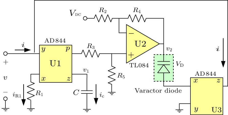
Fig. 1. The proposed MR emulator.
Download figure:
Standard imageThe variable capacitance of the varactor diode can be expressed as
where Cvd0 is the zero-bias diode capacitance, v denotes the reverse voltage, Vbi and γ are the built-in voltage and grading coefficient, respectively, and Cvd0, Vbi and γ are determined by the physical fabrication of the varactor diode. Note that expression (1) could induce high complexities into the calculation of the equivalent MR constitutive relation. Hence, in comprehensive consideration of the calculation simplicity and accuracy, Eq. (1) can be fitted by the quadratic polynomial function and written as

where a0, a1 and a2 are the fitting coefficients related to Cvd0, Vbi and γ.
As shown in Fig. 1, only three active devices including two CFOAs (U1 and U3) and one operational amplifier (U2) are required. U1 is used for structuring the integral circuit to obtain equivalent flux ϕ. U2 and the resistors R2, R3, R4, and R5 are together establishing the differential subtraction circuit to ensure that the varactor operates under a reverse bias voltage. According to the operation performance of CFOA U1, the current outflowing terminal z is equal to the current going through resistor R1. We have
Hence, the equivalent flux ϕ can be expressed as
Due to the function of the subtraction circuit, the output voltage of v2 can be expressed as
where
Since there is no current going into terminal y of U1, and the charge going into terminal z of U2 is equal to the charge inputting terminal x of U2, we have

Substituting Eq. (5) into Eq. (6), we can obtain

where
Hence, the MR memductance can be obtained by conducting a derivation operation on both sides of Eq. (7)
which reflects that the MR memductance can be timely varied by the equivalent flux ϕ. The value of ζ is equal to the initial memductance and can be adjusted by changing VDC.
The most attractive advantage of this newly proposed MR emulator is the requirement of fewer components. To comparatively display this advantage, the component numbers of the proposed and other reported MR emulators are listed in Table 1.
Table 1. Comparison of emulator component numbers.
| Objectives | Component numbers for MR emulation | ||||||||
|---|---|---|---|---|---|---|---|---|---|
| Ref. [7] | Ref. [8] | Ref. [9] | Ref. [10] | Ref. [11] | Ref. [12] | Ref. [13] | Proposed emulator | ||
| Op amps | 5 | 3 | 3 | 2 | 0 | 2 | 0 | 1 | |
| CFOAs | 0 | 0 | 0 | 0 | 4 | 2 | 2 | 2 | |
| Multipliers | 0 | 2 | 0 | 0 | 0 | 1 | 1 | 0 | |
| Capacitors | 1 | 1 | 1 | 1 | 4 | 1 | 3 | 1 | |
| Resistors | 14 | 6 | 9 | 3 | 4 | 5 | 4 | 5 | |
| Diodes | 0 | 0 | 1 | 4 | 2 | 0 | 0 | 1 | |
| Others | Active | 0 | 0 | 0 | 3 | 0 | 0 | 1 | 0 |
| Passive | 1 | 0 | 1 | 0 | 0 | 2 | 0 | 0 | |
| Total | 21 | 12 | 15 | 13 | 14 | 13 | 11 | 10 | |
It can be seen that, among the emulators listed in Table 1, the newly proposed emulator requires only ten components in total. The cells in the rows marked by Op amps, CFOAs, Multipliers and Active are filled by the number of active devices used for MR emulation. Evidently, only three active devices are required by the MR emulator shown in Fig. 1.
The varactor diode used for structuring the MR emulator is BB910 manufactured by Shenzhen SI Semiconductors Co., LTD. The black curve drawn in Fig. 2 is reconstructed based on the capacitance data provided by the Shenzhen SI Semiconductors Co., LTD. The red curve is fitted based on the measured data by using quadratic polynomial. The fitting coefficients can be calculated as a0 = 0.4666e−10, a1 = −0.1366e−10 and a2 = 0.0151e−10. Note that, higher fitting accuracy can be obtained by using higher order polynomial if necessary.

Fig. 2. The measured and fitted capacitance curve.
Download figure:
Standard imageThe MR emulator is firstly established by Multisim and the circuit parameters are configured as R1 = 150 Ω, R2 = R3 = R4 = R5 = 75 kΩ, C = 12 nF, and VDC = −2.5 V. A sinusoidal voltage of v = 0.3 sin(2πft) in units of V with frequency f = 4 kHz is employed to test the MR emulator. The simulation results displayed in Fig. 3 reveal that the current passes through the origin together with the excitation voltage, and the pinched hysteresis loop (PHL) of excitation voltage v and the input current i is behaving as an inclined 8. These observed behaviors are in good agreement with typical MR characteristics.
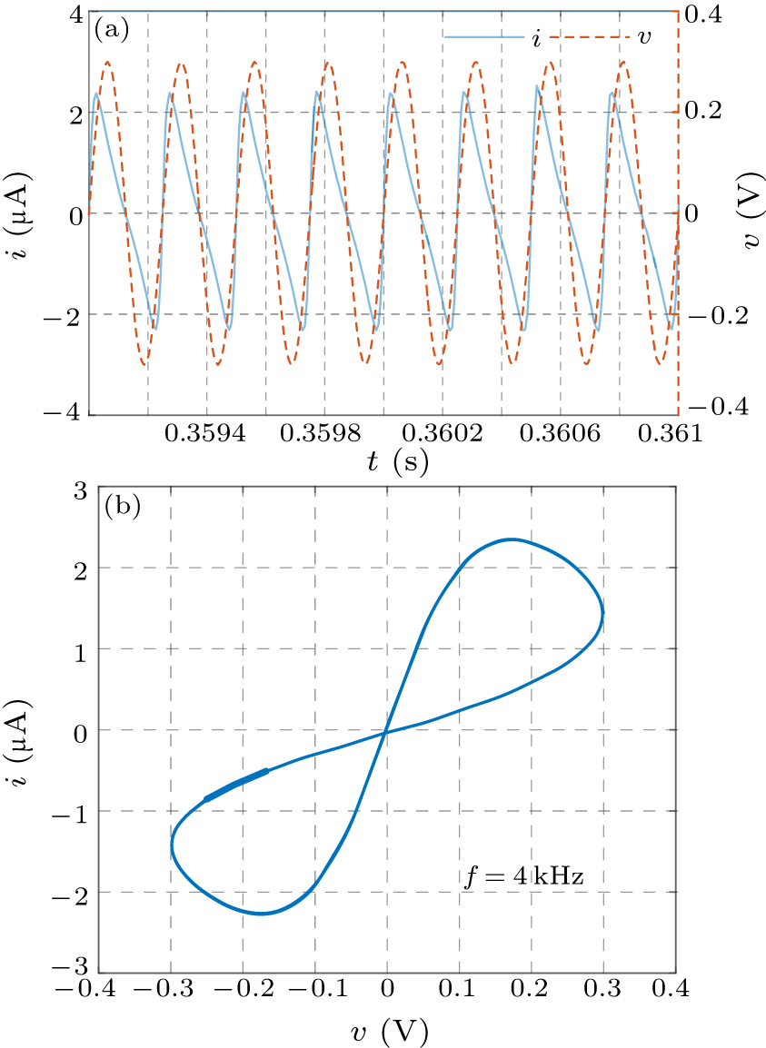
Fig. 3. Curves of the simulation results. (a) The simulation waveforms of v and i. (b) The simulation curves of the PHL.
Download figure:
Standard imageTo confirm the practical validation, the proposed emulator is built in hardware and then connected with a resistor of 10 kΩ in serial for testing, as shown in Fig. 4. Since the voltage vR across resistor R is in proportion to the current going through MR, vR is sampled for describing MR current i. By configuring the input voltage as vin = 0.3 sin(2πft) in units of V with f = 4 kHz, the sampled MR voltage v and equivalent current vR in time domain are shown in Fig. 5(a), which displays high similarity with Fig. 3(a). The PHLs structured by v and vR as frequency f equalling 4 kHz, 6 kHz and 9 kHz are presented in Figs. 5(b)–5(d), respectively. It can be seen that the PHLs are passing through the origin and evidently shrunk as the frequency f is increased, which is in good agreement with the typical feature of the MR called the frequency dependence of PHLs.

Fig. 4. The experimental test circuit.
Download figure:
Standard image
Fig. 5. The measured curves under sinusoidal excitation.
Download figure:
Standard imageFor the purpose of comprehensively testing, a triangle-shaped voltage with 0.3 V amplitude and 4 kHz frequency is then adopted for exciting the circuit shown in Fig. 4. The measured MR voltage v and current i (vR instead) in the time domain are presented in Fig. 6(a). Note that, although the measured current waveform shows an irregular shape, it is passing through the origin together with voltage v in stable periodicity. The Lissajous trajectory of v versus vR is sampled and redrawn in Fig. 6(b) with the blue colour. This PHL looks like two fan blades with sharp ends. These experimental results reflect that the proposed emulator could provide good performance under different excitation conditions.
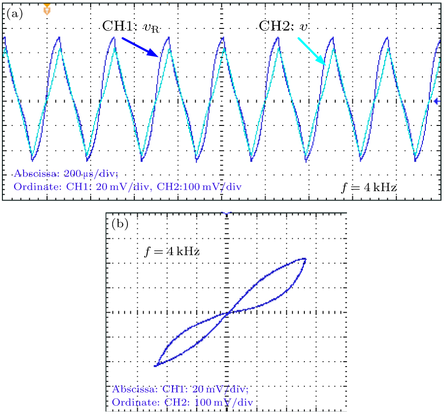
Fig. 6. The measured curves under triangular excitation.
Download figure:
Standard imageThe experimental results confirm that the proposed emulator with fewer components is capable of being practically applied, which is of great significance for designing or investigating emulator-based circuits, with the advantages of simple structure, small volume and low price.
In conclusion, making use of the controllable capacitance of the varactor diode, we propose a new MR emulator with fewer components, of which only three CFOAs, one capacitor and five resistors are required. The requirement of fewer components endows this MR emulator with the attractive advantages of smaller volume and lower price as compared with common emulators.