


Abstract
We demonstrate theoretically and experimentally an electromagnetic lensing concept using the magnetic vector potential—in a region free of classical electromagnetic fields—via the Aharonov–Bohm (AB) effect. This toroid-shaped lens with poloidal current flow allows for electromagnetic lensing which can be tuned to be convex or concave with a spherical aberration coefficient of opposite polarity to its focal length. This field-free lens combines the advantages of traditional electromagnetic and electrostatic field-based lenses and opens up additional possibilities for the optical design of charged-particle systems. More generally, these results demonstrate that the AB effect can shape charged particle wavefronts beyond simple step shifts if topologies beyond simple flux lines are considered and further supports the physical significance of the magnetic vector potential.
Export citation and abstract BibTeX RIS

Original content from this work may be used under the terms of the Creative Commons Attribution 4.0 license. Any further distribution of this work must maintain attribution to the author(s) and the title of the work, journal citation and DOI.
1. Introduction
The concept of an electromagnetic lens was first introduced in 1926 by Busch [1] and consists of a short solenoidal coil wrapping which produces a high magnetic field concentration in its central bore. Soon after this discovery, the first electron microscope was invented by Ruska [2] which opened up the ability to study a wide variety of structures, chemistry, and physics at length scales well beyond those of light microscopes. The lensing ability of these solenoidal electromagetic coils can be understood through the Lorentz force equation. The advantage of magnetic fields for lensing over electric fields is that the lensing forces are proportional to the electron energy as well as the field strength while electrostatic lensing is only proportional to the field strength. This allows a single electromagnetic lens to be used for a wide range of electron energies. A major limitation of round electromagnetic lenses for electrons was discovered early on by Scherzer [3] who proved that these lenses will always be convex (positive focal length) and always have positive spherical (Cs ) and chromatic (Cc ) aberration coefficients. The intrinsic aberrations of round electromagnetic lenses have long prevented direct electron imaging from reaching anywhere near wavelength-limited resolutions. Only in the last few decades has aberration correction with non-round multi-pole electromagnetic lens stacks become technologically possible [4–7] and pushed the resolution limits of transmission electron microscopes (TEMs) to sub-angstrom ranges.
Magnetic phenomena are usually explained in relation to the magnetic field. In the 1950 s, it was theorized by Aharonov and Bohm [8, 9] that electromagnetic potentials can cause physically observable phase shifts on charged particle waves in the absence of any electromagnetic fields. This was a non-intuitive result as the potentials are gauge fields and thus do not have a unique mathematical representation unlike electromagnetic fields. Due to this, the potentials in classical electrodynamics were widely considered to only be mathematical tools without direct physical relevance. The absolute phase shifts induced by the Aharonov–Bohm (AB) effect on a charged particle cannot be directly observed. However, the relative phase shifts between charged particles passing through different regions of the electromagnetic potentials are gauge invariant and can be measured through interference experiments (as proposed in Aharonov and Bohm's original paper). Although both electrical scalar potentials and magnetic vector potentials were considered by Aharonov and Bohm (the magnetic effect also described earlier by Ehrenberg and Siday [8]), the electrical version has not yet been satisfactorily verified experimentally [10]. In this work, we only consider the magnetic AB effect. For a magnetic vector potential to exist in the absence of a magnetic field, non-simply connected geometries (space with 'holes') are required.
Two of the main geometries that have been considered are that of an infinite-length solenoidal coil and a toroidal solenoid coil; both with steady-state currents flowing along their surface. The infinite-length solenoid is the geometry originally considered by Aharonov and Bohm and has been the focus of more studies than the toroidal geometry. Early experimental tests of the AB effect used the solenoidal geometry in the form of magnetic whiskers [11–13] or small solenoids [14] but faced issues with magnetic field leakage due to the impossibility of using infinite-length objects. The widely accepted experimental verification of the magnetic AB effect came from Tonomura's group in the 1980s [15, 16] in which they measured the shift in interference fringes from electrons passing through a shielded toroidal magnet by electron holography. From calculations on infinite-length solenoids, it has been shown that particles traveling on the same side of the solenoid would experience no relative phase shifts [17]. From this, a common assumption in the literature is that the AB phase shifts will only occur between particles whose paths enclose a non-zero magnetic field. We will demonstrate that this is not generally true and that relative phase shifts between trajectories enclosing no magnetic field can produce phase shift profiles with practical applications.
2. Results
2.1. Phase shift profiles from special coil geometries
We consider the cases of an infinite-length solenoidal coil and a toroidal solenoid coil with circular cross sections; both of which have analytic solutions for the vector potential in the Coulomb gauge [18]. Schematics of the coil geometries are shown in figures 1(a) and (b). We consider idealized versions of these coils such that steady-state currents flow with no helical pitch (i.e. purely in the azimuthal  direction for the infinite-length solenoid and in the poloidal
  direction for the toroidal solenoid). The relative phase shifts induced on electrons passing by each of these structures are calculated (details in supplementary materials sections 1.1 and 1.2). The shape of the integration loops used were chosen to approximate an electron plane-wave. Figure 1(c) shows a visual representation of the magnetic vector potential in the Coulomb gauge for the infinite-length solenoid. The relative phase shift profile for a plane-wave of electrons traveling in the positive
  direction in figure 1(c) is shown in figure 1(d). Here, it is apparent that there is a step-change in the relative phase from one side of the solenoid to the other (connected by a phase ramp for electrons passing through the region with magnetic field). If the current flow direction were flipped, the phase shifts would also be reversed. On the same side of the solenoid, there are no relative phase shifts as is generally expected for the AB effect. This lack of relative phase shift for particles passing on the same side of the infinite-length solenoid is a consequence of the vector field of the magnetic vector potential outside the solenoid being conservative and thus path independent. While this aspect of the AB effect is usually ascribed to Stokes' theorem, Stokes' theorem cannot actually be applied here due to the magnetic vector potential being non-continuously differentiable when the whole system is considered. However, as the infinite-length solenoid in 3D is homotopy equivalent to a circle (current loop) in 2D, it is actually Green's theorem being applied where the flux within the solenoid does not have to be considered (see supplementary materials section 1.1 for further details).

Figure 1. Calculations of the relative phase shift profiles from two coil geometries. (a) Schematic diagram of the infinite-length solenoidal coil with circular planar cross-section showing coordinate directions (Cartesian  and cylindrical
  ), shape parameter radius rs
, and current flow I in the azimuthal
), shape parameter radius rs
, and current flow I in the azimuthal  direction. (b) Schematic of the toroidal solenoid coil with circular planar and axial cross-sections showing coordinate directions (Cartesian
  , cylindrical
  , and simple toroidal
  ), shape parameters minor radius rs
and major radius rl
, and current flow in the poloidal
), shape parameters minor radius rs
and major radius rl
, and current flow in the poloidal  direction. (c) Vector plot of the magnetic vector potential (blue arrows) in the Coulomb gauge for a planar cross-section through an infinitely-long solenoidal coil. The red circle indicates the walls of the solenoid. The dashed rectangle represents an example integration loop. (d) Phase profile for an electron plane-wave that has traveled perpendicular to the solenoid in the positive
  direction. (e)) Vector plot of the magnetic vector potential in the Coulomb gauge (blue arrows) for an axial cross section of a toroidal solenoid coil. The color scale indicates the magnetic field strength (blue going into the page, red coming out of the page, lighter colors are weaker, white = zero). The red circles indicate the walls of the torus. (f) Phase profile for an electron plane-wave traveling in the positive
  direction that has passed through the toroidal solenoid coil. (g) The relative phase profile from (f) zoomed into the central hole of the toroidal coil.
Download figure:
Standard image High-resolution imageThe same calculations were repeated for the toroidal solenoid geometry as shown in figures 1(e)–(g). We note that a major difference between the toroidal solenoid in comparison to the straight solenoid is the presence of curvature which causes the current density on the inner and outer walls of the torus to be unequal. Figure 1(e) shows the analytic vector potential in the Coulomb gauge for the toroidal solenoid coil [18] which has a higher potential density in its central hole relative to outside. Figure 1(f) shows the calculated relative phase shift profile for an electron plane-wave traveling in the positive  direction. The phase shift profile of the torus exhibits a large step-shift in relative phase between regions outside the torus and inside the hole of the torus. This phase shift is what was observed in Tonomura's experiments. If the direction of the current through the torus is reversed, the phase shift profile is flipped. This is expected and was demonstrated in one of Tonomura's earlier experiments [19]. These features follow the traditional understanding of the AB effect. An unexpected feature observed here is that the relative phase profile is not completely flat in the regions outside the torus volume where the magnetic field is zero. There is a small phase curvature of much lower magnitude than the well-known phase step-shift. This demonstrates that the vector potential outside the toroidal solenoid is non-conservative. As a consequence, the phase accumulated by charged particles passing through the regions with zero magnetic fields are path-dependent. Thus, the degree to which the phase profile curves will depend on the size and shape of the integration curves used (which is not the case with the infinite-length solenoid).
The shape of the integration curves used for figures 1(e)–(g) were chosen to approximate an electron plane-wave. When we look more closely at the phase profile in the hole of the toroidal solenoid coil as shown in figure 1(g), the profile is close to parabolic which is a signature of lensing effects. An ideal lens phase profile can be fit very closely to the calculated relative phase profile in the torus. This suggests that the magnetic vector potential distribution inside the hole of a toroidal solenoid coil acts as a lens for charged particles. While this analysis precludes quantification of the lensing magnitude due to the path-dependent nature, some lensing properties that the toroidal solenoidal coil has can be identified.
2.2. An electromagnetic toroidal solenoid coil lens
By changing the current flow through the toroidal solenoid coil, the lensing strength can be varied; just as for traditional solenoidal electromagnetic coils. In traditional electromagnetic lenses, electrons follow a conical spiral path through the lens. By reversing the current flow direction, the handedness of the spiral reverses but not the focal length polarity. Therefore, these lenses can only be convex for negatively charged particles. With the toroidal solenoid coil, by reversing the current flow direction, the lensing direction of the coil can be flipped from convex to concave and vice-versa. Thus, the toroidal solenoid coil can act as a convergent or divergent lens for both positively and negatively charged particles (the focal length polarity will depend on the direction of current flow and the particle charge polarity). Additionally, no phase shifts are produced in the toroidal direction so no image rotation is produced as occurs with conventional electromagnetic lenses. In figure 1(g), we can see a reduced phase curvature at the edge of the toroidal solenoid coil lens relative to that of an ideal lens. This indicates that the toroidal solenoid coil has a Cs of opposite polarity to its focal length (e.g. when the coil is operated such that it has a positive focal length, it has a negative Cs ). This contrasts with a traditional electromagnetic lens which always has a positive non-zero Cs for electrons. The Cc of the toroidal solenoid coil will have the same polarity as the focal length due to the wavelength dependence of the beam deflection due to wavefront curvature.
That this toroidal solenoid coil lens has a spherical aberration coefficient of opposite polarity to its focal length is seemingly in contradiction with Scherzer's conditions [3, 20] for producing negative spherical aberration in electron lenses: 1. breaking rotational symmetry; 2. using time-varying fields; 3. using space-charges; and 4. producing a virtual image. The unstated assumption underlying these four conditions is that lensing takes place through electromagnetic fields. Scherzer's conditions thus do not apply to the present round, space-charge free, steady-state current lens as it is field-free. As the lens does not produce electromagnetic fields, it may be well suited for the imaging of magnetic samples. However, unlike the field-free objective lens recently developed by Shibata et al [21], a magnetic vector potential will still be present at the sample. The properties of this vector-potential-based lens are compared with existing lenses for charged particles in supplementary materials table SI.
2.3. Further physics of the AB effect
Due to the path-dependent nature of the vector potential field, the charged particles passing through it should follow paths determined by stationary action principles. Using the classical electron-optical refractive index parameterized by distance along the optical (z)-axis, the Euler–Lagrange equation can be solved numerically to calculate the trajectory of charged particles passing through a toridal solenoid coil (details given in supplementary materials section 1.4). Examples of calculated ray trajectories for parallel electrons entering a toroidal solenoid coil are shown in supplementary materials figure S2. These trajectories exhibit the same lensing behavior predicted by the phase-based analysis; namely that the focal length and spherical aberration coefficients have opposite signs and that their polarities can be reversed by switching the direction of current flow. That this effect can be calculated using classical Lagrangian methods challenges another previously held belief about the AB effect—that it is a purely quantum mechanical effect. With the infinite-length solenoid geometry, deflections can only be observed through double-slit type interference experiments centered about the solenoid. Such deflections have been described as being due to a 'quantum force' [22]. The present lensing deflections for the toroidal geometry appear even in the classical limit were the wave-nature of the particle is not considered. Thus, while this lensing effect cannot be explained by the Lorentz force, aspects of it can be explained classically—but only using the magnetic vector potential and not by the magnetic field. Therefore, the magnetic vector potential has physical significance not only in quantum mechanics but classically as well.
In early critiques of the AB effect, it was argued that fringing magnetic fields from any physically achievable finite-length solenoid could also cause the shifts in the interference patterns as predicted by Aharonov and Bohm. However, as argued by Berry [23, 24], as the solenoid approaches longer and longer lengths, the phase shift must approach a non-zero asymptotic limit even as the fringing fields approach zero. For the present case of the toroidal solenoid system, it could be argued that it is not physically possible to achieve a perfectly axially symmetric torus. Such an imperfect torus could have fringing magnetic fields as shown in supplementary materials figure S5 which would give rise to roughly radial deflections similar to those predicted in this paper. As with the straight solenoid system, the current work argues that in the limit of vanishing fields (by improving the axial symmetry in this case), a non-vanishing radial lensing effect is maintained within the central hole of the torus. As the axial symmetry of the system is increased, the stray fields will be more closely confined to the edges of the torus. Experimentally, these edge-confined fringing fields (e.x. in atomically round samples) will prevent the sharp cusp in phase at the edges of the sample from being observable. As long as the observed lensing effect is radially symmetric, the contribution of stray fields would be negligible.
It may be useful to note why previous quantum mechanical solutions to wave scattering from the toroidal magnetic field geometry [25, 26] have not predicted the present lensing effects. This is because none of these previous theoretical calculation on the toroidal geometry have used magnetic vector potentials calculated directly from the toroidal solenoidal coil current distribution. Instead, the vector potential distributions were calculated from magnetic flux loops via Stokes' theorem. In this work, we have shown that for geometries which deviate from the infinite-length solenoid coil, application of Stokes' theorem is not valid (details in supplementary materials section 1.3). Indeed, the infinite-length solenoid is a special case of the toroidal solenoid as the major radius rl becomes infinity. We also note that here, if we take the minor radius rs to zero as in the flux loop cases, while the lensing effect will decrease, it does not disappear. In fact, if all parameters but rs are maintained constant, the phase shifts in the hole of the torus normalized to the step-phase shift between the inner and outer walls of the torus remains constant as shown in supplemental materials figure S6. This demonstrates that despite the infinitesimal minor radius, the non-constant radial current density or magnetic field strength must be considered which is not for the flux-loop assumptions. For the phase step-shift behaviors that previous quantum mechanical models were interested in justifying, the error induced by the application of Stokes' theorem is negligible. However, it hides the phase curvature effects which can only be found using the magnetic circulation (supplementary materials equation (S29)) rather than the magnetic flux. We expect that if scattering models are developed using explicit representations of the magnetic vector potential, wavefront curvatures through the torus will be found. Such quantum mechanical scattering-based solutions would allow for proper quantitative calculations of the lensing effects.
The interpretation of the AB effect has been under debate for some time. In the original paper [9], two interpretaions were offered; that the effect could be ascribed to non-local interactions between the charged particles and the magnetic fields or to local interactions between the charged particles and the magnetic vector potential. Subsequently, several papers have argued for each interpretation [27, 28]. One of the main arguments for non-locality is that the AB effect only occurs when magnetic field lines (magnetic flux) is enclosed [29–31]. The current work demonstrates that phase shifts can occur between particles whose trajectories do not enclose any magnetic field. Thus, the current work further supports the physical significance of the magnetic vector potential. Any non-local interpretations will also need to account for the present phase curvature effect in non-straight solenoidal systems.
2.4. Experimental demonstration of the lensing effect
To test the lensing theory, we fabricated magnetic nickel nanorings on silicon nitride membranes (figures 2(a) and (c)). All experiments were performed in Lorentz-mode TEM where the objective lens is off to minimize the effects of the magnetic fields from the (conventional solenoidal electromagnetic) lenses on the samples. As a non-magnetic reference, gold nanorings of similar size and thickness (figure 2(e)) were also measured. Magnetic nanorings have several possible magnetization states. For the present experiment, we require toroidal magnetic fields within the ring material which is the flux closure magnetization state. Such rings were identified by electron holography (supplemental materials section 2.1). The phase resolution of the holography measurements is however not sufficient to measure the phase curvature.
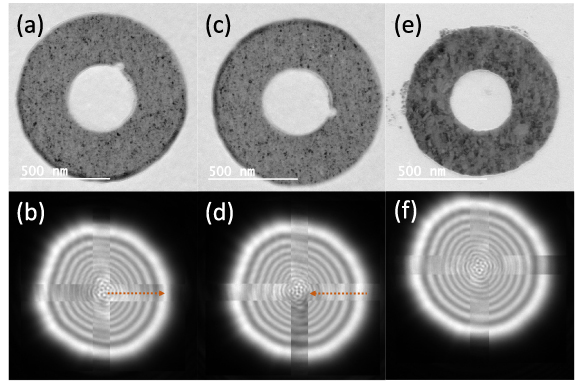
Figure 2. Experimental demonstration of the lensing phase profile inside a magnetic nanoring. (a), (c) and (e) Lorentz TEM images of nanoring structures. (b), (d) and (f) Convergent beam Fresnel electron diffraction patterns obtained with the beam inside the nanorings and in vacuum. The beam conditions were unchanged while the sample was moved for acquisitions in the nanorings and in vacuum. In these images, the Fresnel patterns from inside the nanorings and from vacuum are overlayed. The outer quadrants of the beam are the vacuum measurements while the inner cross is from inside the nanoring. (a) and (b) Nickel magnetic nanoring. (c) and (d) the same nanoring as in (a) and (b) but physically flipped to reverse the magnetization direction relative to the electron beam. (e) and (f) Gold non-magnetic nanoring. For the non-magnetic nanoring, there is no change in the Fresnel fringe pattern inside the nanoring and in vacuum. For the magnetic nanorings, the Fresnel pattern obtained inside the ring shifts relative to the vacuum pattern. The direction that the fringes shift reverse when the magnetic nanoring is flipped upside-down. The fringe shift directions are indicated with dotted arrows.
Download figure:
Standard image High-resolution imageTo measure the lensing effect from magnetic nickel nanorings with flux-closure vortex magnetization states, convergent nanobeams smaller than the central hole of the nanorings were formed. The probes were imaged in diffraction mode defocused away from the back focal plane such that Fresnel diffraction patterns were recorded as the electron beam passed through the ring. Reference diffraction patterns were obtained in vacuum without changing the beam parameters. In figure 2(b), the Fresnel fringes from a beam passing through the hole of a nickel nanoring are shifted slightly radially outwards relative to the reference beam through vacuum as would be expected for a beam being diverged (supplemental materials figure S4). The nanoring grid was then physically flipped to reverse the magnetization direction relative to the electron beam and Fresnel patterns collected from the same ring are shown in figure 2(d). Here, the Fresnel fringes are observed to shift slightly radially inwards as expected for convergent lensing. The non-magnetic gold nanoring control samples (figure 2(e)) showed no shift in the Fresnel fringe patterns between the inside of the nanorings and vacuum (figure 2(f)). The lensing polarities are consistent with what our theory (figures 1(f) and (g)) would predict based on the phase profiles measured by electron holography through the whole nanoring structures (supplemental materials figure S3).
The samples used were not magnetically shielded or electron opaque as in the experiments performed by Tonomura's group [15, 16]. This allowed for holography to be performed on the whole structure but means that some magnetic field may extend into the hole of the nanorings. While reversible concave–convex lensing is possible using time-dependant electromagnetic fields in intense laser pulses [32–34], as proved by Scherzer, there are no time-independent magnetic fields which can extend into free-space and produce radially symmetric convex and concave reversible phase profiles as observed in the present Fresnel diffraction experiments. If the currently observed fringe shifts were due to electrons passing through the volume of the nanorings (a magnetic field-based lensing effect [35–37]), the lensing effects would be in the opposite directions from those presently measured. Beam-induced charging effects of the support membrane also cannot explain the observed shifts in Fresnel fringes as the polarity of any induced charge would be the same whether the sample were flipped upside down or not and thus not reverse the fringe-shift direction. Thus the present Fresnel diffraction experiments provide experimental support for our theoretical conclusions.
To further establish the lensing effect, some other improvements in addition to shielded and flux confining nanorings can be considered. Even with magnetic shielding around the sample, there is a non-zero possibility for electrons passing through the hole of the nanoring to interfere with electrons passing outside the nanoring—leading to Shelenkov–Berry [38–40] type deflections. To eliminate such possibilities, a thick metallic sheet with a hole smaller than and concentric with the inner hole of the magnetic nanoring could be placed over the nanoring. This would prevent even the weak tails of a convergent electron probe from extending beyond the inner hole to truly verify that deflections can be caused without enclosing any magnetic flux. Additionally, if experiments could be performed using massive charged particles with negligible deBroglie wavelength, the 'classical' aspect of the lensing effect could also be verified.
As an additional test of the lensing effect due to the magnetic vector potential with the current sample, we also collected Fresnel diffraction patterns from convergent electron beams not centered in the nanorings (i.e. not along the optic axis). For axially symmetric lenses, radiation passing off the optic axis will gain a non-axially symmetric phase shift. A series of Fresnel diffraction patterns were obtained after a convergent electron probe was formed and the sample stage translated along one direction such that the electron probe was scanned through the center of a nanoring as shown in the top diagram of figure 3. As before, the microscope lens settings were not modified within each scan. Due to lack of precision in the stage shifts and drift, the exact position of the electron probe in the nanoring cannot be determined but the approximate positions are as depicted in the diagram. For the magnetic nanorings (the same ring as used in previous experiments), when the electron probe passes near the inner edge of the nanoring, a left-right asymmetry in the Fresnel fringe spacings is observed. As the probe is moved to the center of the nanoring, the asymmetry is no longer observed (the same conditions as in figure 2). As the probe continues to the other side of the nanoring, the asymmetry reappears but with the opposite orientation. For the electron probe passing through the non-magnetic gold nanoring, such asymmetry in the Fresnel fringes is not observed. Some image contrast in addition to the Fresnel fringes is observed in all cases due to irregularities in the support film (partially due to repeated exposures to the central region of the ring which could cause some charging effects). This contrast can be identified as it moves with the nanoring. When the magnetic nanoring is flipped upside-down, the way the left-right asymmetry in the fringe spacings appear reverses. For the right-side up case in figure 3, fringes toward the center of the nanoring are more closely spaced relative to the fringes closer to the edge of the nanoring. When the nanoring is upside-down, the fringes towards the center now have a wider spacing relative to the fringes toward the edge of the nanoring. These distortions to the fringes are again consistent with the results of the previous experiments and theory. We have thus experimentally demonstrated both on-axis and off-axis lensing effects of the magnetic vector potential from toroidal magnetic structures.

Figure 3. Fresnel diffraction patterns obtained at different radial positions through the center of nanorings (a magnetic nickel nanoring in the rightside-up and upside-down orientations and a non-magnetic gold nanoring). The top-center schematic represents the nanoring (blue ring) and the approximate positions (green dots) of the electron beam from which the corresponding diffraction patterns were obtained (columns under red arrows). The top-left diagram represents the shape of the phase profiles expected through the three rings shown (green concave = Ni rightside-up, yellow convex = Ni upside-down, purple flat = Au). The Fresnel fringes in the diffraction patterns obtained off-center through the magnetic nanoring exhibit left-right asymmetry. The off-center obtained Fresnel diffraction patterns through the non-magnetic nanorings do not exhibit left-right asymmetry.
Download figure:
Standard image High-resolution image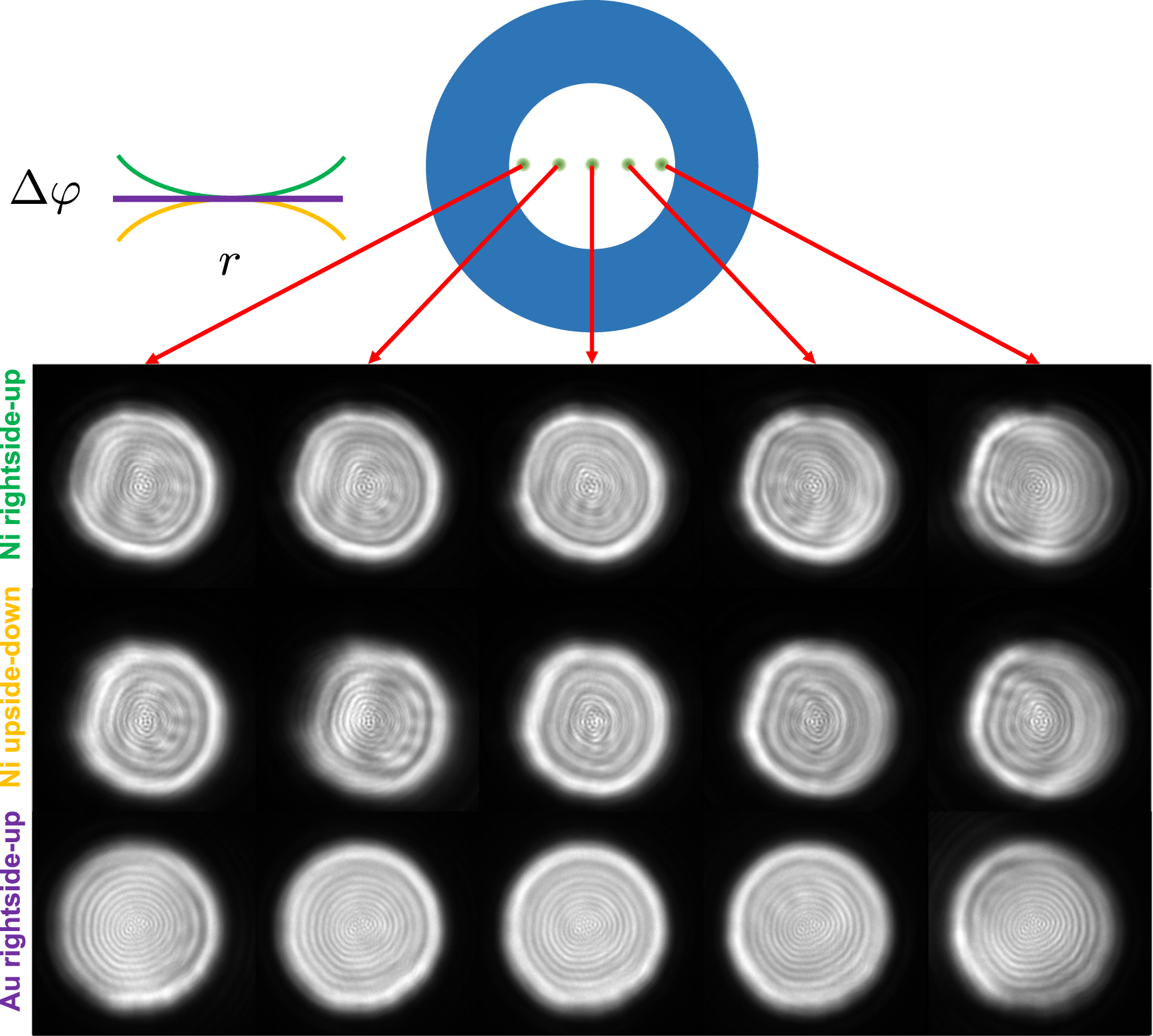
3. Conclusions
We have argued theoretically and demonstrated experimentally that the irrotational magnetic vector potential in the bore of a toroidal solenoid coil can act as an electromagnetic lens for charged particles through the AB effect. This electromagnetic lens is unique compared to existing round, time-independent, space-charge-free lenses as it can be made both divergent and convergent and has a negative spherical aberration coefficient while convergent. This vector-potential-based lensing concept has potential to be practically applied in charged particle optics systems such as electron microscopes. The aberration and reversable focal length properties in particular make it theoretically possible to design microscopes with near-zero spherical aberrations without the need for multi-pole aberration correctors. This lensing also for the first time demonstrates an AB effect where the measurable relative phase shift does not take place between particle trajectories enclosing a magnetic field. This supports the interpretation of a localized interaction between the charged particle and magnetic vector potential. Additional effects of the magnetic vector potential and perhaps other gauge fields may be found if higher order topological structures are investigated.
Acknowledgments
We would like to thank Dr Martin Linck (CEOS GmbH) for providing a protocol for the CETCOR image corrector to allow for larger fields of view in electron holography. We would like to thank Professor Takuya Mine (Kyoto Institute of Technology), Professor Dmitry Feichtner-Kozlov (University of Bremen, OIST) and Professor Rafael Ayala (University of Seville) for helpful discussions. The OIST Imaging section is acknowledged for use of the ETEM facility. The OIST Engineering section is acknowledged for use of the nanofabrication facilities.
Data availability statement
The raw experimental data and code that support the findings of this study are openly available at the following URL/DOI: 10.5281/zenodo.8253337 [41].
Funding
M T S was supported by JSPS fellowship (DC1) 201820215, JSPS Kakenhi Grant 18J20215 and Kakenhi Grant-in-aid for JSPS fellows 18J20132. C C was supported by JSPS Kakenhi Grant No. 18KO4247. M W was supported by the Platform Project for Supporting Drug Discovery and Life Science Research (BINDS) from AMED under Grant Number JP18am0101076. M T S, C C and M W are grateful for direct funding from OIST.
Author contributions
M T S conceived of the study and conducted the theoretical calculations. M S fabricated the nanoring samples. M T S and C C performed the electron microscopy experiments and data analysis. M T S wrote the manuscript. M W provided supervision.
Conflict of interests
A patent application on the toroidal solenoid electromagnetic coil lens has been filed by OIST with M T S, C C, and M W as inventors (PCT/IB2022/059206). All other authors declare they have no competing interests.
Appendix A: Vector potential phase shift profile calculations
Calculations were performed in MATLAB R2020b. Vector potentials fields in the Coulomb gauge were calculated based on analytical solutions for given geometrical and current parameters. The elliptic integrals were evaluated with the built-in function 'ellipke' with the default tolerance value with double floating point precision. Phase profiles were calculated by numerical integration of rectangular closed loops through the vector potential fields.
The geometric particle trajectories were calculated from using the NDSolve function in Mathematica 12.
Appendix B: Nanoring fabrication
Magnetic nickel nanorings of 60–70 nm thickness with a 5 nm titanium adhesion layer were grown on 8 nm thickness silicon nitride membranes (Electron Microscopy Sciences). Non-magnetic gold nanorings of 6070 nm thickness with a 5 nm titanium adhesion layer were grown on 50 nm thickness silicon nitride membranes (Norcada). Silicon nitride TEM window grids were cleaned for 5 min. with a soft oxygen plasma. 300 nm poly(methyl methacrylate) (PMMA) 950 K A4 was spin-coated onto the membranes and then soft baked for 3 min for solvent release. An ELS-7500EX electron-beam lithography system (Elionix, 50 kV acceleration, 100 pA current, 30 µm aperture) was used to write an array of nanoring designs with 200–600 nm inner diameters and 500–1000 nm outer diameters. The exposed layer of PMMA was then developed in MIBK:IPA solution at 1:3 ratio and consequently rinsed in isopropyl alcohol (IPA). A KE604TT1-TKF1 electron-beam evaporation system (Kawasaki Science) was used to deposit metals onto the exposed PMMA films. PMMA lift-off was achieved by soaking the grids for 1–2 h in acetone followed by a pipette flush with acetone and then in IPA.
The grids were subsequently coated with ∼10 nm amorphous carbon using a IB-29 510VET vacuum evaporator (JEOL) to reduce charging of the silicon nitride film during TEM observation.
Appendix C: Electron microscopy
A Titan G2 ETEM (Thermo Fisher Scientific) operated at 300 kV was used for holography and diffraction experiments on the nanorings. The microscope has a monochromator, Schottky XFEG electron source, S-TWIN objective lens, Lorentz lens, image Cs-corrector (CEOS GmbH), a single electrostatic biprism in the selected area plane, and a post-column Gatan Quantum 966 energy filter. UltrascanXP1000 (Gatan) cameras are located before and after the energy filter. Samples were loaded onto a model 2020 single-tilt tomography holder (Fischione). All experiments were performed in Lorentz mode such that the objective lens was off—minimizing the magnetic field at the sample plane.
Electron holography was performed on the nanoring samples to determine the magnetization states. As our single-biprism system has a limited field of view, a protocol from CEOS was used to manipulate the lenses in the image corrector to reduce the image magnification transferred to the selected area plane. Holograms were obtained from nanorings with the grid right-side up and upside-down to observe the reversal of the magnetization state with respect to the electron beam. The hologram reconstructions from the right-side up and upside-down nanorings were subtracted to isolate the magnetic contributions to the hologram. Reference holograms were obtained from substrate films areas far from the nanorings. A biprism bias of 100 V and camera exposure time of 2 s was used and a fringe contrast of  obtained on the substrate. The holograms were reconstructed using a custom script in MATLAB with a 50 pixel radius hard virtual aperture. A Magnitude-Sorted List, Multi-Clustering Phase Unwrapping Algorithm [42] was utilized to unwrap the phase maps. The phase maps were smoothed with a 16 pixel Gaussian blur filter to reduce the influence of a few regions which could not be properly phase unwrapped.
For the Fresnel diffraction patterns measurements, the electron beam was converged to a size smaller than the inner radius of the nanorings ( 100 nm). The electron beam was centered in the nanoring and Fresnel diffraction patterns recorded. After recording the Fresnel pattern from the beam in the hole of the nanoring, a reference pattern was recorded in vacuum by moving the sample so that the beam conditions were unchanged. Diffraction pattern pairs were obtained for nanorings both in the right-side up and upside-down orientations.
Supplementary data (8.7 MB PDF) Theory and experimental details