Introduction
Published December 2021
•
Copyright © IOP Publishing Ltd 2021
Pages 1-1 to 1-23
You need an eReader or compatible software to experience the benefits of the ePub3 file format.
Download complete PDF book, the ePub book or the Kindle book

Permissions
Abstract
Classification of materials based on symmetry operations. Fundamentals of ferroelectricity and related phenomenon, classification of ferroelectrics based on structure and properties are presented in this chapter. The structure and properties of Aurivillius phase oxides are also discussed in detail.
1.1. General introduction
Materials scientists have long been interested in materials engineering, i.e. modifying existing materials and the synthesis of new materials to arrive at desired properties which can be tuned to a specific activity. Currently, materials for different applications are available in different forms such as single crystals, polycrystallines, and thin or thick films. Of these materials, ceramics are of current interest since they can be used as electrical conductors (e.g. for humidity sensors or fuel cells), semiconductors for energy conversion, and insulators for dielectric, ferroelectric, pyroelectric, or piezoelectric applications [1, 2]. The materials that have been specially designed for specific electrical, magnetic, and optical applications are now classified under electroceramics as distinct from other types such as advanced structural ceramics.
The sub-classes of electroceramics have grown in a parallel manner, for example, ferroelectrics for high dielectric capacitors and non-volatile memories, ferrites for data and information storage, solid electrolytes for energy storage and conversion, piezoelectrics for sonar, semiconducting oxides for environmental monitoring, and a host of others. Micro-sensors and micro-actuators based on electroceramics are being fabricated in which ceramic materials and micro-technology are combined to form efficient micro-devices for production control, environment monitoring, and biomedical applications.
The history of ferroelectricity began about 80 years ago, with the discovery of Rochelle salt (sodium potassium tartarate tetrahydrate (NaKC4H406.4H20)), which shows the peculiar phenomenon of 'ferroelectricity'. Valesek [3] observed this phenomenon in Rochelle salt for the first time from the measurement of its dielectric properties. Initially it was thought that this peculiar phenomenon in Rochelle salt is due to its complicated structure, but this impression vanished gradually with the discovery of similar phenomenon in a series of other compounds. The first systematic attempt to compile a list of ferroelectrics was carried out by Jona and Shirane [4].
The name 'ferroelectricity' is a consequence of the phenomenological similarity with ferromagnetism. There is no relation between ferromagnetism and ferroelectricity. The development of ferroelectric materials in order to improve the ferroelectric properties led to widespread industrial and commercial applications. In the race of device miniaturization, smart ceramic materials are technologically significant, particularly in sensors, actuators, transducers, memory devices, and capacitors.
In the early 1950s, most of the applications in the field of capacitors and piezoelectric sensors used only BaTiO3 (BT) based ceramics. Thereafter, various other ferroelectric ceramics including lead titanate (PbTiO3), lead zirconate titanate (PZT), lead lanthanum zirconate titanate (PLZT), and relaxor ferroelectrics such as lead magnesium niobate (PMN) were developed and utilized in various device applications that can be credited directly to this most unusual phenomenon [5]. Due to the excellent piezoelectric properties of lead-based ceramics, they are the most commonly used piezoelectrics and are used widely in ferroelectric random access memory (FRAM), actuators, and sensors.
However, as lead-based ceramics contain lead—a highly toxic substance—as a part of their chemical composition, it leads to environmental hazards. Thus, there is a requirement for lead-free ferroelectric materials with high performance that can substitute lead-based ferroelectric ceramics.
Therefore, alternative lead-free materials, namely bismuth layer structured ferroelectrics (BLSF) belonging to the Aurivillius family, are being prepared for advanced memory applications. Moreover, these materials are compatible with CMOS technology [6]. BLSF materials are also referred to as future promising smart memory materials. These bismuth based ferroelectric materials present the following important properties:
- (i)High Curie temperature (300 °C–900 °C).
- (ii)High anisotropy.
- (iii)Fatigue free nature.
- (iv)Lower crystallization temperature.
- (v)Lead-free nature.
- (vi)Good piezoelectric and pyroelectric response.
The properties of ferroelectrics depend largely on the domain structure, the nature of interaction between the domain boundaries, and various sorts of defects. Detailed impedance and conductivity analysis is very sensitive to the motion of defects and domain walls and is useful in understanding the effect of oxygen vacancies and the pinning of domain walls. Therefore, these investigations are very important in improving the ferroelectric properties of materials.
1.2. Materials classification on the basis of symmetry
The symmetry of different materials, such as single crystals, thin films, and polycrystalline or amorphous materials, influences their physical properties. According to Neumann's principle, the external properties of a material are dependent on the internal crystal structure symmetry [7]. Four symmetry operations are employed to understand the symmetry about a point in space. They are: (i) the centre of symmetry, (ii) the axes of symmetry, (iii) the plane of symmetry, and (iv) a combination of the above [8]. Based on these symmetry operations solids are divided into a total of 32 crystal classes (point groups).
Dielectric materials belong to any one of the 32 crystal classes (point groups). Of these, 11 are centrosymmetric, i.e. they possess a centre of symmetry, and 21 are non-centrosymmetric. Among the non-centrosymmetric point groups, twenty groups are piezoelectric, in which the polarization can be induced with the application of mechanical stress. Out of these 20 piezoelectric point groups, ten point groups belong to the category of polar materials, which possess spontaneous polarization even in the absence of any applied electric field or stress. They are called pyroelectrics, as the spontaneous polarization in these materials is detected by heating these samples. The asymmetry inside the elementary crystal unit cell is the key reason for spontaneous polarization in the case of polar materials. Those polar materials whose direction of spontaneous polarization can be altered by the application of an external electric field are known as ferroelectrics. The classification of materials based on symmetry operations is shown in figure 1.1 and the flow chart for the same is shown in figure 1.2.
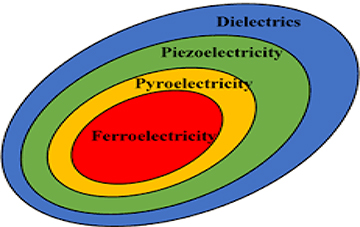
Figure 1.1. Classification of dielectric materials.
Download figure:
Standard image High-resolution image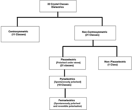
Figure 1.2. Materials classification on the basis of symmetry.
Download figure:
Standard image High-resolution image1.3. The basics of ferroelectricity and related phenomenon
1.3.1. Dielectric materials
Dielectrics are a special kind of insulating materials. As they are insulators, they possess virtually no free charge carriers. When dielectric materials are placed in an external electric field they undergo polarization. Polarization is the process of displacement of oppositely charged particles in opposite directions due to an externally applied field, which results in the formation of a permanent dipole moment. The strength of the dielectric properties of materials is measured in terms of the dielectric constant (ε) or relative permittivity (εr ). The dielectric constant (ε) or relative permittivity (εr ) is the measure of the ability of the material to be polarized in response to an applied electric field. Hence the greater the dielectric constant of a material, the greater is the polarization developed in a material for a particular applied field strength.
The energy stored in a capacitor is

The total capacitance (C) of a capacitor is given by


where, ε0 is the permittivity of the free space, ε is the permittivity or dielectric constant of the material which is equal to εo *εr , d is the distance between the parallel plates, and A is the area of the plates:

εr * represents the complex permittivity, the real part of permittivity (εr ') is a measure of the energy stored in a material. The imaginary part of the permittivity (εr '') is a measure of the energy lost in the material when an external electric field is applied. It is always greater than zero and is usually much smaller than the real part of permittivity (εr '). When the complex permittivity is plotted as a simple vector diagram (figure 1.3), the real and imaginary components are 90° out-of-phase. The vector sum forms an angle δ with the real axis (εr '). The relative 'lossiness' of a material is the ratio of the energy lost to the energy stored. The loss tangent or tanδ is defined as the ratio of the imaginary part of the dielectric constant to its real part. D denotes the dissipation factor and Q is the quality factor. The loss tangent tanδ is called the tangent loss or dissipation factor. Sometimes the term 'quality factor or Q-factor' is used with respect to an electronic microwave material, which is the reciprocal of the loss tangent. For very low-loss materials, since tanδ ≈ δ, the loss tangent can be expressed in angle units, milliradians or microradians:


The dielectric susceptibility χ of the material is the parameter that relates the applied external electric field (E) and electrical polarization (P) by the relation


Figure 1.3. Loss tangent vector diagram.
Download figure:
Standard image High-resolution imageAlso, εr of an isotropic medium is defined by the relation

where ε0 E + P = D is the electric displacement field.
Therefore, the energy stored in a dielectric material is directly proportional to the dielectric constant of the material. The total polarization in a dielectric material is a combinational contribution of four different polarization mechanisms which depend on the frequency of the externally applied electric field.
The four mechanisms of polarization are the following.
When an atom is placed in an external electric field, the centre of mass of a spherical electron cloud of uniform density is displaced slightly with respect to the centre of mass of the nucleus with the charge +Ze due to the electrostatic force. This causes an induced dipole moment which results in electronic polarization (Pe ).
When the sharing of electrons among the atoms of a molecule is not symmetrical then in such cases ions acquire partial opposite charge. When such a molecule is placed in an external electric field, the net charge tends to change the equilibrium position of the ions themselves. Thus when an external electric field is applied, the positive and negative sub-lattices are displaced in opposite directions. This gives rise to an induced dipole moment resulting in ionic polarization (Pi ).
In some molecules, there is a permanent dipole moment even in the absence of an external electric field. This permanent dipole moment experiences a torque in the presence of an external applied electric field. This mechanism gives rise to orientational polarization (Po ). For orientational polarization the molecule must possess a permanent dipole moment.
In addition to these three polarization mechanisms, one more polarization mechanism, known as the space charge polarization mechanism, also exists. The polarization which occurs due to the accumulation of charges at the electrodes or at the interfaces is known as space charge polarization (Ps ) or interfacial polarization. The main cause of space charge polarization is diffusion, in which the charges migrate over a limited distance under the influence of an applied field and forms positive and negative space charges at the grain boundaries or at the electrode–material interface. Except for Po , all other kinds of polarization, that is Pe , Pi , and Ps , are independent of temperature. The total polarization (PT ) of a material is given by the contribution due to all types of polarizations:

In the lower frequency region all types of polarizations (electronic, ionic, orientational, and interfacial) contribute to total polarization which gives rise to a high value of the dielectric constant. However, as the frequency increases, it becomes difficult for the dipoles to orient themselves in the direction of the applied electric field during each alternation of the electric field. Hence, a low value of dielectric constant at high frequency is obtained. The dependence of the polarization on frequency also indicates the time for which a particular mechanics of polarization remains. Electronic polarization (Pe ) is the fastest and occurs completely at the instant the voltage is applied. It persists around 1013–1015 Hz and occurs during every cycle of applied voltage. Ionic polarization (Pi ) is slower compared to Pe as ions are heavier than atoms, so the time taken for displacement is greater and it occurs at frequencies between 109–1013 Hz. Orientational polarization occurs around 109 Hz and is slower than Pi . The slowest is the space charge polarization occurring between 50–60 Hz since it involves the diffusion of ions over several interatomic distances. Figure 1.4 represents the dependence of each polarization mechanism as a function of frequency.
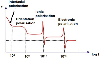
Figure 1.4. Variation of polarization with frequency.
Download figure:
Standard image High-resolution image1.3.2. Impedance spectroscopy
Complex impedance spectroscopy is a powerful tool used for studying the electrical properties of polycrystalline materials. Most of the electrical properties are affected strongly by the microstructure, and impedance spectra usually contain features that are related directly to the microstructure (the grain and grain boundaries of differing phase compositions, the suspension of one phase within another, the porosity, electrode interface effects, etc). It also enables us to evaluate the relaxation frequency ωmax of the material. The relaxation frequency of the material at a given temperature is an intrinsic property of the material independent of the geometrical factors of the sample. The contribution of various processes such as grain, grain boundary, and electrode–sample interface effects, etc, can be resolved in the frequency domain. Impedance is the sum of resistance and reactance in which the latter is a function of frequency. Any material can be considered as a combination of resistance and reactance either in series or in a parallel combination of both. In the parallel mode admittance (Y) is dominant and in the series mode impedance (Z) plays a vital role. The parallel mode is more appropriate for inductive samples and the series mode for capacitive samples. Electrical insulators can be characterized using ac impedance data. There are various formalisms by which one can exploit the wealth of data. The effects which do not show up in one of the formalisms show up in another. All the four formalisms are interrelated. The different formalisms are electric modulus (M), admittance (Y), permittivity (ε), and impedance (Z), after Sinclair et al [10]. They are


Different graphical analyses can be performed using these three equations. The general forms of data presentation are complex impedance plots (Z'' versus Z'), loss spectra (ε'' or M'' versus frequency), and the plots of ε', σ', or σ'' versus frequency. Usually, a peak is observed when a graph with these dielectric parameters is plotted with frequency. These peaks within a particular frequency range depend on the strength of relaxation. The data over a wide range of frequencies give additional information compared to fixed frequency dielectric data. Particularly, polycrystalline materials exhibit a wide variety of properties depending on the frequency. Such studies would help in understanding the dielectric nature, conduction processes, and possible relaxation phenomena. Any intrinsic property that influences the conductivity of an electrode–material system or an external stimulus can be studied by impedance measurement. The parameters derived from such a study fall into two categories (i) those relevant only to the material itself, such as conductivity, dielectric constant, etc, and (ii) those pertinent to an electrode–material interface such as the adsorption–reaction rate, capacitance of interface regions, diffusion coefficients, etc [9]. All ferroelectric materials have coupled electrical and mechanical properties. The impedance data, generally compared to an equivalent circuit, are obtained, which represent physical processes taking place in the system under investigation. An equivalent circuit is made up of ideal resistors, capacitors, inductance, and possibly various distributed circuit elements. In such a circuit, the resistance represents a conductive path and a given resistor in the circuit might account for the bulk conductivity of the material. Similarly, capacitances and inductances will be generally associated with various polarization processes. The total impedance of a polycrystalline material is the sum of the grain, grain boundary, and electrode effects [10]. By analysing the results on impedance data in more than one of the formalisms, it may be possible to separate these effects effectively.
1.3.3. Piezoelectricity
Piezoelectricity was first discovered by Jacques and Pierre Curie [11]. Piezoelectricity is defined as 'electrical polarization produced by applying mechanical strain to a crystal'. The polarization produced is directly proportional to the mechanical strain applied to the crystal. A basic requirement for a material to show piezoelectricity is that it must lack a centre of symmetry of the unit cell. This non-centrosymmetry of the unit cell creates an asymmetric charge distribution, which results in the formation of an electric dipole in the crystal as a whole. The converse is also true, i.e. when voltage is applied across the surface of the crystal the strain is produced across the surface. This strain produced in a crystal is directly proportional to the applied electric field.
The direct and converse piezoelectric effects are shown in figure 1.5 and can be expressed in tensor notation as


where Di is the polarization generated along the k-axis in response to the applied stress σjk . For the converse effect Sij is the strain generated in a particular orientation of the crystal by the application of the electric field Ek along the k-axis [7, 12] and dijk and dkij are the piezoelectric coefficients for the direct and converse effects, respectively.

Figure 1.5. Schematic diagram of the direct and converse piezoelectric effects.
Download figure:
Standard image High-resolution image1.3.4. Pyroelectricity
Pyroelectric materials belong to a category of non-centrosymmetric polar crystals that possess coupling between the electrical polarization P and temperature T, such that a change in temperature results in a change in the electric dipole moment. In pyroelectric materials, the spontaneous polarization is not necessarily switchable using an applied electric field. These materials can be used for converting thermal energy to electric energy. Pyroelectricity is the ability of the materials to generate a temporary voltage when they are heated or cooled. As a result of the temperature difference generated across the crystal, positive and negative charge displacement takes place. Due to this relative displacement of charges, the material becomes polarized (as a molecule possesses a permanent dipole moment) and hence a potential difference is generated.
The pyroelectric coefficient (pi ) is described as the change in the spontaneous polarization with temperature [13] as

where (Cm−2 K−1) is the unit of the pyroelectric coefficient.
Alternatively, pi is calculated using the relation

where I is the pyroelectric current measured during the heating cycle, A is the area of the electrode, and  is the rate of heating. The spontaneous polarization disappears above the Curie temperature (Tc
), the temperature above which a pyroelectric unit cell transforms into the centrosymmetric paraelectric phase. In the centrosymmetric paraelectric phase no dipole moment exists within the unit cell and thus it exhibits a reduced piezoelectric effect [5].
is the rate of heating. The spontaneous polarization disappears above the Curie temperature (Tc
), the temperature above which a pyroelectric unit cell transforms into the centrosymmetric paraelectric phase. In the centrosymmetric paraelectric phase no dipole moment exists within the unit cell and thus it exhibits a reduced piezoelectric effect [5].
1.3.5. Ferroelectricity
The subclass of dielectric materials in which spontaneous polarization exists even in the absence of an electric field and the polarization can be reversed with the direction of the applied external field are called ferroelectric materials. Ferroelectrics are polar dielectric materials that possess at least two equilibrium orientations of the spontaneous polarization vector in the absence of an external electric field, and in which the polarization may be switched between those orientations by means of an electric field. The magnitude of the external electric field applied should be less than the dielectric breakdown of the material itself. Therefore, for the material to show ferroelectricity it must possess the following properties:
- 1.Spontaneous polarization.
- 2.The direction of polarization can be reversed by an externally applied electric field.
- 3.A ferroelectric hysteresis loop.
- 4.A ferroelectric transition temperature.
Ferroelectric materials must possess non-centrosymmetric structure. As the material is non-centrosymmetric, ferroelectricity arises due to the change in the positions of the cations and anions within the unit cell, resulting in reversible spontaneous dipole moments. This gives rise to a dipole moment equal to qd/V, where q is the electric charge on a displaced ion, d is the relative displacement, and v is the volume of the unit cell.
The dipole moment is related to the electric displacement as

where χ0 and χ are the free space and relative susceptibilities, respectively.
Ferroelectric materials show the phase transition phenomenon. These materials undergo phase transition from ferroelectric to paraelectric above a certain temperature. During this phase transition they undergo a change in symmetry. The temperature at which the phase transition occurs is called the Curie temperature (Tc ). At this temperature the symmetry of the material changes from the non-centrosymmetric to symmetric phase. Due to a change in the symmetry above the Curie temperature, spontaneous polarization will be lost and the ferroelectric material becomes paraelectric. Hence, at the Curie temperature the hysteresis curve becomes linear. In addition to the change in spontaneous polarization, temperature affects the dielectric constant of the materials.
The spontaneous polarization (Ps ) decreases with an increase in temperature and vanishes at a transition temperature (Tc ), while the temperature dependence of the dielectric constant (ε) shows a sharp peak at Tc as shown in figure 1.6. The Curie–Weiss temperature (To ) coincides with the true transition temperature Tc for a ferroelectric material, which undergoes a second-order phase transition. However, in the case of a first order phase transition, the Curie–Weiss temperature To is several degrees lower than the transition temperature (Tc ).
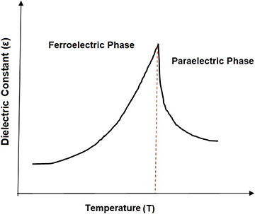
Figure 1.6. Variation of the dielectric constant with temperature.
Download figure:
Standard image High-resolution imageSome ferroelectric materials do not show a sharp peak in the temperature dependence of the dielectric constant at the transition temperature. Such materials show a broad peak at the transition temperature instead of a sharp peak. This type of dielectric behaviour is called a diffuse phase transition (DPT). It is well known that the dielectric constant/permittivity of a classical ferroelectric material above the transition temperature follows the Curie–Weiss law. However, the dependence of the dielectric permittivity of DPT ferroelectrics on a temperature above the transition temperature differs from the Curie–Weiss law over a wide temperature range. Smolenskii et al [14] predicted the following quadratic dependence of the dielectric permittivity on temperature:

where εm is the dielectric permittivity maximum, Tm is the temperature at which εm occurs (transition temperature), and d is the deviation factor that describes the degree of the DPT. However, Uchino et al [15] found that for many relaxor ferroelectric materials, the diffuseness does not exactly obey Smoleskii's [16] quadratic law and they then proposed an empirical expression to describe the diffuseness of the phase transition:

In this expression γ is the degree of diffuseness and ranges from 1 to 2 for normal to relaxor ferroelectrics. The relaxor behaviour in the sample is observed due to polar domain fluctuations in the neighbourhood of the maximum permittivity and is reflected in the values of γ [17].
1.3.5.1. Hysteresis loop
The ferroelectric properties of a material are studied using a hysteresis P–E loop, as the ferroelectric materials exhibit hysteresis analogous to ferromagnetic materials. For these materials polarization is not a unique function of applied electric field strength. However, in dielectric materials, in general, polarization is a linear function of applied field strength, whereas it not a linear function in ferroelectric materials.
The ferroelectric specimen that is not previously subjected to an applied external electric field is said to be a virgin ferroelectric specimen. If this virgin specimen of ferroelectric material is subjected to an applied external electric field and this field is gradually increased, the polarization P increases along the curve 'ABCD' as shown in the figure 1.7. When the field gradually decreases, it is found that even when the applied electric field becomes zero (E = 0) there is polarization still left in the specimen. This polarization is called remanent polarization (Pr ). In other words, the material is said to be 'spontaneously polarized'. The electric field is to be applied in the opposite direction in order to bring the polarization to zero. The required electric field to reduce the polarization to zero is called the coercive field (Ec ).
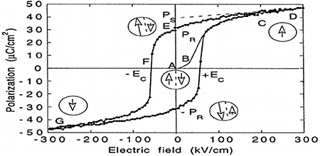
Figure 1.7. The hysteresis loop of ferroelectric materials. Reproduced with permission from [17]. Copyright 1998 IOPscience.
Download figure:
Standard image High-resolution imageThe existence of a hysteresis loop in a material implies that the substance possesses spontaneous polarization, i.e. polarization when the applied field is zero. Extrapolation of the linear segment Ps which intersects on the P-axis at a value Ps is the maximum value of polarization attained by the specimen and is called the saturation polarization (Ps ) and specimen is said to be saturated. Spontaneous polarization of a specimen depends on:
- 1.The dimensions of a specimen.
- 2.Temperature.
- 3.Humidity.
- 4.The texture of the crystal.
- 5.The previous history of the specimen.
1.3.5.2. Ferroelectric domain theory and domain walls
A quantitative explanation of hysteresis in ferroelectric materials is given by the domain theory of ferroelectrics. According to the domain theory, ferroelectric materials possess regions with uniform polarization called ferroelectric domains, i.e. within a domain all electric dipoles are aligned in the same direction (shown in figure 1.8).

Figure 1.8. Ferroelectric domains and domain walls. Reproduced with permission from [17]. Copyright 1998 IOPscience.
Download figure:
Standard image High-resolution imageThe direction of polarization is not the same throughout the specimen. In fact, the specimen may be considered to consist of a number of domains. These domains themselves become spontaneously polarized but the direction of polarization varies from one domain to another domain. Thus, the virgin specimen may have zero polarization as a whole, i.e. the resultant polarization vector of the domains may vanish.
When an external electric field is applied, the domains in which the polarization points along the direction of the applied electric field grow at the expense of other domains in which the polarization points in the other direction. This process corresponds to the curve 'ABC' in figure 1.7.
The domains in the specimen are separated by interfaces called domain wall. The walls between domains with opposite orientation and mutually perpendicular polarizations are called the 180° and 90° walls, respectively [18]. A single domain can be obtained by domain wall motion made possible by the application of an appropriate externally applied electric field. The specific mechanism of domain wall motion is simply the small shift of the ions' positions within the unit cell resulting in the net change of orientation of the tetragonal C-axis. Such domain wall motion results in spontaneous polarization (shown in figure 1.8).
1.4. Classification of ferroelectrics
Ferroelectric materials can be classified on the basis of their structure and properties.
1.4.1. Classification of ferroelectrics based on crystal structure
Depending on the structure, the ferroelectric materials are classified into four major categories.
1.4.1.1. Perovskites
Perovskite is the family name of a group of materials with an archetypal ABO3 type structure. Here the A-site is occupied by divalent cations such as Ba2+, Sr2+, Ca2+, and Pb2+, which are usually larger than the B-site cations that are tetravalent, such as Ti4+, Zr4+, and Sn4+, and O represents the oxygen atoms. The A-site cations are surrounded by twelve anions in a cube-octahedral coordination and the B-site cations are surrounded by six anions in an octahedral coordination. Many piezoelectric (including ferroelectric) ceramics such as barium titanate (BaTiO3), lead titanate (PbTiO3), lead zirconate titanate (PZT), lead lanthanum zirconate titanate (PLZT), lead magnesium niobate (PMN), and potassium niobate (KNbO3) have a perovskite type structure [19].
A typical ABO3 unit cell structure of BaTiO3 is illustrated in figure 1.9 and can be viewed as a closely packed cubic cell with large cations (A) at the cube corners, small highly charged cations at the body centre, and oxygen ions at the face centres. The structure is a network of corner-linked (BO6) octahedral holes and the large cations filling the dodecahedral holes [20]. The A-site cations are in 12-fold coordination with oxygen ions and the B-site cations are in six-fold coordination. The terms A- and B-sites are used frequently in describing perovskites and perovskite-like structures. Goldschmidt [21] determined the size of the cations that can be accommodated by the perovskite structure. The A-site can contain ions with ionic radii [22] between 1.34 Å (Ca2+) and 1.61 Å (Ba2+) while the B-site can accommodate ions from 0.535 Å (Al3+) to 0.87 Å (Ce4+). Figure 1.9 shows the cubic and tetragonal perovskite structures with dipole moments. Generally, perovskite structure materials are ionic in nature.
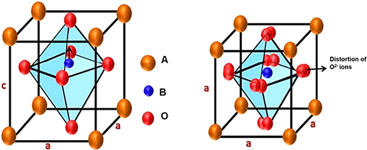
Figure 1.9. Cubic and tetragonal perovskite structures. Reproduced from [23] with permission of The Royal Society of Chemistry.
Download figure:
Standard image High-resolution image1.4.1.2. Tungsten bronze
Tungsten bronze structure can be represented by nonstoichiometric compounds with the general formula Mx WO3 (0 < x < 1) where M is an alkali metal. It is a highly coloured lustrous crystalline compound. The 'tetragonal tungsten bronze' (TTB) structure consists of interconnected corner-sharing oxygen octahedrals with three types of pseudo-symmetric open channels (three-, four-, and five-fold), which is a typical characteristic of the TTB crystal structure. It is related to the potassium tungstate (K0.475WO3)-like structure. The general formula for the TTB ferroelectric crystal structure is given by (A1)2(A2)4(C)4(B1)2(B2)8O30 [24]. The TTB structure is shown in figure 1.10.
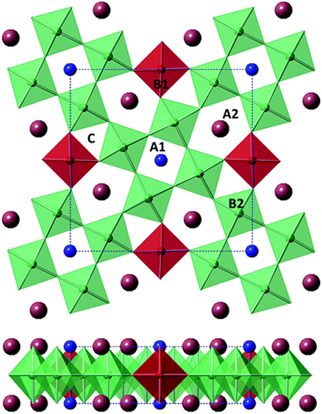
Figure 1.10. The TTB structure. Reproduced from [24] with permission of The Royal Society of Chemistry.
Download figure:
Standard image High-resolution imageIn TTB there are three open channels (the A1-, A2-, and C-sites) and the space occupied by the oxygen octahedron (B1 and B2) can accommodate a broad range of cations and anions. Hence, different properties can be tailored in TTB.
The first crystal of the tungsten bronze type structure to show useful ferroelectric properties was lead niobate (PbNb2O6) [3]. Various dopings in the TTB structure have led to the discovery of many new normal and relaxor-type ferroelectrics [25].
1.4.1.3. Pyrochlore
The general stoichiometric formula of pyrochlore structure ferroelectric material is A2B2O7 [26], where A represents a trivalent or divalent cation and B represents a tetra- or pentavalent cation. Figure 1.11 shows the one octant part of the pyrochlore structure. Due to a broad compositional range of A- and B-site cations, pyrochlore compounds show many properties which are highly useful for anodes and cathodes for fuel cells and sensors, solid electrolyte catalysts and dielectrics [27]. Examples are Ce2Ti2O7, Sr2Nb2O7, La2Ti2O7 (LTO), and Nd2Ti2O7 (NTO).
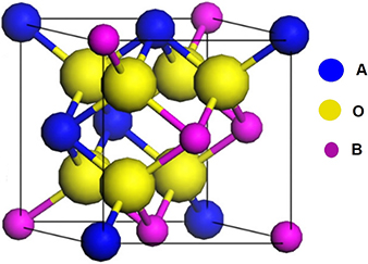
Figure 1.11. One octant part of the pyrochlore structure (A2B2O7). [26] John Wiley and Sons, Copyright 2015.
Download figure:
Standard image High-resolution image1.4.1.4. Layer structured ferroelectrics
In 1949 Aurivillius first synthesized bismuth layer structured ferroelectric (BLSF) materials, hence they are also known as Aurivillius oxides [28, 29]. Bismuth layered ferroelectric materials are used mainly in storage devices and piezoelectric devices in the form of ferroelectric random access memory (FRAM), sensors, and actuators [30]. These materials possess attractive electrical properties due to their low aging and operating voltage, good retaining polarization, fatigue endurance, and high Curie temperature [31].
The Aurivillius oxides or bismuth layer structured ferroelectrics consist of perovskite-like units of TiO2 separated by a layer of bismuth oxide. BLSFs are generally formulated as (Bi2O2)2+ (Am−1Bm O3m+1)2−, where (Am−1Bm O3m+1)2− stands for perovskite blocks interleaved with bismuth oxide layer (Bi2O2)2+ along the c-axis. Ferroelectricity in these compounds is generally due to the cationic displacement along the polar a-axis and the tilting of octahedra around the a- and c-axes [32]. Some of the special properties of Aurivillius oxides are a low switching voltage, good fatigue endurance, and a lead-free chemical composition.
Bismuth based layer structured ferroelectrics are ferroelectric at room temperature and are also environmentally friendly. Their Curie temperature ranges from 300 °C to 700 °C. These materials generally have a high melting point of above 1100 °C and they also possess prospective applications in electronic equipment [31]. Due to all these properties, layered ferroelectrics have a strong potential to replace lead-based ceramics. Examples are Bi2WO6 (m = 1), SrBi2Ta2O9 (m = 2), Bi4Ti3O12 (m = 3), MBi4Ti4O15 (M = Ca, Sr, Pb, Ba) (m = 4), Ba2Bi4Ti5O18 (m = 5), etc.
1.4.2. The classification of ferroelectrics based on properties
Based on their physical and electrical properties, ferroelectric materials are divided broadly into two types: (i) normal ferroelectrics and (ii) relaxor ferroelectrics.
1.4.2.1. Normal ferroelectrics
Normal ferroelectric materials are characterized by the following properties:
- (i)A sharp first- or second-order phase transition at the Curie point (as shown in figure 1.6).
- (ii)The dielectric transition temperature is independent of the frequency of the applied field.
- (iii)The inverse of the dielectric constant (i.e. 1/ε) variation with temperature follows the Curie–Weiss law,
 , where C is the Curie–Weiss constant and To
is the Curie–Weiss temperature.
, where C is the Curie–Weiss constant and To
is the Curie–Weiss temperature. - (iv)The spontaneous polarization drops to zero as the temperature of the crystal is raised to the transition temperature (Tc ).
- (v)A well-defined P–E loop with saturation polarization below Tc and disappear above Tc.
- (vi)A large Pr (remanent polarization).

1.4.2.2. Relaxor ferroelectrics
Relaxor ferroelectrics are characterized by the following characteristics:
- (i)A broad or diffuse phase transition.
- (ii)Significant dependence of the dielectric maximum temperature (Tm ) on frequency (figure 1.12).
- (iii)The 1/ε' versus temperature curve follows the modified Curie–Weiss law (equation (1.7)).
- (iv)Spontaneous polarization of the relaxor ferroelectric becomes zero at a temperature Td (depolarization temperature) that is greater than Tm .
- (v)Slim P–E loops with no sign of saturation near Tm .
- (vi)Weak Pr (remanent polarization).
- (vii)Exhibition of a considerable second-order piezoelectric effect by most of these materials.
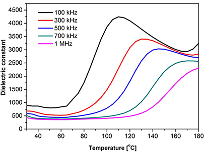
Figure 1.12. Dielectric constant of the relaxor Zr/Nb co-doped barium titanate.
Download figure:
Standard image High-resolution image1.5. Aurivillius oxides
Bismuth layer structured oxides are a family of materials first synthesized by Aurivillius in 1949 [28]. The structure of these Aurivillius phases is described as pseudo-perovskite-type layers interleaved with bismuth oxide layers. There is no particular term used to describe Aurivillius type compounds. Some of the different terminology used for these compounds are bismuth based layered compounds, perovskite based layered structures, layered bismuth oxides, bismuth layer structured ferroelectrics (BLSFs), or other similar names [29]. Most Aurivillius oxides are ferroelectric in nature and these have been the focus of research.
Layered Aurivillius oxide ferroelectrics have a general formula (Bi2O2)2+(Am−1Bm O3m+1)2− [33], where m represents the number of pseudo-perovskite layers alternating between (Bi2O2)2+ layers along the c-axis. The m values can range from 1 to 8. A and B are the two types of cations that enter the perovskite unit. The A-site is relatively large and is occupied by mono-, di-, or trivalent ions such as Na+, K+, Ca2+, Sr2+, Ba2+, Pb2+, etc, or a combination of them, and the B-site is populated by small, highly charged tetra-, penta-, or hexavalent cations such as Ti4+, Nb5+, Ta5+ of the pseudo-perovskite unit. The A-site in bismuth layer structure perovskites and ordered inter growths can accommodate cations with ionic radii ranging from 1.34 Å to 1.61 Å [32]. The B-site can accept cations of ionic radius from 0.59 Å to 0.65 Å. This is a narrower range of ionic sizes compared to perovskites. The lower limit of the ionic radii is determined by the stability of the perovskite layer and the upper limit by the mismatch between the (Bi2O2)2+ and the perovskite layers. The Bi3+ ions occupy two distinct positions, one of which is a 12-fold coordinate site in the perovskite slabs and the other a four-fold site in the (Bi2O2)2+ layers. Table 1.1 shows the family of Aurivillius compounds with a different number of perovskite layers between the Bi2O3 layers.
Table 1.1. Aurivillius oxides with different numbers of perovskite layers between the Bi2O3 layer. Reproduced from [41] with the permission of AIP Publishing.
| m = 1 | m = 2 | m = 3 | m = 4 | m = 5 |
|---|---|---|---|---|
|
|
|
|
|
| m = 1, 2 | m = 2, 3 | m = 3, 4 | m = X |
|---|---|---|---|
|
|
|
|
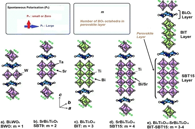
The number of perovskites between the bismuth oxide layers can be odd, even, or a mixture. The value of m influences the ferroelectric properties and structural stability of these materials. Examples of each case are Bi2WO6 (m = 1) and Bi3TiNbO9, SrBi2Nb2O9 (m = 2) and Bi4Ti3O12 (m = 3), and CaBi4Ti4O12 (m = 4), and an example of a mixture of odd and even layered Aurivillius oxide is Bi7Ti4NbO21. In this case, layers with 2 or 3 pseudo-perovskites are alternated with the bismuth oxide layer. Figure 1.13 shows the prototype of the Aurivillius structure as a function of the number of pseudo-perovskite layers.
Figure 1.13. Crystal structures of Aurivillius oxide structures for m = 1, 2, 3, 4 and mixed layers. [34] (2012) Copyright. With permission of Springer.
Download figure:
Standard image High-resolution image
The main difference between layer structured ferroelectrics and perovskite ferroelectrics is that the polarization is not produced by the displacement of the B cation within the oxygen octahedral in perovskites, while polarization is produced by relative shifting of the oxygen octahedral through the a-axis with respect to the [001] bismuth chain in BLSF. They can be divided into three main movements [35, 36]:
- Oxygen octahedral along the a-axis.
- Relative displacements in the opposite direction to the B cations of the perovskite with respect to the octahedral.
- Displacement through the a-axis of the oxygen ions of the Bi2–O3 layer.
Hence, layered ferroelectrics are ferroelectric at room temperature and are environmentally friendly. Their Curie temperature ranges from 300 °C–700 °C. BLSF materials generally have a high melting point above 1100 °C.
In addition, the peculiar crystalline structure of BLSF determines the growth habits for these materials. They also grow in anisotropic shapes, as platelets with the minor dimensions parallel to the c-axis. This is a major drawback for the sintering process to obtain dense bulk ceramics, but favours the grain alignment that allows the texture and the crystal orientation. Some of the special properties of BLSF are a low switching voltage, good fatigue endurance, and a lead-free chemical composition. The high coercive field in BSLF compounds makes them potential candidates for actuators applications. However, due to the high coercive field, depoling by the application of an electrical field becomes difficult, even at room temperature.
An initial study of the symmetry of Aurivillius compounds showed that the structure of these compounds is tetragonal or pseudo-tetragonal [37]. Consequently, researchers showed that the room temperature structure of most Aurivillius compounds is orthorhombic due to small distortion in the highly symmetrical tetragonal (I4/mmm) parent structure. Some Aurivillius compounds (Bi2WO6, Ba2Bi4Ti5O18) belong to the space group B2cb at room temperature, while some others (Bi2BaNb2O9, Bi2SrNb2O9) belong to the space group A2 1 am [38]. The number and type of shifting of perovskite layers are responsible for the low-symmetry of the ferroelectric phase and also for the high-symmetry paraelectric phase. In the family of Aurivillius oxides, the odd number layered compounds crystallize in B2cb, while the even number layered compounds favour A2 1 am symmetry. During the transition from the ferroelectric to paraelectric phase, the modification in the crystal structure of these layered compounds takes place in two ways:
- i.Formation of additional chemical bonds between the cations (bismuth) in the (Bi2O2)2+ layer and anions (oxygen) of the end fragments of the perovskite block at lower temperatures.
- ii.
Currently, Aurivillius phase oxides are considered as significant ferroelectric ceramics due to their high stability, high working temperature (Tc = 550 °C–650 °C) and high operational frequency. Aurivillius oxide ceramics are used chiefly in piezoelectric resonators, as piezoelectric resonators are required to possess a very stable resonant frequency.
References
- [1]Cross L E 1987 Relaxor ferroelectrics Ferroelectrics 76 241–67
- [2]Moulson A J and Herbert J M 1990 Electroceramics (New York: Chapman and Hall) p 41
- [3]Valasek J 1971 The early history of ferroelectricity Ferroelectrics 2 239-44
- [4]Jona F and Shirane G 1962 Ferroelectric Crystals, (International Series of Monographs on Solid State Physics) (Oxford: Pergamon)
- [5]Safari A, Panda R K and Janas V F 1996 Ferroelectricity: materials, characteristics and applications Key Eng. Mater. 122 35–70
- [6]Lencka M M, Oledzka M and Riman R E 2000 Hydrothermal synthesis of sodium and potassium bismuth titanates Chem. Mater. 12 1323-30
- [7]Nye J F 1985 Physical Properties of Crystals: Their Representation by Tensors and Matrices. (Oxford: Oxford University Press)
- [8]Ahmad Z 2012 Polymer dielectric materials Dielectric Material (London: IntechOpen)
- [9]Macdonald J R 1985 Generalizations of 'universal dielectric response' and a general distribution-of-activation-energies model for dielectric and conducting systems J. Appl. Phys. 58 1971–8
- [10]Sinclair D C and West A R 1989 Impedance and modulus spectroscopy of semiconducting BaTiO3 showing positive temperature coefficient of resistance J. Appl. Phys. 66 3850–6
- [11]Duck F 2009 'The electrical expansion of quartz' by Jacques and Pierre Curie Ultrasound 17 197–203
- [12]Dineva P, Gross D, Müller R and Rangelov T 2014 Piezoelectric materials Dynamic Fracture of Piezoelectric Materials (Berlin: Springer) pp 7–32
- [13]Damjanovic D 1998 Ferroelectric, dielectric and piezoelectric properties of ferroelectric thin films and ceramics Rep. Prog. Phys. 61 1267
- [14]Smolenskii G A, Isupov V A, Agranovskaya A I and Popov S N 1961 Ferroelectrics with diffuse phase transitions Sov. Phys.—Sol. State 2 2584–94
- [15]Uchino K and Nomura S 1982 Critical exponents of the dielectric constants in diffused-phase-transition crystals Ferroelectrics 44 55–61
- [16]Smolenskii G A E 1970 Physical phenomena in ferroelectrics with diffused phase transition J. Phys. Soc. Jpn. 28 26–37
- [17]Damjanovic D 1998 Ferroelectric, dielectric and piezoelectric properties of ferroelectric thin films and ceramics Rep. Prog. Phys. 61 1267
- [18]Stemmer S, Streiffer S K, Ernst F and Rüuhle M 1995 Atomistic structure of 90 domain walls in ferroelectric PbTiO3 thin films Philos. Mag. A 71 713–24
- [19]Hyde B G and Andersson S 1989 Inorganic Crystal Structures (New York: Wiley)
- [20]Merz W J 1954 Domain formation and domain wall motions in ferroelectric BaTiO3 single crystals Phys. Rev. 95 690
- [21]Goldschmidt V M 1926 Die Gesetze der Krystallochemie Naturwissenschaften 14 477–85
- [22]Shannon R T and Prewitt C T 1969 Effective ionic radii in oxides and fluorides Acta Cryst. B 25 925–46
- [23]Kumar G R, Savariraj A D, Karthick S N, Selvam S, Balamuralitharan B, Kim H J, Viswanathan K K, Vijaykumar M and Prabakar K 2016 Phase transition kinetics and surface binding states of methylammonium lead iodide perovskite Phys. Chem. Chem. Phys. 18 7284–92
- [24]Gardner J and Morrison F D 2014 A-site size effect in a family of unfilled ferroelectric tetragonal tungsten bronzes: Ba4R0.67Nb10O30 (R= La, Nd, Sm, Gd, Dy and Y) Dalton Trans. 43 11687–95
- [25]De Araujo C P, Scott J F and Taylor G W (ed) 1996 Ferroelectric Thin Films: Synthesis and Basic Properties vol 10 (London: Taylor and Francis)
- [26]Ren X, Zhao M, Wan C, Zheng Y and Pan W 2015 High-temperature aging of plasma sprayed quasi-eutectoid LaYbZr2O7—part I: phase evolution J. Am. Ceram. Soc. 98 2829–35
- [27]Megaw H 1973 Crystal structures. A working approach Studies in Physics and Chemistry vol (Philadelphia, PA: W B Saunders) 10
- [28]Aurivillius B 1949 Mixed bismuth oxides with layer lattices Ark. Kemi. 1 499
- [29]Aurivillius B 1949 Mixed bismuth oxides with layer lattices I. The structure type of CaNb2Bi2O9 Ark. Kemi. 1 463–80
- [30]Subbarao E C 1962 A family of ferroelectric bismuth compounds J. Phys. Chem. Solids 23 665–76
- [31]Newnham R E, Wolfe R W and Dorrian J F 1971 Structural basis of ferroelectricity in the bismuth titanate family Mater. Res. Bull. 6 1029–39
- [32]Frit B and Mercurio J P 1992 The crystal chemistry and dielectric properties of the Aurivillius family of complex bismuth oxides with perovskite-like layered structures J. Alloys Compd. 188 27–35
- [33]Armstrong R A and Newnham R E 1972 Bismuth titanate solid solutions Mater. Res. Bull. 7 1025–34
- [34]Noguchi Y and Miyayama M 2012 Defect control and properties in bismuth layer structured ferroelectric single crystals Lead-Free Piezoelectrics (New York: Springer) pp 405–59
- [35]Rae A D, Thompson J G and Withers R L 1991 Structure refinement of commensurately modulated bismuth tungstate, Bi2WO6 Acta Crystallogr. B 47 870–81
- [36]Thompson J G, Rae A D, Withers R L and Craig D C 1991 Revised structure of Bi3TiNbO9 Acta Crystallogr. B 47 174–80
- [37]Fouskova A and Cross L E 1970 Dielectric properties of bismuth titanate J. Appl. Phys. 41 2834–8
- [38]Ismunandar , Kamiyama T, Hoshikawa A, Zhou Q and Kennedy B J 2005 Structural studies of five layer Aurivillius oxides: A2Bi4Ti5O18 (A = Ca, Sr, Ba and Pb) J. Neutron Res. 13 183–7
- [39]Subbarao E C 1962 Crystal chemistry of mixed bismuth oxides with layer-type structure J. Am. Ceram. Soc. 45 166–9
- [40]Newnham R E, Wolfe R W and Dorrian J F 1971 Structural basis of ferroelectricity in the bismuth titanate family Mater. Res. Bull. 6 1029–39
- [41]Watanabe T and Funakubo H 2006 Controlled crystal growth of layered-perovskite thin films as an approach to study their basic properties J. Appl. Phys. 100 051602