Fundamentals of rechargeable lithium ion and beyond lithium ion batteries
Published December 2021
•
Copyright © IOP Publishing Ltd 2021
Pages 1-1 to 1-24
You need an eReader or compatible software to experience the benefits of the ePub3 file format.
Download complete PDF book, the ePub book or the Kindle book

Permissions
Abstract
A very brief introduction to batteries is provided, with a focus on lithium-ion batteries and the common materials.
In the modern era, transportation is becoming electrified, and portable electronics are widely utilized at work and in daily life. Accompanying this electrification is a quest for batteries with high energy density and long lifetime, and lithium ion batteries are favored because of their combination of high voltage and high specific capacity. However, the inherent chemical complexity and structural hierarchy in battery materials necessitate a deep understanding of both the bulk materials composing electrolytes and electrodes and the interfaces between them. A brief introduction to the fundamentals of batteries is presented here.
Glossary
All-solid-state battery (ASSB): Battery consisting of cathode, anode, and solid electrolyte.
Area Specific Impedance (ASI): Impedance measured for charge and discharge pulses. See equation (1.9) for definition.
Coulombic efficiency: The ratio of discharge capacity to the charge capacity of the preceding cycle.
Crystal field stabilization energy theory (CFSE): Depicts the stability that results from placing a transition metal ion in the crystal field generated by a set of ligands.
Density of states: In solid state physics and condensed matter physics, the proportion of states that are to be occupied by the system at each energy.
dQ/dV: Differential capacity versus differential voltage; depicts the plateau information associated with phase equilibria information regarding the intercalation and deintercalation of Li+ (or other active ions).
dV/dQ: Differential voltage versus differential capacity; depicts the phase transition (the voltage drop/increase in the voltage profile).
EV: Electric vehicle.
Faraday's Law: A statement of the relationship between the current that runs through an external circuit and the quantities of active materials that are consumed/produced in the ensuing electrochemical reaction.
Gr: Graphite anode.
Gr-Si: A composite anode consisting of graphite (Gr) and silicon (Si).
Highest Occupied Molecular Orbital (HOMO): The highest occupied molecular orbital in frontier molecular orbital theory, usually manifested as the oxidation potential.
Hybrid Pulse Power Characterization (HPPC): A test profile specifically designed to elicit the dynamic power capability of a Li-ion battery for electric vehicles (EVs) at a given state of charge and aging status.
Li+ inventory: Total amount of cyclable Li+, usually referring to a full cell setup using a lithiated transition metal oxide as the cathode and graphite as the anode, with all cyclable Li+ inventory coming from the cathode.
Lithium cobalt oxide (LiCoO2 or LCO): A layered cathode, consisting of lithium, cobalt and oxygen elements, that was widely used in volumetrically dense lithium ion batteries.
LMR: Lithium manganese rich
Lowest Unoccupied Molecular Orbital (LUMO): The lowest unoccupied molecular orbital in frontier molecular orbital theory, usually manifested as the reduction potential.
NMC: Lithium nickel–manganese cobalt oxide cathode materials.
OTMS: Trimethylsilyl oxyl group, with a molecular formula of −O−Si(CH3)3.
P(OTMS)2 F: Bis(trimethylsilyl) fluorophosphate, with a molecular formula of P(−O−Si(CH3)3)2F.
P(OTMS)3 : Tris(trimethylsilyl) phosphite, with a molecular formula of P(−O−Si(CH3)3)3.
P(OTMS)F2 : Trimethylsilyl bisfluorophosphite, with a molecular formula of P(−O−Si(CH3)3)F2.
RE: Reference electrode.
Solid–electrolyte interphase (SEI): A layer, consisting of both organic and inorganic materials, that exists as the medium between two surfaces; historically, the SEI in lithium ion batteries consists of a mosaic-like array of 3-D materials, with components including Li2CO3, LiF, RCOOLi, R'OLi (the R' is used to represent a different alkyl group than the previous R group) and many others [1].
State of charge (SOC): Level of charge of an electric battery relative to its capacity.
Transition metal oxides (TMOs): Prevalent cathode materials that consist of transition metals and their oxides.
List of symbols
| concentration of species I, mol m−3 | |
| molecular diffusivity of species I, m2·s−1 | |
| EF | Fermi level |
| F | Faraday's constant, 96 485 C per equivalent |
| I | current density, A m−2 |
| molar flux of species I relative to stationary coordinates, mol m−2 s−1 | |
| NAVO | Avogadro's number |
| molar flux of species I relative to stationary coordinates, mol m−2 s−1 | |
| q | fundamental unit of charge |
| R | universal gas constant, 8.314 J mol−1K−1 |
| T | temperature, K or °C |
| mobility of ion, m2 mol J−1s−1 | |
| Voc | open-circuit voltage |
| charge number | |
| α | Debye constant for solvent, (kg mol−1)1/2 |
| β | symmetry factor, unitless |
| activity coefficient, unitless | |
| surface overpotential, V | |
| μc | potential of cathode, V |
| μa | potential of anode, V |
| v | velocity, m s−1 |
| ϕ | potential, V |


Since the emergence of Sony's commercial lithium ion battery in 1991, society has embraced new technologies ranging from battery-operated power tools and portable consumer electronics such as smart phones to electric vehicles (EVs). It was no surprise that the 2019 Nobel Prize in Chemistry was jointly awarded to John B Goodenough, M Stanley Whittingham, and Akira Yoshino for 'the development of lithium ion batteries (LIBs).' [2]
There are still hurdles to overcome before EVs capable of a long driving range (200 miles and above) on a single charge, and other more far-reaching possibilities, such as Unmanned Aerial Vehicles, become mass-market technologies. A few of the dominant hurdles are achieving higher energy density (of cathodes, anodes and electrolytes) for: longer mileage and usage time; a long lifetime; low cost; pathways to reuse, recycling, and reduction of carbon footprint; and the ability to withstand extreme temperature changes.
The following text is divided into three sections. The first section is an introduction to batteries for researchers from all scientific disciplines; the second section describes current study areas in more detail, centering on battery components; and the last is a brief section of conclusion.
1.1. Introduction to batteries
Rechargeable lithium ion batteries and beyond lithium ion batteries are attracting more attention recently. Conventional lithium ion batteries (LIBs) are rechargeable electrochemical energy storage devices based on the intercalation mechanism (figure 1.1): upon discharging, through the movement and intercalationof Li+ ions into the cathode, a concomitant electron moves into the cathode and generates current to satisfy the charge balance. Since the battery is inside a closed circuit, the electron will go through the circuit to the anode side, and one electron will come out together with deintercalation of a Li+. The process is reversed for the charging process. Overall, batteries are relatively low in power generation (pulse) and high in energy storage. For processes such as braking or accelerating in EVs, assistance in power generation is required, as a large current is passed through the system during these processes.

Figure 1.1. Schematic representation of basic components of a classic intercalation lithium ion battery with a transition metal oxide cathode, a graphite anode, and a nonaqueous electrolyte.
Download figure:
Standard image High-resolution imageOther than materials that use the intercalation mechanism, cathodes for batteries can also be of conversion materials, such as in the cases of the low-cost/high-energy-density Li–S and Li–air batteries. Conversion reactions can be expressed in the following equation for a conversion type material of M:

1.1.1. Lithium ion batteries
1.1.1.1. Fundamentals
As shown in figure 1.1, a conventional intercalation battery setup includes three major components: cathode, anode (a graphite anode, or Gr, is used as an example), and electrolyte. An example of an intercalation cathode material is lithium cobalt oxide (LiCoO2), or LCO, which is widely adopted for portable electronics. Because cobalt resources are limited and geopolitical tensions arise from cobalt mining, current research is devoted to development of transition metal oxides (TMOs) that are low in cobalt but high in nickel and manganese. However, because of the high volumetric energy density of LCO, it is still favored over other TMOs for portable electronics. EVs, on the other hand, are more forgiving with respect to volumetric energy density, and the emphasis there is on high gravimetric energy density and cost effectiveness.
The anode for lithium ion batteries is usually graphite due to its low potential, safety, and high specific capacity. More specific details are given in section 1.2.
An easy way to characterize a nonaqueous electrolyte is through its electrochemical window, a practical value that can be associated with the theoretical quantity Eg. The traditional view is that the Lowest Unoccupied Molecular Orbital (LUMO) is associated with cathodic stability, the Highest Occupied Molecular Orbital (HOMO) is associated with anodic stability, and the difference between LUMO and HOMO characterizes the electrolyte's electrochemical window. However, it is better to explain the electrochemical window in parallel with the transition-metal energy band, as many of the physical and chemical phenomena in batteries are related. The potentials of the cathode (μc) and anode (μa) are determined by their Fermi energies (EF) in the itinerant-electron band, and the μc and μa consequently determine the cell's open-circuit voltages Voc = (μa−μc)/e. As shown in figure 1.2, the μc and μa should ideally be within the bracket of LUMO and HOMO. However, in most LIBs, because of the low reduction potential of the Gr, 0.1 V versus Li/Li+ (all voltages subsequently cited in this paper will use Li/Li+ as the reference), almost no electrolytes will have a higher LUMO than lithiated graphite.

Figure 1.2. Schematic of the density of states (DOS) of LiCoO2, in which the Fermi energy levels of anode and cathode (EFA and EFC) are represented by horizontal dotted lines.
Download figure:
Standard image High-resolution imageThe practical way to expand HOMO and LUMO is to have a solid–electrolyte interface (SEI) that successfully blocks the reduction of electrolyte in contact with the anode, and yet effectively transports the Li+ ions.
In a typical LIB with a TMO cathode and a Gr, different electrochemical reactions take place at the cathode and the anode simultaneously. The general Faraday's Law can be used to calculate the theoretical capacity of electrode materials; it depicts the relationship between the current that runs through the external circuit and the amount of the corresponding active materials that are consumed/produced in the electrochemical reaction. For example, in a typical graphite reduction,

Using Faraday's Law, F = qNAV: where q is the fundamental unit of charge, and NAVO is Avogadro's number, Faraday's constant F has a value of 96 485 C mol−1. The molecular weight of C6 (graphite) is 72 g mol−1, and the theoretical capacity of graphite can be calculated as


From this example, a general formula can be deduced for the calculation of a theoretical capacity:

where z is the number of electrons generated per molecule.
1.1.1.2. Electrochemistry
The fundamentals of electrochemistry are covered well in the classical electrochemistry books. A recent book by Fuller and Harb also offers both the basics and in-depth study materials for topics such as thermodynamics, electrochemical kinetics, and transport, with examples of how each concept is used [3]. We encourage readers to refer to those books for an understanding of the basics. Three fundamental equations, the Debye–Hückel equation (activity coefficient), Butler–Volmer equation (electrochemical kinetics), and Nernst–Plant equation (transport properties), are given here for the readers' reference:


Three parameters are identified as the important criteria for measuring the performance of a battery: coulombic efficiency, specific capacity, and capacity retention. Recently, more detailed studies have been implemented to get a deeper understanding of the operation of a battery, mainly addressing: (1) the individual voltages of cathodes and anodes using a reference cell; (2) detection of lithium slippage; (3) application of dV/dQ and dQ/dV; and (4) impedance studies on both the anodes and cathodes.
Figure 1.3 illustrates the overall voltages of the batteries, as well as the individual voltages experienced on the cathode and anode. The method commonly used to measure the individual voltages is to use a third Li metal reference electrode that can either be made in-house or purchased. The same concept can be adapted for measurement of individual impedance on the cathode and anode. Interestingly, in an NMC//Gr cell, the initial cell voltage after assembly is ~0 V; however, through the initial charge pulse (for example, a current of 1.5 C rate), the cathode stays at a relatively stable voltage of 3.7 V [4].

Figure 1.3. (a) Schematic representation of a basic coin-cell setup. (b) A custom reference cell for measurement of both in situ potential and impedance versus a reference. (c) A representative voltage profile of a cathode and anode that is measured from a reference cell.
Download figure:
Standard image High-resolution imageA typical coin-cell anatomy is shown in figure 1.3(A). A more advanced version, a so-called reference cell, is shown in figure 1.3(B). This type of cell consists of two 20.3-cm2 electrode disks separated by two layers of a 25-μm-thick microporous separator (Celgard 2325). The unique feature of this reference cell is the Cu–Li alloy wire used as a reference. Lithium metal was plated in situ onto the tip of this thin (25-μm-dia.) Cu wire to form a microprobe reference electrode (RE). Only a 2- to 3-mm portion of this wire was exposed to the electrolyte and coated with Li; the remainder was insulated by a polyurethane coating. The Cu wire was lithiated at 5 μA for 6 h, with the cathode as the source of lithium. The advantage of such a Li–Cu alloy wire is that it provides an accurate reference for both the potential and the impedance. A typical compiled voltage profile consisting of the anode potential, the cathode potential, and the full cell potential is shown in figure 1.3(C).
Cycling protocols (determining which electrochemical condition the cells will experience) are also crucial for battery performance evaluation and mechanism diagnosis. For example, a comprehensive cycling protocol was implemented at Argonne National Laboratory to impose harsher conditions than normal cycling, and triplicate cells were used to provide for repeatable examination of the cells [5]. In general, the cycling procedure can be divided into four electrochemical steps: formation, preparation, HPPC (Hybrid Pulse Power Characterization), and aging. The formation step consists of five slow C/20 cycles to ensure the formation of a robust SEI layer. Preparation consists of a slow C/10 cycle. HPPC cycles are specifically designed to mimic the EV operating conditions occurring at the 'accelerating' or 'braking' stages, with large pulses going through the cell and the impedance recorded at different states of charge (SOCs). Over the course of 119 cycles, periods of slow C/20 cycles were inserted before each of the 20 fast C/3 cycles (classified as the 'aging' step) so that capacity could be indicated with less influence from the impedance. The HPPC segments were purposely reinstituted before each of the 20 cycles of the C/3 aging. A rather aggressive cycling protocol was used: the galvanostatic charge (constant current) was followed by a constant voltage hold of 3 h. Through a standard cycle package of 119 cycles, information is obtained with respect to (1) the Area Specific Impedance (ASI) change during the cycling [6]; (2) aging, reflecting the capacity retention (through both the major C/3 cycles and periodic C/20 cycles); and (3) dQ/dV, from the C/20 cycles [5]. ASI can be measured through the HPPC cycles using the following equation, with the parameters Vt , V0, t0, and t1 shown in figure 1.4(b) [6]:

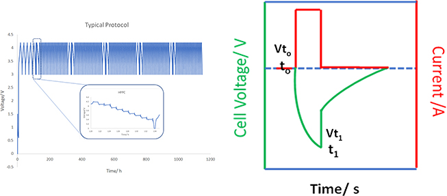
Figure 1.4. (a) Typical protocol (voltage versus time) for testing a full cell consisting of a graphite anode and TMO cathode; the cutoff voltages are 3 and 4.2 V, and the inset shows the voltage profile of the HPPC cycle. (b) Schematic representation of the cell voltage and current for the ASI measurement.
Download figure:
Standard image High-resolution imageAnother key concept in battery research is the slippage of voltage. The original voltage profiles for a representative NMR//Gr cell is shown in figure 1.5(a), the Vc0 at 4.22 V and Va0 at 0.12 V, once the cycled electrodes reach the charge voltage and in the absence of the reference cell, the voltage reflected through the cell potential is the difference between the positive and negative electrode (Vc = Vc−Va). Using an NMC//Gr-Si cell as an example, the slippage of capacity results in a large increase in the electrode potential of the anode. In one scenario where no Li+ inventory loss and no cathode degradation occurs, the endpoint voltages and discharge/charge profiles of the cathode and the anode will remain the same. However, using the NMC cathode as an example, when a charge cutoff of 4.1 V is maintained, as the cathode capacity decreases (anode capacity slips to the right), the anode voltage will slightly increase (Va1 = 0.15 V). In the next cycle, the cathode needs to reach a higher individual voltage to maintain the Vc1−Va1, resulting in higher polarization of the cathode (Vc1 > Vc0). The voltage profile of graphite is featured with plateaus at ~ 120 mV and 90 mV, and loss of the capacity when cells are cycled at the same upper cutoff voltages will push the voltage in the anode to the right with respect to the cathode. For example, in figure 1.5(b), as the cell ages, the capacity decreases, as denoted by the gray area of Li+ inventory loss, resulting in the increase of anode voltage at 0.15 V. As shown in figure 1.5(c), when a Li+ gain occurs in the anode side, slippage towards the right of the anode is observed (Va2 = 0.09 V).

Figure 1.5. Schematic representation of the slippages in the electrodes. (a) the absence of capacity fade, electrode potentials remain stationary (a), while net capacity loss or gain causes the anode to shift to the right (b) or to the left (c), respectively, relative to the cathode. As in figure 1.1, capacity loss leads to higher electrode potentials at the same full-cell voltage cutoff of 4.1 V. Reproduced from [7].
Download figure:
Standard image High-resolution image1.1.2. Beyond lithium ion batteries
'Beyond lithium ion batteries' refers to technologies that do not revolve around the traditional rocking-chair Li intercalation–deintercalation mechanism; instead, they comprise frontier technologies such as Na and K ion batteries, lithium–air batteries, batteries with multivalent ions (where the mobile charge carrier has a valence number of 2 or more), lithium metal batteries, and all-solid-state batteries (ASSBs) [8].
The electrochemistry and fundamentals of beyond lithium ion batteries, including SEI formation and intercalation mechanisms for cathodes, resemble those of the LIBs and will not be described here. The important features and characteristics of beyond lithium ion batteries can be found in several recent reviews and perspectives [8, 9].
1.2. Basic components of batteries
1.2.1. Cathodes
As shown in table 1.1, intercalation cathodes can be loosely categorized into layered materials (LCO, NMC, LMR-NMC), polyanion materials (LiCoPO4, LiFePO4), and spinel materials (LiMn2O4, LiNi0.5Mn1.5O2), and conversion materials on the basis of their framework structures. The structures of the former three materials are shown in figure 1.6. The emphasis here will be on the layered materials because of their commercialization as cathode materials in the EV market [10, 11].
Table 1.1. Specific capacity and voltages of some common cathodes for lithium ion batteries.
| Structure | Cathode | Specific gravimetric capacity (mAh g−1) | Volumetric capacity (theoretical/practical, Wh l−1) | Average potential (V) | References |
|---|---|---|---|---|---|
| Layered | LCO | 273/145 | 1363/550 | 3.8 | [11] |
| LiNix Mny Coz O2 | 273/ | 1333/600 | 3.7 | [11] | |
| LMR-NMCLi1.2Ni0.4Mn0.4O2 (=0.5Li2MnO3–0.5LiNi0.5Mn0.5O2) | 375/250–280 (1.2 li extraction) | >1000 | 3.7 | [12] | |
| Spinel | LiMn2O4 | 148/120 | 596 | 4.1 | [11] |
| LiNi0.5Mn1.5O2 | 147 | 4.9 | [11] | ||
| Polyanion | LiCoPO4 | 167/125 | 510 | 3.7 | [11] |
| (olivine) | LiFePO4 | 170/165 | 589 | 3.4 | [11] |
| Conversion | S | 1675 | 2.8 | [13] | |
| O2 | 3840 | 3.1 | [14] |

Figure 1.6. The crystal structures of layered LiCoO2 (one-dimensional Li+ transport), spinel LiMn2O4 (two-dimensional Li+ transport), and olivine LiFePO4 (three-dimensional Li+ transport).
Download figure:
Standard image High-resolution image1.2.1.1. Layered materials
Nowadays, LCO is still the cathode of choice for portable electronics because of its high volumetric energy density. However, the dominant usage of LCO raises concerns over the geopolitical and environmental aspects of cobalt mining. The desire for a reduction in the cobalt component, and for other characteristics including higher voltage, high rate capability, long cycle life, and high energy density, has motivated research on cathodes for LIBs. Concerted efforts to improve the performance of LCO have included structural modifications to improve both its stability and resistivity, and the modification of the electrolyte–electrode interface to reduce cathode impedance rise [15]. In contrast to the high compact density of LCO (4.05–4.15 g cm3) [16], NMC materials only have a compact density in the range of 3.1–3.6 g cm3. Despite the theoretical capacity of 273 mAhg−1, only half of the Li+ inventory in LCO is practically usable with a cutoff voltage of less than 4.2 V versus Li/Li+, which is necessary for maintaining structural stability over prolonged cycling [15, 17–19]. Recognized as one of the first layered materials through the work of Goodenough [20], LCO has a layered α-NaFeO2 structure, featuring a rhombohedral structure with an R3m space group, with the oxygens arranged in a cubic close-packed network and lattice constants of a = 2.816 Å and c =14.052. Li and Co3+ alternate in the (111) planes to form CoO6 and LiO6 octahedra. The CoO6 octahedra share edges and form CoO2 sheets, separated by sheets of octahedral Li [21]. During delithiation, the structure first undergoes expansion of the c axis due to the loss of Li and weak Van der Waals expulsion between the CoO2 sheets; however, further delithiation (to Lix CoO2 with x < 0.5) would be detrimental, resulting in structure collapse.
Other layered TMOs with a lower cobalt content include NMC materials with a general formula of LiNix Mny Coz O2 (where x + y + z = 1), including the high-nickel cathodes that are under industrial consideration for the realization of higher-energy-density batteries of 800 Wh kg−1 at the cell level.
Three other severe problems have been noted with cycling LCO at high voltages [22]: (1) the interface between the delithiated LCO and the electrolyte is unstable. As shown in figure 1.2, the thermodynamic stability window of the electrolyte should surpass the electrode electrochemical potential of both the cathode and the anode. As LCO is cycled to a higher voltage (> 4.45 V), the deterioration of electrolyte is exacerbated, with the formation of a resistive passivation layer and a large impedance rise. Coating or doping with oxides such as Al2O3 [23] or ZrO2 [24] reduces the contact area between LCO and electrolyte and improves the performance under high voltages. (2) The Co dissolution increases with a higher cutoff voltage (> 4.2 V), together with the loss of O (peroxo species of O2, O2 −). The delithiation process lowers the Fermi level of Co3+ until the Co 3d orbital overlaps with the O 2p band (figure 1.4) and facilitates peroxo evolution [25, 26]. Evolution of these peroxo species causes irreversible surface decomposition and phase transformation of the cathodes, which eventually leads to capacity fade. (3) Degradation of other components such as the binders and the separators occurs, and the consequent detachment of cathode particles can lead to capacity loss.
1.2.2. Anodes
Anodes are important because of the possible high volumetric energy density associated with utilization of metal anodes such as Li, Mg and Ca. The reduction potentials of these metal anodes are compared with those of the traditional Gr in table 1.2. This chapter does not intend to give a complete discussion of all possible anodes, but will focus on the important characteristics of certain anodes, which are categorized loosely based on application: (1) graphites, (2) lithium metal anodes, and (3) other metal anodes, including alloys.
Table 1.2. Common anodes with specific gravimetric capacity and volumetric capacity.
| Anode | Specific gravimetric capacity (mAh g−1) | Volumetric capacity (mAh c.c.−1) | Average potential (V) | References |
|---|---|---|---|---|
| Graphite (Gr) | 360 | 570 | 0.1 V | [27] |
| Silicon | 4200/3154 a | 800 | 0.06–0.12 V | [27, 28] |
| Lithium | 3828 | 1700 | 0 V | [29] |
| Sodium | 1165 | 0.1 V | [30] | |
| Magnesium | 2233 | 3833 | 0.6 V | |
| Calcium | 1340 | 2073 | 0.1 V |
1.2.2.1. Graphite
In the context of battery materials, graphite refers to 'graphitic carbon,' with a structure consisting of a hexagonal network of carbon atoms lacking crystalline ordering in the c direction. A typical crystalline structure of graphite is illustrated in figure 1.7, with alternating A and B layers consisting of sp2 hexagonal array of carbon atoms. Upon lithium intercalation, each C6 can accommodate one Li+ atom.

Figure 1.7. Schematic representation of the layered structure of graphite and how Li+ intercalates between the graphite layers.
Download figure:
Standard image High-resolution imageThe basal planes, referring to the hexagonal C6 planes, have a spacing (d002) of 3.35 Å, about twice that of the Van der Waals distance for carbon atoms. Graphite displays a non-perfectness, and the basal planes demonstrate less reactivity than the edge planes. Upon lithiation, the Li+ intercalates through the edge plane and imperfect basal plane, with three distinctive plateaus at 208, 116 and 83 mV (figure 1.8(c)). To circumvent the reactivity of the edge plane, SEI formation enables further intercalation at the expense of consumption of Li+ inventory.
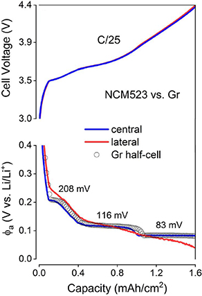
Figure 1.8. Schematic representation of the three distinctive plateaus observed upon Li+ intercalation: the voltage profile of a full cell consisting of an NCM 523 cathode and a Gr was used as an example. Cell voltages and anode potentials (φa) were measured at C/25 using the RE arrangements. Graphite staging potentials determined using the centrally placed RE are indicated in the plot. The potential of a Li//Gr half-cell charged at a C/110 rate (gray open circles) is overlaid for comparison (from [31]).
Download figure:
Standard image High-resolution image1.2.2.2. Li metal anodes
With the development of Li–S batteries and ASSBs, lithium metal anode research has demonstrated the potential for reaching the high theoretical gravimetric capacity of 3860 mAh g−1. However, the promise of Li metal anodes is accompanied by serious issues, such as the extreme electropositivity of Li metal and its resulting reactivity with almost all organic components, as well as the large interfacial resistance of SEIs consisting of LiF, Li2CO3, ROLi, and R'COOLi [1].
1.2.2.3. Other metal anodes
The prevalent challenges associated with the application of metal anodes include particle pulverization, unstable SEI, and impedance rise from electrolyte decomposition on the interfaces. The large ionic radii of the relevant metal ions (Na+, 1.02 Å; K+, 1.38 Å; Mg2+, 0.72 Å; Ca2+, 1.00 Å [32]) and the charge density can also cause difficulty with intercalation into the cathode lattices.
Among the potential metal anodes for batteries, silicon has been researched extensively in both academia and industry. Co-utilization of graphite and silicon is a common practice to alleviate the issues associated with using Si particles alone, and can increase the specific capacity [27].
The concerns about cost and long-term sustainability of Li resources also demand development of alternative low-cost and sustainable energy storage systems. Novel research, targeting energy based on low-cost and naturally abundant elements, is focusing on using Na and K. The abundance and low price of these elements enable the possibility of sustainably produced, low-cost batteries based on Na+ and K+ ions [8, 33].
Cathode materials utilizing Na+ and K+ intercalation that have been explored include layered TMOs, polyanionic compounds [33], and Prussian-blue analogs (Ax MA[MB(CN)6]y , where A = a combination of Li and Na, and M is a transition metal: Fe, Mn, Co, Ni, Cu, etc). Compared with their Li analog, the large size of Na+ and K+ can be of benefit for slowing the mobility and disordering of the transition metal. Cathodes with the layered structure of O3−NaNi0.5Mn0.5O2 can show good cycling stability, with the major issues arising mostly from the delithiated state with low Na/K content [8].
1.2.3. Electrolytes
For the sake of convenience, electrolytes used in LIBs and in beyond lithium ion batteries are discussed separately.
1.2.3.1. Lithium ion batteries
Without Yoshino Akira's introduction of the combination of Gr and carbonate (a unique compound with an −O−C(=O)−O moiety that is prone to react with underpotential Li to generate a SEI and impart extra thermodynamic stability), it would be hard to imagine developing the compositions of today's electrolytes. In particular, ethylene carbonate is responsible for formation of a stable SEI on the surface of a Gr. The success of the Gr anode in LIBs has also revealed another truth: the electrolyte has unique capabilities to modify the interlayer surface.
Despite the enormous progress researchers have made regarding cathodes and anodes, the fraction of LIB research devoted to electrolytes seems relatively small. The discussion of electrolytes below will center on the development of (1) lithium salts; (2) additives; (3) solvents; and (4) special applications involving extreme temperature, fast-charging conditions, and non-flammability.
1.2.3.1.1. Lithium salts
Lithium salts are essentially used for the purpose of transporting Li+ under chemically and electrochemically active conditions. The electrolyte environment needs to be compatible with current collectors, cathodes—especially when in a delithiated state, with many energetic active sites to cause decomposition—and anodes in a lithiated state with a potential close to the Li redox potential (~ 100 mV).
The most common lithium salt used in commercial LIBs is LiPF6, which seems to provide the best combination of ionic conductivity, electrochemical stability, stability with respect to the current collector (a safety criterion), and overall LIB performance. The basic properties of LiPF6 and several other common lithium salts, such as LiTFSI (Li(CF3SO2)2N), LiAsF6, LiClO4, LiBF4, and LiCF3SO3, can be found in the literature [34]; these include such properties as ionic conductivity, ionic radii, temperature, and stability towards both Cu (the anode current collector) and Al (the cathode current collector). Relatively new salts—LiN(SO2C2F5)2 (LiBETI) [35], lithium bis (oxalate) borate (LiBOB) [36], LiPF3(C2F5)3 (LiFAP) [37], lithium 4,5-dicyano-2-(trifluoromethyl) imidazolide (LiTDI) [38], lithium 4,5-dicyano-2-(pentafluoroethyl) imidazolide (LiPDI), and lithium bis(fluorosulfonyl)imide (LiFSI)—are also available through exploratory design and syntheses, although their compatibility with coin cells and their electrochemical stability are still a matter of debate.
Below, the chemistry of LiPF6 will be discussed in detail with respect to its reactivity towards H2O [39] (an unavoidable impurity), solvent [40], and additives such as tris(trimethylsilyl) phosphite [41].
The cascading hydrolysis of LiPF6 is illustrated in scheme 1.1. Overall, the reactivity of LiPF6 with water is detrimental, leading to formation of both HF and oxyfluorophosphoric acid, which corrodes the cathodes and causes crossover of transition metal species (Mn2+); these species cause the poisoning of the anode, leading to an electrocatalytic reduction of Li+ inventory and capacity loss. Recent studies of hydrolysis of LiPF6 under high voltage suggest that the detrimental catalytic effects of high voltage are much worse, with the majority of the hydrolysis products coming from the reaction between PF6 − anion and H2O under voltages above 4.5 V.

Scheme 1.1. (Left) the hydrolysis cascade reaction between LiPF6 and H2O. (Right) the proposed reaction of PF6 − anion and H2O under high voltages [42].
Download figure:
Standard image High-resolution image1.2.3.1.2. Additives
Additives are designed for task-specific applications such as anode SEI formation, cathode CEI formation, flame retardation, and other unique applications including fast-charge and extreme-temperature applications. The Dahn group, as well as Argonne National Laboratory researchers, have long been developing both singular and combinatorial additives [43, 44].
The reactivity of LiPF6 with tris(trimethylsilyl) phosphite (TMSPi) was discovered by the Winter group [41]. As shown in scheme 1.2, the reaction involves an astounding F–O exchange between the P−F bond and the P−O−TMS bond, resulting in formation of three compounds: P(OTMS)2F, P(OTMS)F2 and PF3. The intermediate compound O=P(−F)2−O− can also react with P(OTMS)3 to generate P(OTMS)2F and O=P(−F)2−OTMS; note the presence of an extra O=P in the latter compound. Overall, a spontaneous cascading reaction is observed with aging, with little control of either the speciation or concentration (figure 1.9). In general, it is predicted that P(OTMS)3 will show a consistent decrease with time, while both the P(OTMS)2F and P(OTMS)F2 intermediates will show an initial increase before reaching a maximum concentration, followed by a decrease. The final product PF3 appears last in the reaction and is expected to show a steady increase until the original P(OTMS)3 is totally consumed.

Scheme 1.2. Spontaneous reactivity of TMSPi with LiPF6. The F–O exchange is emphasized with an underscore.
Download figure:
Standard image High-resolution image
Figure 1.9. Schematic representation of species evolution with time for the reaction of the additive TMSPi with a solution of LiPF6 in carbonate solvent.
Download figure:
Standard image High-resolution imageThe control of the spontaneity of the LiPF6 reactivity, however, has been showcased in our group recently by a unique in situ method for formation of cathode-protective additives with structures identified as lithium oxyfluorophosphates (2a and 2b), as illustrated in scheme 1.3. These in situ reactions take advantage of the reactivity of LiPF6 with the bis(trimethylsilyl) esters 1a and 1b, and a series of extremely moisture-sensitive tetrafluorophosphates can be easily obtained at a nearly 100% yield in the solution (scheme 1.4) [45]. In contrast to the reaction in scheme 1.2, there is only one designated product from the reaction between LiPF6 and bis(trimethylsilyl)ester. As discussed by Yang et al, the strain of the carboxylate linker in the tetrafluorophosphate is important: strong preference goes to the 5-membered and 6-membered rings because of the lesser ring strain and torsional strain. A similar protective effect on the cathode surface was also discovered: a 6-membered ring was found to have a superior effect on the reduction of impedance rise in an NMC//Gr full cell [45].

Scheme 1.3. In situ synthesis of anions 2a and 2b from molecular precursors 1a and 1b.
Download figure:
Standard image High-resolution image
Scheme 1.4. Synthesis and structural formulas of hypothesized monoanion products.
Download figure:
Standard image High-resolution imageLIBs for industrial applications require a combination of excellent thermal stability, wetting capability, and SEI formation capability, resulting in the presence of many additives and co-solvents of propionate compounds [46]. The additives in commercial LIBs are targeted for different applications and can be loosely classified as anode additives, cathode (interfacial) additives, overcharge protection, and alloy additives [43, 47]. Some common additives are shown in figure 1.10.

Figure 1.10. Exemplary structures of additives used in lithium ion batteries.
Download figure:
Standard image High-resolution image
Despite the large number of additives that are already available, new additives and uses for those additives are continuing to be invented [48].
1.2.3.1.3. Solvents
The solvent component for LIBs has not been changed significantly since its invention in 1991 by Sony. Owing to the bulk amount of solvent compared with other components in electrolytes (salts and additives), the following properties of solvents are usually considered most important: high electrochemical stability towards cathodes and anodes (graphite), high transport rate, good wetting ability, and good thermal properties (ability to function reasonably well in a wide temperature range). Despite the critical role that ethylene carbonate plays in formation of the SEI, this component has problems such as low electrochemical stability and large impedance rise [49]. The use of co-solvent is a strategy that can significantly change the Li+ ion transport speed, wetting capability, and, potentially, electrochemical properties. Issues with fast charging and temperature intolerance usually relate to the extremely slow transport of Li+ relative to the fast electron movement; Li plating occurs as a result of overpotential buildup and slow solid-state Li+ transport. To achieve fast charging (usually with EV applications in mind) and the lofty goal of 80% capacity retention within 15 min, solvents have been sifted through a myriad of criteria to better support Li+ ion transport [46]. Esters, albeit possessing low electrochemical stability, have found applications in industrial-scale electrolyte formulation for LIBs because of several favorable properties, including high ionic conductivity, low viscosity, and good wetting properties. Using esters as an example, one can compare the performance of co-solvents with respect to the following criteria: electrochemical window, relative permittivity, viscosity, self-discharge voltages, discharge capacity at 40 °C from 3.0 to 4.2 V, coulombic efficiency, gas generation during formation, storage, and stability at 60 °C 500 h−1. Several new categories of co-solvents, including formates and nitriles, have proven to be beneficial for fast-charging applications. This discussion is not meant to provide an inclusive list of all the chemicals that have been studied; however, it is representative enough to encourage more exploration, especially centering on the categories of nitriles and esters (propionates and formates).
1.2.3.1.4. Special applications: extreme-temperature, fast-charging, and flame-retardant electrolytes
Task-specific electrolytes can be designed for special applications: solvents, salts, and additives are all important for these non-conventional or extreme applications. Additives such as high-boiling-point nitrile (HTCN) are important in an industrial setting to allow electrolytes to tolerate the high-temperature formation and storage processes that industrial cells usually go through. Nitrile compounds (propionitrile or butyronitrile) can also enable low-temperature operation of energy storage systems in the range of −20 °C to −110 °C [50]. High-temperature operation of LIBs requires appropriate choices of both electrolytes (solvents, salts and additives) and cathodes, using advanced thermal analysis methods such as differential scanning calorimetry and accelerating-rate calorimetry, and in situ gas analysis [51] via differential electrochemical mass spectroscopy.
1.2.3.2. Beyond lithium ion batteries
1.2.3.2.1. Lithium metal batteries
The electrolytes used for lithium metal-based batteries, including Li–air batteries and Li–S batteries, are usually LiTFSI dissolved in an ethereal solvent. The advantages of Li–S batteries include the high theoretical specific energy of sulfur (2600 W h kg−1), its natural abundance (3.96%–4.77%), and low cost ($50 ton−1). However, several well-known problems associated with Li–S batteries prevent their commercial application: the shuttling of soluble polysulfide species, the poisoning of polysulfide at the lithium metal anode, and low loading of the active materials on the cathode part. Since a coin-cell setup can lead to misleadingly 'good' performance of Li–S batteries, with flooded cells leading to an unlimited Li+ inventory, Li–S batteries have been vigorously tested in a pouch cell, with controlled Li+ inventory and electrolyte amount (electrolyte/sulfur ratio) [13].
Li–air batteries and Li–oxygen batteries, despite their promise, have practical issues, including kinetic issues manifested as high overpotential and low discharge voltages, and the detrimental interference of persistent impurity components in the air (CO2, H2O, N2, etc). A materials-to-system analysis of mass, volume, and cost values reveals that Li–air batteries are unlikely to be useful in EVs because of the large penalty resulting from utilization of a gaseous reactant [29]. Such a systems-level engineering simulation also identifies Si/NMC as a moderate-risk pathway to achieve commercial application in EV markets. The electrolytes for Li–air batteries consist of a lithium salt in a variety of solvents (carbonates, dimethylsulfoxide, ethers, etc) [52].
1.2.3.2.2. Multivalent ion batteries
Multivalent ion batteries, especially Mg2+ and Ca2+ ion batteries, hold the promise of ensuring high energy density, but so far have fallen short on the energy density that can be reached. A holistic approach is being taken, designing a low-barrier, high-mobility cathode as well as a highly electrochemically stable electrolyte with a high coulombic efficiency of plating/stripping. Electrolyte development has taken a big leap during the last five years, with, for example, Mg2+ ion electrolytes, where an evolution has occurred from organohalogenated aluminate (MgAl(EtCl2), with electrochemical stability ~2.0 V versus Mg/Mg2+) [53] to a weakly coordinating ion (Mg[Al{OC(CF3)3}4]2) with an electrochemical window of ~ 5.0 V versus Mg/Mg2+ [54]. The coulombic efficiency of plating/stripping of these electrolytes at the Mg anode is also high for multiple-cycling applications. In recent years, cathode development has focused on spinel TMOs [55–57].
1.3. Conclusion
The complexity of lithium ion battery and beyond lithium ion materials (cathodes, anodes, and electrolytes) demands advanced techniques for detailed diagnosis and understanding of the changes and mechanisms associated with battery cycling. Further understanding of the battery degradation and mechanism is beyond the scope of this chapter, and readers can refer to other reviews for in-depth research. Overall, the future decarbonization relies on the parallel development of both the renewable energy generation (wind, tide, solar, etc) and storage. New forms of energy storage are also emerging, with a focus on either electric vehicles or grid storage. New forms such as structural batteries [58] and thermal batteries are finding application to niche areas. Another hotspot for the batteries is the implementation of machine learning/artificial intelligence: with automated algorithms to discover materials of interest for energy storage application [59]. We hope that with efforts from all scientific disciplines, the energy storage systems can reach unprecedented high energy, and ultimately be used in a mission such as aviation.
Acknowledgements
This work was partially supported by the Joint Center for Energy Storage Research, an Energy Innovation Hub funded by the U.S. Department of Energy and also partially supported the Vehicle Technologies Office (VTO), David Howell (Manager), Battery R&D, Peter Faguy (Technology Manager), at the U.S. Department of Energy, Office of Energy Efficiency and Renewable Energy. The submitted manuscript has been created by UChicago Argonne, LLC, Operator of Argonne National Laboratory ('Argonne'). Argonne, a U.S. Department of Energy Office of Science laboratory, is operated under Contract No. DE-AC02–06CH11357.
References
- [1]Peled E and Menkin S 2017 Review—SEI: past, present and future J. Electrochem. Soc. 164 A1703–19
- [2] https://nobelprize.org/prizes/chemistry/2019/summary/
- [3]Fuller T F and Harb J N 2018 Electrochemical Engineering (New York: Wiley)
- [4]Bloom I et al 2005 Differential voltage analyses of high-power, lithium-ion cells: 1. Technique and application J. Power Sources. 139 295–303
- [5]Long B R et al 2016 Enabling high-energy, high-voltage lithium-ion cells: standardization of coin-cell assembly, electrochemical testing, and evaluation of full cells J. Electrochem. Soc. 163 A2999–3009
- [6]Gallagher K G, Nelson P A and Dees D W 2011 Simplified calculation of the area specific impedance for battery design J. Power Sources. 196 2289–97
- [7]Rodrigues M-T F et al 2020 Insights on the cycling behavior of a highly-prelithiated silicon–graphite electrode in lithium-ion cells J. Phys.: Energy. 2 024002
- [8]Tian Y et al 2020 Promises and challenges of next-generation 'beyond Li-ion' batteries for electric vehicles and grid decarbonization Chem. Rev.
- [9]Park M J, Yaghoobnejad Asl H and Manthiram A 2020 Multivalent-ion versus proton insertion into battery electrodes ACS Energy Lett. 5 2367–75
- [10]Schmuch R et al 2018 Performance and cost of materials for lithium-based rechargeable automotive batteries Nat. Energy. 3 267–78
- [11]Nitta N et al 2015 Li-ion battery materials: present and future Mater. Today. 18 252–64
- [12]Thackeray M M et al 2018 The quest for manganese-rich electrodes for lithium batteries: strategic design and electrochemical behavior Sustain. Energy Fuels. 2 1375–97
- [13]Zhao C et al 2020 A high-energy and long-cycling lithium–sulfur pouch cell via a macroporous catalytic cathode with double-end binding sites Nat. Nanotechnol. 16 166–73
- [14]Beattie S D, Manolescu D M and Blair S L 2009 High-capacity lithium–air cathodes J. Electrochem. Soc. 156 A44
- [15]Wang L et al 2018 Reviving lithium cobalt oxide-based lithium secondary batteries-toward a higher energy density Chem. Soc. Rev. 47 6505–602
- [16] https://novarials-store.com/products/lithium-cobalt-oxide
- [17]Ellis B L, Lee K T and Nazar L F 2010 Positive electrode materials for Li-ion and Li-batteries Chem. Mater. 22 691–714
- [18]Kraytsberg A and Ein-Eli Y 2012 Higher, stronger, better... a review of 5 volt cathode materials for advanced lithium-ion batteries Adv. Energ. Mater. 2 922–39
- [19]Kalluri S et al 2017 Surface engineering strategies of layered LiCoO2 cathode material to realize high-energy and high-voltage li-ion cells Adv. Energ. Mater. 7 1601507
- [20]Manthiram A and Goodenough J B 2021 Layered lithium cobalt oxide cathodes Nat. Energy. 6 323–3
- [21]Amatucci G G, Tarascon J M and Klein L C 1996 CoO2, the end member of the Li x CoO2 solid solution J. Electrochem. Soc. 143 1114–23
- [22]Li H et al 2009 Research on advanced materials for Li-ion batteries Adv. Mater. 21 4593–607
- [23]Liu L et al 2004 Electrochemical and in situ synchrotron XRD studies on Al2O3-coated LiCoO2 cathode material J. Electrochem. Soc. 151 A1344–51
- [24]Chen Z and Dahn J R 2002 Effect of a ZrO2 coating on the structure and electrochemistry of Li x CoO2 when cycled to 4.5 V Electrochem. Solid State Lett. 5 A213–16
- [25]Ensling D et al 2014 Nonrigid band behavior of the electronic structure of LiCoO2 thin film during electrochemical Li deintercalation Chem. Mater. 26 3948–56
- [26]Renfrew S E and McCloskey B D 2019 Quantification of surface oxygen depletion and solid carbonate evolution on the first cycle of LiNi0.6Mn0.2Co0.2O2 electrodes ACS Appl. Energ. Mater. 2 3762–72
- [27]Chae S et al 2020 Integration of graphite and silicon anodes for the commercialization of high-energy lithium-ion batteries Angew. Chem. Int. Ed. 59 110–35
- [28]Tornheim A, Trask S E and Zhang Z 2019 Communication—effect of lower cutoff voltage on the 1st cycle performance of silicon electrodes J. Electrochem. Soc. 166 A132–34
- [29]Gallagher K G et al 2014 Quantifying the promise of lithium–air batteries for electric vehicles Energy Environ. Sci. 7 1555–63
- [30]Slater M D et al 2013 Sodium-ion batteries Adv. Funct. Mater. 23 947–58
- [31]Rodrigues M-T F et al 2019 Fast charging of Li-ion cells: part I. using Li/Cu reference electrodes to probe individual electrode potentials J. Electrochem. Soc. 166 A996–A1003
- [32]Liu Q et al 2019 Multi-ion strategies towards emerging rechargeable batteries with high performance Energy Storage Mater. 23 566–86
- [33]Jin T et al 2020 Polyanion-type cathode materials for sodium-ion batteries Chem. Soc. Rev. 49 2342–77
- [34]Park J-K 2012 Principles and Applications of Lithium Secondary Batteries (New York: Wiley)
- [35]Webber A 1991 Conductivity and viscosity of solutions of LiCF3SO, Li (CF3SO2)2N, and their mixtures J. Electrochem. Soc. 138 2586–90
- [36]Xu W and Angell C A 2001 Weakly coordinating anions, and the exceptional conductivity of their nonaqueous solutions Electrochem. Solid-State Lett. 4 E1
- [37]Gnanaraj J S et al 2003 On the use of LiPF3(CF2CF3)3 (LiFAP) solutions for Li-ion batteries. Electrochemical and thermal studies Electrochem. Commun. 5 946–51
- [38]Lau K-C et al 2019 Widening electrochemical window of Mg salt by weakly coordinating perfluoroalkoxyaluminate anion for Mg battery electrolyte J. Electrochem. Soc. 166 A1510–19
- [39]Terborg L et al 2012 Ion chromatographic determination of hydrolysis products of hexafluorophosphate salts in aqueous solution Anal. Chim. Acta. 714 121–26
- [40]Wiemers-Meyer S, Winter M and Nowak S 2016 Mechanistic insights into lithium ion battery electrolyte degradation—a quantitative NMR study Phys. Chem. Chem. Phys. 18 26595–601
- [41]Qi X et al 2016 Lifetime limit of tris(trimethylsilyl) phosphite as electrolyte additive for high voltage lithium ion batteries RSC Adv. 6 38342–49
- [42]Liu M et al 2021 Hydrolysis of LiPF6-containing electrolyte at high voltage ACS Energy Lett. 2096–102
- [43]Tornheim A et al 2017 Evaluating electrolyte additives for lithium-ion cells: a new figure of merit approach J. Power Sources. 365 201–9
- [44]Logan E R et al 2019 Electrolyte development for high-performance li-ion cells: additives, solvents, and agreement with a generalized molecular model Electrochem. Soc. Interface. 28 49–53
- [45]Yang J et al 2019 Structural underpinnings of cathode protection by in situ generated lithium oxyfluorophosphates J. Power Sources. 438 227039
- [46]Hall D S et al 2018 Exploring classes of co-solvents for fast-charging lithium-ion cells J. Electrochem. Soc. 165 A2365–73
- [47]Xu K 2014 Electrolytes and interphases in Li-ion batteries and beyond Chem. Rev. 114 11503–618
- [48]Shkrob I A et al 2019 Facile in situ syntheses of cathode protective electrolyte additives for high energy density Li-ion cells Chem. Mater. 31 2459–68
- [49]Li W et al 2019 Ethylene carbonate-free electrolytes for high-nickel layered oxide cathodes in lithium-ion batteries Adv. Energy Mater. 9 1901152
- [50]Cho Y-G et al 2014 Nitrile-assistant eutectic electrolytes for cryogenic operation of lithium ion batteries at fast charges and discharges Energy Environ. Sci. 7 1737–43
- [51]Liu X et al 2020 Probing the thermal-driven structural and chemical degradation of Ni-rich layered cathodes by Co/Mn exchange J. Am. Chem. Soc. 142 19745–53
- [52]Balaish M, Kraytsberg A and Ein-Eli Y 2014 A critical review on lithium–air battery electrolytes Phys. Chem. Chem. Phys. 16 2801–22
- [53]Aurbach D et al 2000 Prototype systems for rechargeable magnesium batteries Nature. 407 724–27
- [54]Lau K-C et al 2019 Widening electrochemical window of Mg salt by weakly coordinating perfluoroalkoxyaluminate anion for Mg battery electrolyte J. Electrochem. Soc. 166 A1510–19
- [55]Kwon B J et al 2020 Intercalation of Mg into a few-layer phyllomanganate in nonaqueous electrolytes at room temperature Chem. Mater. 32 6014–25
- [56]Kwon B J et al 2019 Probing electrochemical Mg-ion activity in MgCr2-x V x O4 spinel oxides Chem. Mater.
- [57]Kwon B J et al 2020 High voltage Mg-ion battery cathode via a solid solution Cr–Mn spinel oxide Chem. Mater. 32 6577–87
- [58]Wang H et al 2020 Energy storing bricks for stationary PEDOT supercapacitors Nat. Commun. 11 3882
- [59]McDermott M J, Dwaraknath S S and Persson K A 2021 A graph-based network for predicting chemical reaction pathways in solid-state materials synthesis Nat. Commun. 12 3097
Footnotes
- a
Theoretical specific capacity/actual specific capacity