
The Davisson–Germer experiment
Published August 2020
•
Copyright © IOP Publishing Ltd 2020
Pages 15-1 to 15-13
You need an eReader or compatible software to experience the benefits of the ePub3 file format.
Download complete PDF book, the ePub book or the Kindle book

Permissions
Abstract
In this chapter, we discuss the well celebrated Davisson–Germer experiment, that demonstrates the wave nature of the electron. Then, we present the table-top apparatus that reproduces the original experiment. We point out that such experimental set-up is easily usable by students, and it allows to measure the electron wavelength, thus confirming de Broglie's hypothesis.
15.1. Introduction
The Davisson–Germer experiment demonstrated the wave nature of the electron, confirming the earlier hypothesis of Louis de Broglie [1]. By putting wave–particle duality on a firm experimental footing, it represented a major step forward in the development of quantum mechanics. In 1927, at the Bell Laboratories (Murray Hill, NJ), Clinton J Davisson and Lester H Germer fired electrons at reduced speed against a target of crystalline nickel, which could be rotated to observe the angular dependence of the scattered electrons. Their electron detector was mounted on an arc so that it could be rotated to observe electrons at different angles. It was a great surprise to them to find that at certain angles there was a peak in the intensity of the scattered electron beam. This peak indicated wave behaviour for the electrons, and could be interpreted by the Bragg law to give values for the lattice spacing in the nickel crystal. This experiment, similarly to Arthur H Compton's which highlighted the particle behaviour of light, confirmed de Broglie's hypothesis of the wave nature of electrons and completed the hypothesis of wave–particle duality.
15.2. Historical introduction
In this section the history of the experiment of Davisson and Germer, which was based on de Broglie's hypothesis of wave–particle duality, will be briefly introduced. This section aims to put the experiment in context and explain its fundamental importance for quantum physics. Due to space constraints, only a sketch of this complex and fascinating story will be provided. The best sources of further information are [2–5].
The Davisson–Germer experiment (1927) was the first measurement of the wavelengths of electrons. Davisson, who worked at the Bell Research Laboratories, received the Nobel Prize in Physics for the year 1937 together with George P Thomson from the University of Aberdeen in Scotland, who also found experimental indications of electron diffraction independently [6].
Davisson (1881–1958) and Germer (1896–1971) investigated the reflection of electron
beams on the surface of nickel crystals. When the beam strikes the crystal, the nickel
atoms in the crystal scatter the electrons in all directions. Their detector measured
the intensity of the scattered electrons with respect to the incident electron beam.
Their normal polycrystalline samples exhibited a very smooth angular distribution of
scattered electrons. In early 1925, one of their samples was inadvertently
recrystallized in a laboratory accident that changed its structure into a nearly
mono-crystalline form. As a result, the angular distribution manifested sharp peaks at
certain angles. As Davisson and Germer soon found out, other mono-crystalline samples
also exhibited such anomalous patterns, which differed with the chemical constitution,
the angle of incidence and the orientation of the sample. Only in late 1926 they did
understand what was going on, when Davisson attended a meeting of the British
Association for the Advancement of Science in Oxford. There Born spoke about de
Broglie's matter-waves and Schrödinger's wave mechanics. Their later measurements
completely confirmed the quantum mechanical predictions for electron wavelength
λ as a function of momentum p:
 . However, their initial experiments (unlike
Thomson's) were conducted in the context of industrial materials research on filaments
for vacuum tubes, not under any specific theoretical guidance.
. However, their initial experiments (unlike
Thomson's) were conducted in the context of industrial materials research on filaments
for vacuum tubes, not under any specific theoretical guidance.
The phenomenon of electron diffraction is quite general and can be explained by the
wave nature of atomic particles. The planes of atoms in the crystal (Bragg planes) are
regularly spaced and can produce a constructive interference pattern, if the so-called
Bragg condition
( , where d is the spacing of
atomic planes and D is the spacing of the atoms in the crystal) is
satisfied (for more details see the next section).
, where d is the spacing of
atomic planes and D is the spacing of the atoms in the crystal) is
satisfied (for more details see the next section).
In their experiment, Davisson and Germer found that the intensity reached a maximum at
 (for an initial kinetic energy of the
electrons of 54 eV, normal incidence as indicated and φ as the
scattering angle). From a philosophical point of view this experiment reveals a striking
feature. It demonstrates the existence of de Broglie waves. Yet we can speak of
causation, not in a deterministic but in a probabilistic sense. There is clearly, on the
observational level, a conditional dependence of the intensity of the reflected beam on
the set of antecedent conditions. These antecedent conditions are also conditionally
prior to their respective effects. There is of course no local causal mechanism, as the
causal situation covers a stream of particles. There is only a certain likelihood that
one particular particle in these experiments will be scattered in a particular
direction.
(for an initial kinetic energy of the
electrons of 54 eV, normal incidence as indicated and φ as the
scattering angle). From a philosophical point of view this experiment reveals a striking
feature. It demonstrates the existence of de Broglie waves. Yet we can speak of
causation, not in a deterministic but in a probabilistic sense. There is clearly, on the
observational level, a conditional dependence of the intensity of the reflected beam on
the set of antecedent conditions. These antecedent conditions are also conditionally
prior to their respective effects. There is of course no local causal mechanism, as the
causal situation covers a stream of particles. There is only a certain likelihood that
one particular particle in these experiments will be scattered in a particular
direction.
However, sufficiently much is known about the scattering of atomic particles to establish a causal dependence between the antecedent and consequent conditions. In the Davisson–Germer experiment the wavelength of the electron beam, scattered at 50°, is 0.165 nm. This is the effect to which specific antecedent conditions correspond—the electron beam has an initial kinetic energy of 54 eV, the lattice spacing of the nickel atoms is known, from which the spacing of the Bragg planes can be calculated, and the condition for constructive interference is also known. There is quite a general dependence of the interference effects on the regular spacing of the atom planes in the crystal. This is used regularly in the study of atomic properties and is completely analogous to the use of x-ray diffraction by Max von Laue, Paul Knipping and Walter Friedrich in 1912. Under certain conditions, particles such as electrons thus exhibit wave-like characteristics such as electromagnetic radiation [7].
15.3. Description of instrumentation
The experimental set-up of Davisson and Germer has been reproduced with laboratory instrumentation that is easily usable by students. With this instrumentation it is possible to measure the wavelength of the electrons, thus confirming the de Broglie hypothesis. The apparatus that was used is shown in figure 15.1. The experimental set-up, called a diffraction tube, consists of an highly evacuated tube with an electron gun, which is a pure tungsten heater filament and a cylindrical anode, all contained in a clear glass bulb (the ampoule).
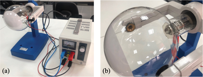
Figure 15.1. (a) The experimental apparatus. (b) Detail of the interior of the diffraction tube—a glass bulb with the electron gun.
Download figure:
Standard image High-resolution imageThe apparatus is schematically shown in figure 15.2. The electrons emitted by the heated cathode are constrained to a narrow beam by an aperture and are then focussed by means of an electron optical system and accelerated by a voltage V. The resulting tight, monochromatic beam then passes through a micro-mesh nickel grating situated at the aperture of the gun. Onto this grid, a thin layer of polycrystalline graphitized carbon has been deposited by vaporization. This layer affects the electrons in the beam much like a diffraction grating.

Figure 15.2. The experimental set-up of Davisson and Germer.
Download figure:
Standard image High-resolution imageThe result of this diffraction is seen in the form of an image comprising two concentric rings that become visible on the fluorescent screen. A spot resulting from the undeflected electron beam continues to be visible at the centre of the rings, as shown in figure 15.3. Each ring corresponds to a Bragg reflection on the atoms of the graphite layer. A magnet is also supplied with the tube. This allows the direction of the electron beam to be changed, which may be necessary if the graphite target has slight damage as a result of the manufacturing process or due to later overheating.

Figure 15.3. Diffraction rings around the non-diffusion electron beam visible on the fluorescent screen.
Download figure:
Standard image High-resolution imageThe anode voltage can be regulated (figure 15.2) in the range of 0–5000 V. Regarding the
geometric characteristics of the experimental set-up, the distance from the graphite
target to the fluorescent screen is (125 ± 2) mm, the fluorescent screen and glass bulb
have diameters of, respectively, 100 and 130 mm, and the total length is 260 mm, while
the lattice constants of graphite are
 and
and
 . More details concerning the apparatus can be
found in the manufacturer's manual [8].
. More details concerning the apparatus can be
found in the manufacturer's manual [8].
The variation of the anode voltage V involves the modification of the radius ri of the diffraction rings, i.e. the reduction of the voltage causes the increase of the radius ri . This observation agrees with de Broglie's postulate, according to which the λ wavelength is differently proportional to the impulse p.
15.4. Measurement of the reticular step of graphite
15.4.1. Theoretical outline
Bragg's law
When x-rays of a fixed wavelength are incident on a crystal surface at certain incident angles, intense reflected x-rays are produced when the wavelengths of the scattered x-rays interfere constructively. In order for the waves to interfere constructively, the differences in the travel path must be equal to integer multiples of the wavelength. When this constructive interference occurs, a diffracted beam of x-rays will leave the crystal at an angle equal to that of the incident beam.
Consider a single crystal [9] with aligned planes of lattice points separated by a distance d, see figure 15.4. Monochromatic x-rays A and A' are incident upon the crystal at an angle θ and the travel path length difference between the ray paths ABC and A'B'C' is an integer multiple of the wavelength. Constructive interference will occur for a combination of the specific wavelength (λ), crystal lattice planar spacing (d) and angle of incidence (θ). Each rational plane of atoms in a crystal will undergo refraction at a single, unique angle (for x-rays of a fixed wavelength). The relationship between the wavelength of the incident x-rays, angle of incidence and spacing between the crystal lattice planes of atoms is known as Bragg's law [10], expressed as

where n (an integer) is the 'order' of reflection,
λ is the wavelength of the incident x-rays, d is
the inter-planar spacing of the crystal and θ is the angle of
incidence. The formula is explained analytically by considering an optical path
difference of
 .
.

Figure 15.4. Bragg's law reflection. The diffracted x-rays exhibit constructive interference when the distance between paths ABC and A'B'C' differs by an integer number of wavelengths (λ).
Download figure:
Standard image High-resolution imageThe principle of Bragg's law is applied in the construction of instruments such as Bragg spectrometers, which are often used to study the structure of crystals and molecules.
Since graphite, which is the target of the electron beam in the experiment
presented, has a hexagonal structure (as illustrated in the diagram of figure 15.5) with two distances
of the lattice planes
 and
and
 , in the first order of diffraction
(n = 1) two diffraction rings with diameters of, respectively,
, in the first order of diffraction
(n = 1) two diffraction rings with diameters of, respectively,
 and
and
 will be observed (see figure 15.6).

Figure 15.5. Hexagonal structure of graphite with distance characteristics d10 and d11 between the lattice planes.
Download figure:
Standard image High-resolution image
Figure 15.6. Diffraction rings with diameters of r10 and r11 observed on the fluorescence screen.
Download figure:
Standard image High-resolution imageMeasurement of the distances of the lattice planes
In order to determine the dependence of the radius r of the diffraction rings as a function of the acceleration voltage of the electron beam, it is necessary to consider the geometry of the diffraction tube, shown in figure 15.7, where
- •θ is the angle of deviation of the electrons.
- •r is the radius of the diffraction rings.
- •L is the distance between the graphite sample and the plane containing the rings.
- •R is the radius of the diffraction tube.
Using the trigonometric relations and the chord theorem, we obtain the following relations between the variables r, L, R and θ:

Since
and combining the two relationships (15.1), we obtain

from
the form of duplication for the tangent function, and replacing
 , the following expression is obtained for
the quantity L:
, the following expression is obtained for
the quantity L:
Applying the duplication formula for the cosine function and simple mathematical steps, the relation that gives the distance L as a function of the variables R and θ is
Using the trigonometry theorems it is possible to express the length L, the distance between the graphite sample and the plane containing the diffraction rings, as a function of the radius of the latter:

Since the diffraction
angles θ are small
( ) the following approximations can be
used,
) the following approximations can be
used,
and if n = 1, Bragg's law takes the following simplified form:

From the first equation of (15.1), the radius of the diffraction rings can be written as

from which we obtain the angle 2θ,

The wavelength can thus be rewritten in terms of the distances r and L:

Define this
wavelength as
 (the Bragg wavelength)
and, since r and L depend on the voltage
V, equation (15.3) is rewritten as
(the Bragg wavelength)
and, since r and L depend on the voltage
V, equation (15.3) is rewritten as

where the dependence of L on r is given by equation (15.2).

Figure 15.7. Schematic representation of Debye–Scherrer diffraction.
Download figure:
Standard image High-resolution image
The de Broglie hypothesis states that all matter exhibits wave-like properties and relates the observed wavelength of matter to its momentum, in the relationship

recall that h is Planck's constant. This wavelength is called the de Broglie wavelength.
In the diffraction tube that reproduces the Davisson–Germer experiment, the
electrons are accelerated by the voltage V and subsequently affect
the target with velocity
![$\mathit{\unicode[Book Antiqua]{x76}}$](https://content.cld.iop.org/books/10__1088_978-0-7503-2678-0/revision2/bk978-0-7503-2678-0ch15ieqn42.gif) . From mechanical energy
conservation,
. From mechanical energy
conservation,

then the speed of the electrons is

from which we obtain the momentum
or

Replacing the momentum p in the de Broglie
relation, we obtain that the wavelength
 is
is

According to the de
Broglie hypothesis, the two wavelengths
 and
and
 must be equal, so they equate equation
(15.4) with
equation (15.5):
must be equal, so they equate equation
(15.4) with
equation (15.5):

Developing the Taylor
series (15.6)
for  , the relation that links the radius of
the diffraction rings r and the voltage V is
obtained:
, the relation that links the radius of
the diffraction rings r and the voltage V is
obtained:

Since
R, the radius of the diffraction tube, is provided by the
constructor ( ) mm), the factor

is a constant, where m and e are, respectively, the mass and the charge of the electron. By replacing the numeric values of all the constants, α is equal to
for the purpose of the experiment it is more convenient to express the unit of measurement of α in units of 'nm cm':
By replacing α in equation (15.7), it is possible to obtain the dependence of the radius of the diffraction rings r on the voltage V:

As anticipated, the radius r is inversely proportional to the acceleration voltage of the electrons, with precision, r decreases as the square root of the acceleration voltage increase.
Through equation (15.8), the distances of the lattice planes can be obtained by measuring the rays of the diffraction rings as a function of applied voltage.
15.4.2. Experimental part
In order to demonstrate de Broglie wave–particle duality and verifies his equation,
in the proposed experiment, which tries to reproduce the original experiment of
Davisson and Germer, the difference of potential V (measured in
kilovolts) is varied and is measured using the radius r (measured in
centimeters) of a single diffraction ring. The data can be collected in a table such
as the example shown in table 15.1. The errors in the voltage V and in the radius
r are produced by the sensitivity of the instruments. In
particular, in the instrumentation used in the experiment the
 sensitivity is equal to 0.1 kV, while the
error on the quantity
sensitivity is equal to 0.1 kV, while the
error on the quantity
 is obtained from the formula of propagation
of errors [11]:
is obtained from the formula of propagation
of errors [11]:
From the experimental data it is possible to estimate the reticular step d through a linear fit. In fact, if in equation (15.8)

arises, a linear relationship between x and y is obtained,

where the quantity

represents the angular coefficient of the line equation (15.9). From the linear interpolation the coefficient m is obtained and from it the reticular step d and the corresponding error are obtained through the relations

By comparing the
experimental value obtained with that reported by the manufacturer, it can be
concluded that the experimental results are in a close agreement with the de Broglie
equation. The starting hypothesis, the equality of the
 and
and
 wavelengths, is verified, therefore the de
Broglie hypothesis is validated.
wavelengths, is verified, therefore the de
Broglie hypothesis is validated.
Table 15.1. A sample of experimental data collected for the Davisson and Germer experiment. The table contains the difference of potential V, its error and the radius r. (∗Numeric values are merely used as an example.)
 |
 |
 |
 |
|---|---|---|---|
| 1.41∗ | 0.01∗ | 4.2∗ |
Acknowledgements
The author would like to thank A Stabile for useful discussions about the Davisson and Germer experiment and its realization.
Appendix
A. Relativistic approximation
The momentum of the electrons present in de Broglie's relation
( ) was obtained [1] by considering the electron as a
non-relativistic particle. It is given by
) was obtained [1] by considering the electron as a
non-relativistic particle. It is given by

and for a non-relativistic particle the relation of the conservation of mechanical energy is

However, around 4 kV,
the electrons in the diffraction tube of the experiment have a speed equal to about
 of the speed of light in a vacuum,
c.
of the speed of light in a vacuum,
c.
To take account of any relativistic corrections [12], the classical relationship of conservation of mechanical energy must be replaced with the relation

where γ is the Lorentz factor

and m is the electron rest mass
Replacing γ in equation (A.1),
Performing simple calculations, it is possible to obtain the velocity of a particle in the relativistic case:

While the relativistic momentum is given by the expression

Replacing
 of equation (A.2), it is possible to obtain
Consequently the
relativistic momentum is greater than the classical one, therefore it follows that the
de Broglie relativistic wavelength
 is smaller than the classical one, that
is,
is smaller than the classical one, that
is,

while the classic expression is

It is
interesting to evaluate the relative error that is committed considering the
relativistic electron instead of the 'slow' one. By developing the relationship (A.3) in series,
with
 , the estimate of this error is provided
by
, the estimate of this error is provided
by

where the voltage V is expressed in kilovolts.
Instead the relative measurement error in the determination of the wavelength (A.4) is provided by the expression [11]
In the case of the
instrumentation used in the experiment described, the
 sensitivity is equal to 0.1 kV,
therefore
sensitivity is equal to 0.1 kV,
therefore

In table A1 the values of the two relative errors, equations (A.5) and (A.6), have been calculated for some values of the applied voltage. It is possible to observe that for voltage values lower than 6.3 kV the relative wavelength measurement error is greater than the relativistic one, and therefore predominant. Therefore the relativistic effects are negligible, while for values higher than 6.3 kV the relativistic error prevails over the measurement error and consequently the approximation of a 'slow' electron is no longer valid.
Table A1. Comparison of relative errors in the classical case and in the relativistic case, at certain voltage values.
| 1 kV | 5 kV | 6.3 kV | 10 kV | |
|---|---|---|---|---|

|

|

|

|

|

|

|

|

|

|
In the case of the instrument used to reproduce the experiment of Davisson and Germer, the maximum voltage that can be reached with the generator supplied is 5 kV, for this reason the electron can be considered 'slow'.
References
- [1]de Broglie L 1925 Recherches sur la théorie des quanta Ann. Phys. 10 22–128
- [2]Greenberger D et al 2009 Compendium of Quantum Physics: Concepts, Experiments, History and Philosophy (Berlin: Springer)
- [3]Taylor E F and French A P 1979 An Introduction to Quantum Physics (Cheltenham: Stanley Thornes)
- [4]Russo A 1981 Fundamental research at Bell Laboratories: the discovery of electron diffraction Hist. Stud. Phys. Sci. 12 117–60
- [5]Krane K 1983 Modern Physics (New York: Wiley)
- [6]Davisson C and Germer L H 1927 Diffraction of electrons by a crystal of nickel Phys. Rev. 30 705–40
- [7]Weinert F 2009 Compendium of Quantum Physics , ed D Greenberger, K Hentschel and F Weinert (Berlin: Springer)
- [8]3B Scientific Electron Diffraction Tube Manual https://www.3bscientific.com/product-manual/1013889_EN.pdf.
- [9]McQuarrie D A 1997 Physical Chemistry: A Molecular Approach (Sausalito, CA: University Science)
- [10]Bragg W L 1934 The Crystalline State vol 1 (New York: Macmillan)
- [11]Taylor J R 1997 An Introduction to Error Analysis: The Study of Uncertainties in Physical Measurements (Sausalito, CA: University Science)
- [12]Stabile A Lecture notes held in the framework of Progetto Lauree Scientifiche, Dipartimento di fisica 'E.R. Caianiello', Università di Salerno, Italia