
The Classification of crystals
Published September 2017
•
Copyright © 2017 Morgan & Claypool Publishers
Pages 3-1 to 3-13
You need an eReader or compatible software to experience the benefits of the ePub3 file format.
Download complete PDF book, the ePub book or the Kindle book

Permissions
Abstract
This chapter discusses the details of crystallography and diffraction studies of crystal structures. We look in detail at how symmetry is used to classify all solids into only seven crystal systems and the fourteen Bravais lattices; and we see how the vast majority of organic crystals are to be found in only three crystal systems. We then look at the details of x-ray and neutron diffraction studies of crystals and powders to determine the architecture of the atoms and molecules in the solid under study. Finally, we look at how one progresses from a measured diffraction pattern to a full determination of the crystal structure.
Form is a diagram of forces
(D'Arcy Wentworth Thompson, 1860–1948)
3.1. The intimacy within solids
Solids are not lifeless permanent structures where the component molecules and atoms are held at certain distances and orientations giving a 3-dimensional structure that can exist for eternity. In ice, for example, at temperature close to its melting point there is sufficient motion that the networks of hydrogen bonds that hold the crystal together, are forming and breaking at 105 per second. Yet this complex dynamic allows ice to have a structure that exists over extended distances (Antarctica), yet in water it only permits a short-range structure, extending over a few molecular diameters.
But because of the manner in which the various sub-units or individual molecules that compose the solid are bound together, they are able to undergo concerted or coordinated motion where all the component molecules move together. These concerted or coherent motions give solids their particular properties, and allows for the possibility of structural instabilities. That is, at a particular temperature, the thermal excitation of the solid (a solid absorbs thermal energy by the excitation of the weak bonds between the constituent molecules) arising from the available thermal energy causes the existing 3-dimensional solid structure to become unstable and the solid may undergo a structural phase transition where the 3-dimensional solid structure changes; it rearranges itself in an instant. In a solid-state phase transition, the material remains a solid and the chemical formula does not change, but all the sub-units in the solid are organized differently so as to maximize the intermolecular forces in the new, more thermally agitated (or less thermally agitated if we are lowering the temperature of the solid) environment.
It is the thermally-driven motion of atoms and molecules that give all the phases of matter their strange and unique properties. There is motion everywhere we look in Nature.
3.2. Crystallography
We now need to consider how to describe and to classify the solids formed from molecules; from the tens of millions of molecules of which we presently aware.
When we examine a crystal, particularly a large well-formed crystal, the quality and geometric perfection of the sides pleases us. The perfection and sharpness of the angles doubles our pleasure. Then we turn the crystal and upon viewing a second side, which is in all respects identical to the first side, the pleasure of observation seems to be squared. Then looking at a third side, a fourth side, our pleasure appears to increase in orders of magnitude. 1
Crystals may only be solid manifestations of ionized atoms or neutral molecules being held together at particular distances and at particular orientations by intermolecular forces of an electromagnetic origin, yet they are as near to an aesthetic perfection as we may come across in Nature.
All crystals contain a great deal of symmetry and order, but this is particularly the case with ionic crystals. And it is via this inherent internal long-range order, which is often reflected in the shape and form of the crystal one can hold in one's hand that a classification of crystals has arisen. Crystals are defined by symmetry operations; for example, does rotation of the crystal about some axis, or reflection through some plane in the crystal result in the same structure being viewed (that is, bringing itself into co-incidence), or does the symmetry operation generate a new structure? Let us take the example of sea-salt or sodium chloride, which crystallizes into cubic forms.
How can we define a cubic crystal? Well, if you rotate a cube (which is a very symmetric object) by 90° about an axis passing through the centres of a pair of opposite faces, you return the cube to its original position; the two positions may be superimposed, because nothing has changed by the operation of rotation. For a cube, such a rotation is said to be a symmetric operation; a C4 operation as there are four such axes of rotation.
Similarly, if we slice a cube in half perpendicular to a C4 axis of rotation, the two half-cubes are mirror images. The plane of the slice is then said to be a mirror plane or a plane of symmetry and is denoted by m. In a cube there are three such planes (one of which will slice through opposing corners of the cube). A cube also has other symmetry axes: six 2-fold axes (C2 or 180° rotators) passing though the midpoints of opposite edges, and four 3-fold axes (C3 or 120° rotators) passing though opposite corners. Besides its symmetry axes, a cube has other symmetry elements. The cube also has the important symmetry property, an inversion centre and centre of symmetry, i; such that any point that outlines the cube when projected through i comes into coincidence with itself.
In this way, we may describe the symmetry of the cube in terms of its symmetry elements or symmetry operations (they are mathematical operations): three C4, four C3, six C2, three m perpendicular to C4, six m perpendicular to C2, and i. More than one symmetry operation can belong to a given symmetry element. So C4 can transform the symmetry operations of rotation by 90°, 180°, 270° and 360°; that is, C4(π/2), C4(π), C4(3π/2) and C4(2π) 2 .
For all crystals, the set of all symmetry operators forms a group; and this group is a mathematical entity which obeys certain rules. These symmetry operations in crystals are entirely analogous with the application of symmetry in the quantum mechanics of sub-atomic particles, with a view to determining which particular forces of Nature act upon which sub-atomic particles. Indeed, symmetry is as powerful a tool and a means of studying problems in physics as it is in art.
The cubic system contains a great deal of symmetry. If there is less symmetry in the system being examined, for example, if the C4 axes are actually found to be only C2 axes, and there are no C2 axes with mirror planes normal to them, then we are looking at a system of lower symmetry (in fact, the point group of iron pyrites defined as Th ) than the full cubic system seen in rock-salt. As any artist will tell you, symmetry is at the heart of looking at and understanding Nature. And even at the molecular scale, symmetry is the key to describing structure and function. Molecules often interact symmetrically, producing crystals which therefore possess something of the symmetry of the molecule. Textbooks often deal with this subject in a manner remote from practical use. This subject, which is essentially about the manipulation of objects in three dimensions, is highly mathematical. Indeed, the physics and mathematics of crystallography was established in the 18th and 19th centuries, well before we had the slightest idea of how atoms and molecules interact and how they are arranged in crystals.
The faces of a crystal (usually, the first means of trying to identify to which symmetry class a crystal belongs) can be described by a set of three non-coplanar axes. If we construct such axes so that their lengths are in definite ratios, a finite set of crystal systems can be identified, even though the total number of crystals is enormous. Consider a non-coplanar axis system (a, b, c) starting at an origin O. These three axes may be cut by a plane ABC, making intercepts at OA, OB, OC. Expressed as fractions of the crystal axes, their lengths are OA/a, OB/b and OC/c; and they have reciprocals a/OA, b/OB and c/OC. Given that ratios of rational numbers can always be reduced to whole numbers by use of appropriate multiplicative factors (the law of rational intercepts), these reciprocal intercepts will always be in the ratio of the whole numbers (hkl) for planes that are crystal faces.
In 1839, the Welsh mineralogist and physicist William Hallowes Miller (1801–1880) introduced such reciprocal intercepts to designate crystal faces; they can also be used to define planes within crystals. If a face is parallel to a given axis, the intercept is at infinity, and the corresponding Miller index will be 1/∞ = 0. Depending upon the axes required for the law of rational intercepts to hold, all the millions of crystals can be divided into only seven crystal systems.
In crystallography, the terms crystal system, crystal family and lattice system each refer to one of several classes of space groups, lattices, point groups or crystals. They are similar but slightly different and are all defined by symmetry operations; consequently, there is often confusion between them: in particular the trigonal crystal system is often confused with the rhombohedral lattice system, and the term crystal system is sometimes used to mean lattice system or crystal family. Informally, two crystals are in the same crystal system if they have similar symmetries; though there are many exceptions to this rule.
Space groups and crystals are divided into seven crystal systems according to their symmetry properties (point groups), and into seven lattice systems according to their Bravais lattices 3 . Five of the crystal systems are essentially the same as five of the lattice systems, but the hexagonal and trigonal crystal systems differ from the hexagonal and rhombohedral lattice systems. The six crystal families are formed by combining the hexagonal and trigonal crystal systems into one hexagonal family, in order to eliminate confusion. The 14 Bravais lattices are grouped into seven lattice systems: triclinic, monoclinic, orthorhombic, tetragonal, rhombohedral, hexagonal and cubic.
In a crystal system, a set of point groups and their corresponding space groups are assigned to a lattice system. Of the 32 point groups that exist in three dimensions, most are assigned to only one lattice system, in which case both the crystal and lattice systems have the same name. However, five point groups are assigned to two lattice systems, rhombohedral and hexagonal, because both exhibit 3-fold rotational symmetry. These point groups are assigned to the trigonal crystal system. In total there are seven crystal systems: triclinic, monoclinic, orthorhombic, tetragonal, trigonal, hexagonal and cubic.
The relation between 3-dimensional crystal families, crystal systems and lattice systems is given in table 3.1.
Table 3.1. Relationship of crystal classifications.
| Crystal family | Crystal system | Required symmetries of point group | Point groups | Space groups | Bravais lattices | Lattice system |
|---|---|---|---|---|---|---|
| Triclinic | Triclinic | None | 2 | 2 | 1 | Triclinic |
| Monoclinic | Monoclinic | 1 2-fold axis of rotation or 1 mirror plane | 3 | 13 | 2 | Monoclinic |
| Orthorhombic | Orthorhombic | 3 2-fold axes of rotation or 1 2-fold axis of rotation and 2 mirror planes. | 3 | 59 | 4 | Orthorhombic |
| Tetragonal | Tetragonal | 1 4-fold axis of rotation | 7 | 68 | 2 | Tetragonal |
| Hexagonal | Trigonal | 1 3-fold axis of rotation | 5 | 7 | 1 | Rhombohedral |
| 18 | ||||||
| Hexagonal | Hexagonal | 1 6-fold axis of rotation | 7 | 27 | 1 | Hexagonal |
| Cubic | Cubic | 4 3-fold axes of rotation | 5 | 36 | 3 | Cubic |
| 6 | 7 | Total | 32 | 230 | 14 | 7 |
The seven crystal systems consist of 32 crystal classes (corresponding to the 32 crystallographic point groups). The names given to the 32 crystal classes were formulated in the 19th century, and are based on the morphology of the crystal of the material in question. Thus, in the monoclinic system there are three crystal classes: monoclinic-sphenoidal (Schönflies symmetry C2), monoclinic-domatic (Schönflies symmetry Cs) and monoclinic-prismatic (Schönflies symmetry C2h); and these names define the shape of a specimen of the material. These names provide no real information about the arrangement of atoms in the crystals as they define the outward appearance of a macroscopic crystal, as the physicists who derived these names knew nothing of molecules and polyatomic assemblages. However, there will be an inference of outward morphology on internal atomic structure.
All crystalline materials must fit into one of the symmetries described in table 3.1, which does not apply to quasicrystals.
Table 3.2. The geometry of crystal systems and Bravais lattices.
| Crystal system | Axes | Angles | Bravais Lattices |
|---|---|---|---|
| Cubic | a = b = c | α = β = γ = 90° |
|
| Tetragonal | a = b; c | α = β = γ = 90° |
|
| Orthorhombic | a; b; c | α = β = γ = 90° |
|
| Rhombohedral | a = b = c | α = β = γ |
|
| Hexagonal | a = b; c | α = β = 90°; γ = 120° |
|
| Monoclinic | a; b; c | α = γ = 90°; β |
|
| Triclinic | a; b; c | α; β; γ |
|
In table 3.2 we see details of the geometry of the Bravais lattices. Note that in the Miller index for a crystal face, it is only the ratio h:k:l that is of importance; thus, (220) would be the same face as (110); the parentheses denote a crystal face 4 . However, for planes within a crystal, multiplication by an integer would change the inter-planar spacing; thus, the planes 200 would include the 100 and the set of planes midway between them. (Miller indices without parentheses denote a set of planes.) If we wish to refer to all equivalent planes of a crystal; that is, a form of a crystal, we use curly brackets; for example, we would say the cubic sodium chloride crystal has the {100} form.
Tables 3.1 and 3.2, display essential characteristics of crystal systems; that there are only C2, C3, C4 and C6 rotational axes to be found in Nature. There are, for example, no 5-fold axes, or 8-fold axes. There are, however, molecules that have a 5-fold symmetry; for example, ferrocene Fe(C5H5)2 (see figure 2.5). But this molecular symmetry is not necessarily transformed into the symmetry of the crystals formed from those molecules. The reason for this incommensurability is that it is not possible to fill Euclidian space with objects of 5-fold symmetry. The absence in crystals of axial symmetry elements other than 2-, 3-, 4- and 6-fold axes tells us that crystals can only be constructed of repeat subunits which fill space in distinct geometric patterns. That is, the crystal forms seen in Nature are outward manifestations of internal regularities and structure.
It is upon a lattice that one may describe in space a regular array of subunits. Such a lattice is a regular, infinite array of points in space, arranged at the intersection points of three ranges of equidistant planes. These points may be joined together so as to construct unit cells, which fill all space. As we have seen, there are restrictions on the forms of unit cells that fill all space. Sometimes we do not use a unit cell in which all the points are at the corners, but instead use a face-centred, end-centred, or body-centred unit cell. Unit cells in which all the points are at the corners form primitive lattices, the others form centred lattices. But there are only 14 possible lattices; they were identified by Auguste Bravais and are termed the Bravais lattices (see tables 3.1 and 3.2).
A lattice is merely a mathematically useful array of points in space. If at each of the points in a lattice we were to place an atom or a molecule, held in place by the balance of the attractive and repulsive intermolecular forces, we would obtain a crystal structure. All crystal structures are based on one or other of the 14 Bravais lattices. Just as a lattice is composed of unit cells that pack together to fill space, a crystal structure is also made of unit cells. So, if we know the location of the atoms, or ions, or molecules within a unit cell we have enough data to determine the crystal structure.
The unit cell provides a convenient way to locate the centres of mass of each atom, ion or molecule within a crystal structure. The lengths of the sides of the unit cell, a, b, c, are taken as unit lengths, and the position of any point in the cell is designated as (u = x/a, v = y/b, w = z/c); for example, in the cubic unit cell, the body-centred position would be (½ ½ ½), a face-centred position (½ 0 ½), and so on. A general position would be, uvw. In terms of the dimensions of the unit cell, we may write for the distance between sets of planes hkl (in the cubic system):

where a0 is the edge of the unit cell. For example, the distance between the 111 planes in rock-salt is d111 = a0 /√3 = 3.25 Å.
Solids and crystals are composed of near-infinite arrays of atoms, or molecules, or ions, yet how and why do they fill space in the manner they do? This is the great question of solid-state science; for example, why is the crystal structure of calcite the way it is, yet the crystal structure of rock-salt is totally different? It is similar, yet very different, with different physical properties.
Space groups are essential to crystallographers and those seeking to investigate how crystals are engineered. Firstly, they allow crystal structures to be described without the need to list every atom and its 3-dimensional coordinates within the unit cell. Secondly, determination of space-group symmetry simplifies the determination of a crystal structure, whether from single-crystal or powder diffraction data. Finally, the coordinates of a crystal structure cannot be refined reliably without a knowledge of the space-group symmetry. However, it is not practical, nor is it necessary to know all of the space groups as the frequency of space groups, as observed in the Cambridge Structural Database, provide the following statistics:
| Crystal System | Frequency in the Database |
|---|---|
| Triclinic | 21% |
| Monoclinic | 53% a |
| Orthorhombic | 21% |
| Tetragonal | 2% |
| Trigonal | 2% |
| Hexagonal | 0.5% |
| Cubic | 0.5% |
aAnd P2(1)/c is by far and away the most common space group in the monoclinic system for packing non-chiral molecules with no symmetry; they will pack best with a screw axis perpendicular to a glide plane (based on the ideas of Alexander Kitaigorodsky) as these symmetry elements avoid the formation of void holes in the crystal structure, so enabling close packing (see http://pd.chem.ucl.ac.uk/pdnn/symm3/sg14a1.htm for technical details). According to the Cambridge Structural Database, this space group accounted for around 1 in 3 of all crystal structures in this system. For chiral molecules one loses the inversion centre and glide plane so space group P2(1) becomes the most common space group.
These statistics demonstrate that molecular crystals usually have low-symmetry crystal structures; over 95% of the structures belong to either the triclinic, monoclinic, or orthorhombic crystal systems. The great variety of molecular shapes are accommodated in only three crystal systems.
The crystal system to which a solid belongs will immediately tell us something about the manner in which the atoms and molecules that compose the crystal are arranged within the solid. However, to see precisely how the individual atoms and molecules are ordered and arranged in the crystal, we need to look into that solid. But how does one explore this internal perfection of the crystal, and determine the orientation and spacing of the atoms and molecules within?
3.3. X-ray diffraction
In 1913, the German physicist Max von Laue (1879–1960) suggested the possibility of using the recently discovered x-rays as a means of probing the structure of crystals; a suggestion for which he won the Nobel Prize for physics of 1914. He reasoned that as the wavelength of x-rays (typically 1–2 Å) is of the same order as the inter-atomic distances inside the crystal, this radiation was ideal for the study of crystal structure. If x-rays were allowed to strike the crystal, the rays would penetrate into the crystal and would be scattered or reflected by the electrons of the atoms or ions that form the crystal. The x-rays reflected from different layers of the atoms would then undergo interference to produce a diffraction pattern. In other words, crystals would act as a 3-dimensional grating for x-rays 5 .
Consider a beam of x-rays, of wavelength λ incident upon the face of a crystal. Let us further suppose that the crystal face is made up of a regular array of atoms located at lattice points. The electric field of the x-ray photons will interact with the electrons in the atoms of the array, and as a result, the x-rays will be scattered from each atom. These scattered rays or photons do not form a coherent beam as they will interfere destructively with each other. First consider the scattering by a single line of equispaced scattering centres of separation a. The condition that waves scattered from two adjacent points be in phase is that their path difference equals an integer number (n) of wavelengths. For a line of equispaced scattering centres, the path difference is:

where t − s is the path difference of two wavelets whose angle of incidence upon the array and scattering from the array are given by θ and φ. When n = 0, we have the zero-order diffracted rays forming a cone generated around the direction of incidence. The direction of this scattering cone depends only upon the direction of incidence of the incoming x-rays and not upon the spacing of the scattering centres. When n becomes finite, the higher order diffracted beams are also cones, but their position now depends on the spacing, a. It was the observation that a randomly ordered set of scattering centres (an amorphous solid) generated diffuse scattering that led to the explanation for the scattering from a 3-dimensional crystal.
Two British physicists, William Lawrence Bragg (1890–1971) and his father William Henry Bragg (1862–1940) determined the first crystal-structure by examining sea-salt; that is, they demonstrated the cubic structure of the NaCl crystal using x-rays. In the Braggs' treatment, the x-rays strike the crystal at a defined angle θ; these rays penetrate the crystal, and are reflected by different parallel layers of ions in the crystal.
A strongly diffracted beam will only be seen if all the rays reflected from the various layers of the crystal are in phase, which is why the wavelengths have to be of the same size as the spacings 6 . The waves or rays reflected by different layers will be in phase if the difference in the path length of the waves reflected from the successive planes is equal to an integral number of wavelengths (see figure 3.1)

Figure 3.1. X-ray reflection and interference from crystals.
Download figure:
Standard image High-resolution imageFigure 3.1 tells us that the beams of x-rays reflected from deeper layers travel further to reach the detector. Three, in-phase x-rays are shown approaching the crystal (rays 1, 2 and 3); one wave is reflected from the first layer of atoms while the second wave is reflected from the second layer of atoms. The wave reflected from the second layer travels a greater distance before emerging from the crystal than the first wave. The extra distance travelled is given by the solid lines between the dashed lines within the crystal. For constructive interference to take place the extra distance travelled by the more penetrating beam must be an integral multiple of the wavelength (λ) of the x-ray radiation. Analysis of this set-up gives us Bragg's Law, or the Bragg condition (W L Bragg) of 1912 for the angular dependence of the scattering; n λ = 2d sin θ, where n is a number and d is the inter-atomic spacing (the distance between two atomic layers of the crystal).
Often it is not possible to obtain a large single, perfect crystal upon which to undertake x-ray scattering experiments, and one must make do with powders of the material. In such powder diffraction studies, instead of a single crystal with a face (hkl) at a well-defined angle θ to the incoming x-ray beam, a mass of finely divided crystals is placed in the beam. In such an experiment, there are so many tiny crystals in the sample that for any particular set of planes (hkl), which meet the Bragg condition, λ = 2dhkl sin θhkl , there is always an appropriately ordered set of crystals. And the direction of the scattered beams is determined only by the angle θhkl . So, for each set of planes (hkl), the scattered radiation forms a cone; and if a flat plate is used as a detector the result will be a series of rings around the incident beam position with the scattering cones (or lines).
To index a powder diffraction pattern, one measures the distance of each line from the central beam spot to obtain the Bragg angle corresponding to each line of the powder pattern. Then from dhkl = (λ/2)/sin θ we may calculate the spacing for each set of reflecting planes (hkl). To index the lines; that is, to assign each one to the proper set of indices hkl, we compare these experimental spacings with theoretical spacings. To do this, we must know the value of a0, but this can be found by fitting two or three experimental dhkl to the appropriate theoretical formula (depending on the crystal class).
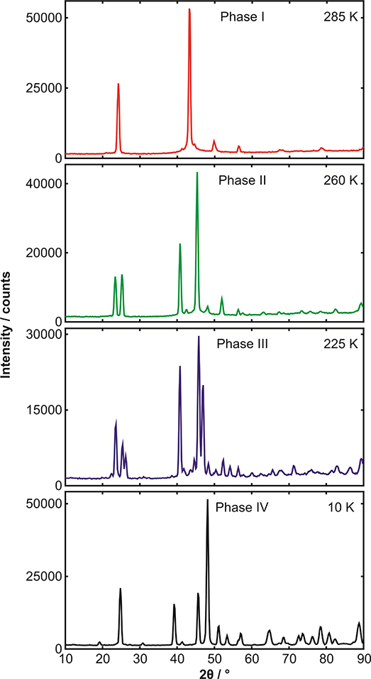
Figure 3.2 displays some typical powder diffraction patterns. Here, the sample is the binary adduct formed by mixing equimolar quantities of benzene and hexafluorobenzene (we will discuss this material later). The sample is not a single crystal of this material, but a multitude of randomly oriented crystallites; that is, a powder. From the data in figure 3.2, this material can be seen to undergo three solid-state phase transitions over the temperature range examined. The problem that must be solved is how to go from a measured set of data, as in figure 3.2, to the crystal structure of this material; that is, how does one determine the architecture of the solid, or how each of the molecules of benzene and hexafluorobenzene are arranged and oriented in the solid?
Figure 3.2. Some high-quality neutron diffraction data. These four diffraction patterns are of the same material, the binary adduct benzene:hexafluorobenzene, but measured at four different temperatures; see image for details. The meaurements were made on the neutron diffractometer, D1B, at the Institut Laue-Langevin, Grenoble, using neutrons of wavelength 2.52 Å. The enormous differences between these diffraction patterns arises because of the structural phase transitions seen in this material at 205 K, 247.5 K and 275 K. What is also clearly seen in the highest temperature measurement is the broad thermal diffuse scattering (from large amplitude motion of the scatterers) underlying the Bragg lines at the highest temperature. In phase IV, the small peak at 19° is the (001) reflection, the large peak at 24.5° is the (110) reflection, the peak at 39.5° is the (002) reflection and the biggest line at 49o is the (−202) reflection.
Download figure:
Standard image High-resolution image
This is a classic problem of indirect methods in experimental science. The diffraction experiment does not measure a single quantity, which may be equated with a single unknown in a theory. In diffraction measurements, one has measured a vast amount of data, which is in some way related to the 3-dimensional coordinates of two polyatomic molecules; to the geometric organization of 24 atoms per molecular pair.
Of course, the experimenter knows that the solid is composed of two molecules, and that these two molecules retain their identity in the organic solid, and the structure of the benzene and hexafluorobenzene are well-known; consequently, one begins to search for the presence of these known molecules—the two molecules both contain a hexagon of carbon atoms. This is done rather laboriously by calculating what the diffraction pattern would be for a series of known orientations of the two molecules under consideration, and then making a comparison with the observed data. This calculation using Bragg's law is rendered trivial by the use of computers, but there is no subtle inference at work here, merely a process of calculation and comparison.
Eventually, one will arrive at a situation where the theoretical model of what you think the structure of the solid is generates a diffraction pattern that resembles in some way the measured data. Then you ask the software to fit (usually with a least-squares algorithm) the model to the data, having fixed several of the variables. In this way, one attempts to refine the model structure; for example, by varying the separation of the two hexagonal rings, or the various angles that define the orientation of the two molecules. This process of structure determination will eventually generate a model that fits the data. Then the structure may be said to have been solved. After having fitted the data, you will have a set of coordinates for each of the atoms in the unit cell of the solid, which via the rules of crystallography gives the structure of the entire solid.
Throughout the remainder of this volume, you will see many dozens of structures of solids, each of which has been generated by sophisticated plotting software (for example, Crystalmaker, http://www.crystalmaker.com/, or the free software Mercury, https://www.ccdc.cam.ac.uk/Community/csd-community/freemercury/) from a set of coordinates deposited in the Cambridge Structural Database (https://www.ccdc.cam.ac.uk/) in the form of a crystallographic CIF file.
It is by examining the scattering of x-rays or neutrons by crystals, and the application of the simple law due to W L Bragg that all the internal dimensions of crystals may be determined. The first crystal structure to be determined was that of sea-salt. But it was less than 40 years later, that Francis Crick and James Watson unravelled the structure of the DNA molecule by using the same technology and experimental procedure; a discovery published in April 1953 (the Nobel Prize was awarded in 1962). When one looks at the serried ranks of atoms and molecules inside the ordered world of a crystal, all marching to infinity or rather to the sharp flat face of the crystal, and when one further imagines these columns and rows of molecules all moving...breathing coherently in response to the ever-present background thermal radiation, one is reminded of Goethe's definition of architecture, crystallized music.
Further reading
There are many useful articles on crystallography to be found in web-based resources such as Wikipedia, but a good source of technical detail, particularly related to x-ray diffraction studies of powders, is Advanced Certificate in Powder Diffraction by Dr Jeremy K Cockcroft, School of Crystallography, Birkbeck College, University of London at http://pd.chem.ucl.ac.uk/pdnn/chapter.htm
Mention must also be made of a publication brought out to celebrate the 50th anniversary of the Braggs' Nobel Prize; 50 Years of x-ray Diffraction by P P Ewald (https://www.iucr.org/publ/50yearsofxraydiffraction). Ewald was one of the pioneers of x-ray diffraction and this work is a hugely informative history of the subject—and is freely available.
Footnotes
- 1
This is almost an intuitive derivation of Ludwig Boltzmann's expression for the entropy of a system, S, i.e. S = kB logW, where W is a measure of the number of states there are in that system. Quotation taken from The Rationale of Verse 1843.
- 2
These symmetry elements, or operations of a cube may be seen at https://sites.google.com/site/greatmathmoments/group.
- 3
Named after the French crystallographer, geographer and physicist Auguste Bravais (1811–1863), who was one of the first to apply physics to understanding the form of the landscape.
- 4
With hkl values, there are five different notations. The diffraction plane indices hkl have no brackets. Indices of a crystal face are given the symbol (hkl) and for all symmetry equivalent faces (e.g. as for cubic symmetry) are given the symbol {hkl} (both are real space usage). So {100} for cubic symmetry comprises (100), (010), (001), (−100), (0–10), and (00–1). To indicate a lattice direction, the notation changes to [uvw] (where d*=ua*+vb*+wc*) where uvw are integer values hkl for Bragg diffraction; for all symmetry equivalent directions this becomes <uvw> (both are reciprocal space usage).
- a
And P2(1)/c is by far and away the most common space group in the monoclinic system for packing non-chiral molecules with no symmetry; they will pack best with a screw axis perpendicular to a glide plane (based on the ideas of Alexander Kitaigorodsky) as these symmetry elements avoid the formation of void holes in the crystal structure, so enabling close packing (see http://pd.chem.ucl.ac.uk/pdnn/symm3/sg14a1.htm for technical details). According to the Cambridge Structural Database, this space group accounted for around 1 in 3 of all crystal structures in this system. For chiral molecules one loses the inversion centre and glide plane so space group P2(1) becomes the most common space group.
- 5
This scattering process is entirely different from the reflection of visible light from a polished surface, a property which is due to the change in velocity of light at the interface.
- 6
Because of the very different length scales of visible light and inter-atomic distances within a crystal, trying to use visible light to study the internal structure of crystals would be like trying to use a bulldozer to sort golf balls; the diffraction and interference of the visible light would be difficult to observe due to the incommensurate length scales between the inside of the crystal and the incoming probing radiation.