Portable magnetic probe for detecting magnetic nanoparticles inside the body
Published August 2018
•
Copyright © IOP Publishing Ltd 2018
Pages 1-1 to 1-19
You need an eReader or compatible software to experience the benefits of the ePub3 file format.
Download complete PDF book, the ePub book or the Kindle book

Permissions
Abstract
This chapter introduces a diagnosis of cancer metastasis using magnetic nanoparticle and newly developed portable magnetic probe. Conventional diagnosis has been performed using radioisotope tracers. The magnetic nanoparticle enables us to perform the diagnosis in small hospitals without dedicated radioisotope facilities. The magnetic probe can be used during surgery. Clinical studies have shown the effectiveness of the magnetic technique, especially for breast cancer.
1.1. Sentinel lymph node biopsy
As breast cancer is the most common cancer among women in many countries, it is important to develop effective diagnostic and therapeutic methods. To select the appropriate therapeutic method for each breast cancer patient, the cancer stage must be correctly identified and the presence and extent of metastasis must be determined.
Metastasis refers to cancerous cells spreading to other organs through the lymphatic and vascular systems, where it subsequently develops. Breast cancer is known to metastasize through the lymphatic system. The lymphatic flow of the breast accumulates in the areola and lymph vessels extending from the areola to the axilla. Lymph nodes are present in the axilla. Thus, because of this structure, in many cases the cancer first metastasizes to the axillary lymph nodes, and subsequently to other organs.
Lymph nodes must be biopsied in order to determine the presence of metastasis. Hence, the lymph nodes are resected, and a prepared section of the biopsy sample is microscopically examined by a pathologist. Staining of the section with hematoxylin and eosin (HE) allows for the assessment of the cellular morphology, which in turn enables the pathologist to differentiate between healthy and cancerous cells. Alternatively, compared to HE staining, immunostaining of the section allows the cancer cells to be identified with higher precision. The properties and malignancy of cancer can also be identified.
The diagnosis of metastasis itself is an invasive process with side effects. If all the axillary lymph nodes are resected, lymphatic flow in the upper arm would be prevented, causing severe lymphedema, among other problems. Such side effects would significantly lower the patient's quality of life.
To minimize such side effects, the concept of sentinel lymph node biopsy (SLNB) is presently being introduced [1, 2]. Sentinel lymph node (SLN) refers to the lymph node that the cancer cells reach first when metastasizing via the lymphatic flow. Cancer first metastasizes to an SLN, then subsequently metastasizes to other lymph nodes and organs. If there is metastasis to an SLN, the possibility of subsequent metastasis to other organs must be assumed. However, if there is no metastasis to an SLN, one can assume that there is no metastasis to other lymph nodes or organs. In such a case, there is no need to resect the surrounding lymph nodes for examination, and these lymph nodes can be conserved. As a result of the advancement in breast cancer examination methods, breast cancer can presently be diagnosed at earlier stages. In developed countries, many cases are negative for SLN metastasis. Thus, SLNB enables the conservation of lymph nodes in many cases, and minimizes the side effects. Figure 1.1 shows the flow of SLNB.
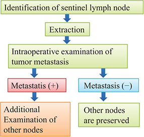
Figure 1.1. Flow of sentinel lymph node biopsy (SLNB).
Download figure:
Standard image High-resolution imageThe most important technique is to identify the SLN. To do so, a tracer is administered near a cancerous lesion. The tracer follows the lymphatic flow to reach a lymph node via the same pathway as the cancer cells. Therefore, if the lymph node that the tracer reaches first can be identified, this is designated the SLN. Regardless of the metastasis pattern, the tracer accumulates in the SLN. In surgical resection for breast cancer, the SLN is first identified with the patient under general anesthesia. The identified SLN is extracted, and cancer metastasis is promptly identified. To that end, a frozen section of lymph node is prepared and HE stained for pathological diagnosis. Using this method, metastasis can be identified within 30 min of lymph node removal. If the result is negative, only the primary lesion in the breast must be removed and lymph nodes apart from the SLN can be conserved. If the result is positive, the axillary lymph nodes are also resected in addition to removal of the primary lesion.
Presently, there are two standard tracers used to identify an SLN: radioisotope (RI) and dye [3–6]. RI is a radioactive drug that consists of tin colloid or technetium phytate. Radiation from a tracer is detected with a gamma ray detector. A tracer, subcutaneously injected into the areola, accumulates in the SLN over several hours or more. Therefore, a tracer is administered the day before surgery. An RI tracer can be detected from a several centimeter distance or more; thus, by passing a gamma ray detector over the skin, the SLN can be identified. This is an advantage of RI. By incising only the skin over the identified SLN, scarring on the skin can be minimized. In addition, because detection is made by a quantitative device output, judgment is objective. A gamma ray detector is used on the resected lymph node to record the count, which determines the amount of tracer that has accumulated in the lymph node.
There are two types of dye: blue dye, such as indigo carmine, and fluorescent indocyanine green (ICG). Accumulation of blue dye in a lymph node is identified with the naked eye, whereas the accumulation of ICG is identified using a dedicated infrared video camera. Because the molecular size of the dye is small, it can flow quickly through a lymph duct and accumulate in a lymph node soon after administration. Therefore, it is usually administered at the beginning of surgery after placing the patient under general anesthesia. Blue dye must be visually confirmed on the surface of the surgical field; however, with ICG, the video camera can visualize accumulation to a depth of several centimeters.
Depending on the individual SLN, both the RI and dye or either one alone will accumulate. By administering both RI and a dye, an SLN can be identified with greater certainty than by administering either one of the tracers. As using both tracers increases the rate of identification, guidelines in many countries, including Japan, recommend the use of both.
1.2. Use of magnetic nanoparticles for sentinel lymph node biopsy
As discussed above, the RI method uses a device for detection; thus, objective identification is possible. This method also has the advantage that an SLN can be detected even when lymph nodes are not exposed on the surface of the surgical field. However, a dedicated facility is necessary to use RI. Presently, many medical facilities do not have a dedicated RI facility; however, surgical treatment of breast cancer is provided in such facilities using only the dye method [7]. The identification rate decreases when only the dye method is used. If ICG is used as a dye, lymph nodes at depths of up to several centimeters can be identified. Because the dye tends to diffuse in the surgical field due to its high fluidity, identification can be difficult in some cases. In facilities where only the dye method is used, a change to use a detection device and a tracer with characteristics similar to those of RI is desirable.
As a technology that can meet such a need, magnetic nanoparticles (MNPs) have been used as a tracer in recent years [8–13]. As shown in figure 1.2, MNPs are injected near the lesion in the breast, and the MNPs that have accumulated in an axillary SLN are detected using a magnetic sensor. An example of MNPs, superparamagnetic iron oxide (SPIO) has been used as a contrast agent in magnetic resonance imaging (MRI) [14, 15]. Their safety for administration to humans has been established. Particles with a diameter of about 10 nm, in which a γ iron oxide core with diameter of several nm is coated with carboxydextran, form an aggregate with a mean particle diameter of 59 nm, which is called ferucarbotran. These particles are dispersed in aqueous solution. This is sold under the product name Resovist, containing 44.6 mg of iron in a 1.6 mL injectable solution. Another product, Sienna+, is a 2 mL injectable solution with similar particles in a different solvent. Sienna+ is manufactured for use in identifying SLNs [8].
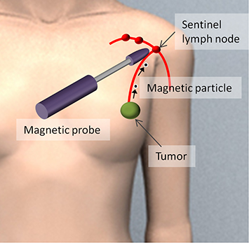
Figure 1.2. SLNB using magnetic nanoparticles (MNPs) [26].
Download figure:
Standard image High-resolution imageMagnetic tracers can be used in medical facilities without the need for special RI facilities. Magnetic particles that are not exposed on the surgical field surface can be detected using a device, and the intensity of the signal can be quantified, thereby assuring objectivity. There is no problem with detection owing to rapid tracer diffusion. These MNPs are classified as a medical device in Europe, whereas they are classified as pharmaceuticals in Japan.
1.3. Pharmacokinetics of magnetic nanoparticles in the lymphatic system
With breast cancer, cancerous cells metastasize via the lymphatic system. When a tracer is injected into a cancerous tumor, it follows the same path as the cancerous cells and accumulates in the lymph nodes. However, when administering tracers to the tumor during surgery, it is necessary to accurately ascertain the location of the tumor and guide the tip of the tracer needle to it in three dimensions. In breast tissue, lymph vessels are concentrated around the areola and extend from there toward the axilla. As such, even if a tracer is administered subcutaneously to the areola, it travels to the axilla, making it possible to identify axillary SLNs. At present, breast cancer metastasis is usually diagnosed by administering a tracer to the areola, rather than the tumor.
The physician must determine the amount of time from administering the tracer to detecting its accumulation in the axillary lymph nodes when performing SLNBs in clinical practice. As such, the pharmacokinetics of the tracer need to be evaluated. The particles of dye, which are small and highly mobile, reach the lymph nodes within a few minutes of administration. However, RI tracers do not flow easily and take more than a few hours to reach the lymph nodes after administration. Accordingly, many medical institutions administer RI tracers the day before surgery. There are also individual differences in the dynamics of tracers, and accumulation tends to require more time in elderly patients.
Tracers do not have the ability to specifically recognize cancerous cells, and they are carried to the lymph nodes by the flow of the lymph. When cancer metastasizes to the lymph nodes, it may affect flow in the nodes. A tracer must be able to accumulate in the lymph nodes whether or not cancer has metastasized there. Furthermore, it is preferable for the tracer to be excreted from the body after an SLNB has been performed.
Figure 1.3 shows human lymph nodes in which a dye tracer and MNPs have accumulated. Lymph nodes are usually about 5 mm in size, but can grow to about 20 mm due to cancerous metastases. Figure 1.3(a) shows both a dye tracer (blue) and MNPs (dark brown). Figure 1.3(b) shows a lymph node slice for use in pathological diagnosis. Areas where MNPs accumulated appear blue because the tracer was stained using Prussian blue. There is a great deal of accumulation around the edges of the lymph node because the lymph flows there.
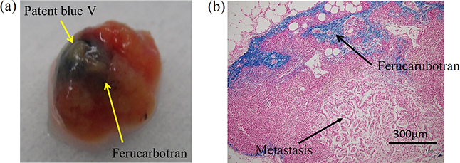
Figure 1.3. (a) Human sentinel lymph node (SLN) with accumulations of blue dye and MNPs (ferucarbotran). (b) Section of SLN with ferucarbotran stained with Prussian blue [16].
Download figure:
Standard image High-resolution imageA vibrating sample magnetometer can be used to quantify the MNPs accumulated in the lymph node. With this device, samples, such as lymph nodes, are placed in a homogeneous magnetic field and magnetized. The magnitude of the magnetic moment produced by the magnetization is proportional to the amount of iron accumulated in the lymph nodes. The lymph node sample is made to vibrate at a set frequency. If a detection coil is placed near the sample, the sample's magnetic moment causes the magnetic flux to the coil to change over time, which generates AC voltage in the detection coil. The amount of accumulated iron can be calculated using the voltage. A gradiometer-type instrument is used in the detection coil, and a superconducting quantum interference device (SQUID) may also be used for higher sensitivity. Figure 1.4 shows the results of measurements taken for human lymph nodes using a vibrating sample magnetometer. The horizontal axis shows the external magnetic field applied to the sample, and the vertical axis shows the magnetic moment generated in the sample. Due to the properties of the MNPs, the magnetic moment increases linearly when the applied magnetic field is small, but when that field exceeds 50 mT, the increase in the magnetic moment reaches a limit at saturation. The figure shows the measurement results from a reference sample with 140 μg of iron and a lymph node cut in half. The error bars are the standard deviation of the measurements from six lymph nodes. These results suggest that approximately 140 μg of iron accumulates in an entire lymph node.
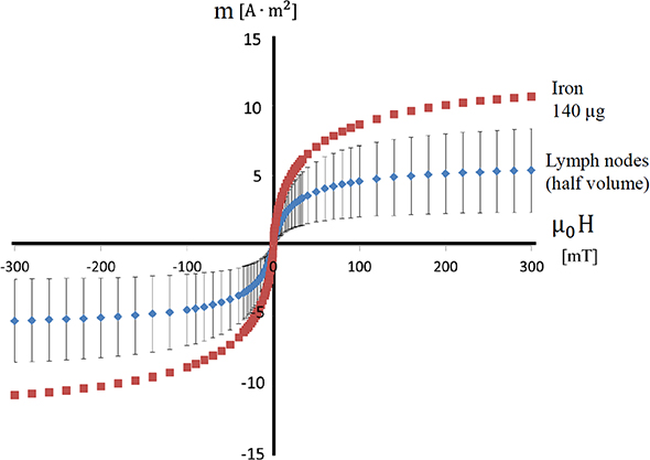
Figure 1.4. Quantification of iron accumulating in SLNs using a vibrating sample magnetometer [16].
Download figure:
Standard image High-resolution imageIn recent years, scientists have been developing methods to apply an alternating magnetic field to samples instead of vibrating them; devices can be made smaller by eliminating moving parts [18]. As shown in figure 1.4, the subsequent changes in the magnetic moment deviate from the sine wave when an alternating magnetic field, which changes sinusoidally, is applied; this is because the magnetic moment of the MNPs has the property of saturation. It is possible to extract the signals originating from the MNPs if the harmonics are retrieved through signal processing. Biological tissue is diamagnetic, and it does not produce harmonics because its magnetic moment is proportional to the strength of the external magnetic field. As such, it is advantageous to use alternating magnetic field methods because they are not affected by the diamagnetism of biological tissue.
Animal study is useful for systematically clarifying the pharmacokinetics of MNPs. This is especially true because it allows researchers to optimize the time from administration to detection, and study whether the most appropriate administration site is within the tumor or subcutaneously in the surrounding area. For instance, researchers have published papers in which MNPs were injected into the legs of mice, and the accumulation in popliteal lymph nodes and inguinal lymph nodes was evaluated [19]. As shown in figure 1.5(a), cancerous cells (B16–BL6) were injected into the right leg, and skin cancer developed over a one-week period. A 5 μL solution of MNPs (Sienna+) and a dye (Patent Blue) were injected intratumorally into the right leg and subcutaneously into the left leg. Following this, an MRI and lymph node excision were performed immediately after administration, and 1, 4, and 24 h later. In MRIs, T1- and T2-weighted images were taken using a device with a 7 T main field. As shown in figure 1.5(b), artifacts caused by local distortions of the magnetic field appeared in lymph nodes where Sienna+ accumulated; the size of these artifacts was evaluated. Additionally, the amount of accumulated iron in the excised lymph nodes was measured with a vibrating sample magnetometer, and slices were created for iron staining. Artifacts in the lymph nodes increased more quickly with subcutaneous administration than with intratumoral administration, according to the results gleaned from MRI observation over time. Additionally, as shown in figure 1.6, the results from measuring the lymph nodes demonstrated that the amount of accumulated iron increased as time passed following administration. These results reveal that, although accumulation to the lymph nodes occurs for either administration site, intratumoral administration requires physicians to wait for a longer time before conducting detection.
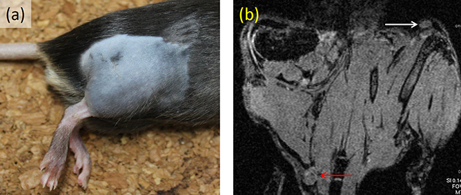
Figure 1.5. (a) Rat model at seven days after introducing cancer cells to right lower limb. (b) Pre-injection T1-weighted magnetic resonance imaging (MRI) with white and red arrows indicating a left inguinal and right popliteal node respectively [19].
Download figure:
Standard image High-resolution image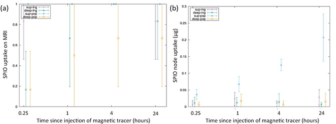
Figure 1.6. (a) Nodal uptake of MNPs recorded on MRI. (b) Nodal uptake recorded using a vibrating sample magnetometer [19].
Download figure:
Standard image High-resolution imageThe pharmacokinetics of MNPs are also affected by particle size. A study has been published comparing the pharmacokinetics of particles of different sizes (diameters of 32 nm, 59 nm, and 111 nm) [17]. MNPs were injected into the areolas of pigs, and accumulation in the inguinal lymph nodes was evaluated. The accumulation was measured using two devices: a handheld magnetometer and a vibrating sample magnetometer. The results showed that the 59 nm MNPs accumulated in the lymph nodes were the quickest and in the largest amounts. This means, of the three particle sizes studied, 59 nm particles are the most appropriate for SLNBs. The previously mentioned Resovist and Sienna+ particles both have a diameter of 59 nm.
1.4. Techniques for detecting magnetic nanoparticles
Resovist, a commercialized MNP, was developed as an MRI contrast agent. Resovist produces a negative contrast and creates signal reduction when it accumulates. MNPs concentrated in lymph nodes also exhibit a contrast effect and, as shown in figure 1.5(b), generate artifacts that make lymph nodes appear as dark voids on images. By comparing lymph node images before and after contrast, one can identify the lymph nodes where MNPs have concentrated [20]. As described, the technique of using MNPs and MRI to make lymph ducts and nodes visible is called magnetic resonance (MR) lymphography. As discussed previously, when approximately 1 mL of a MNP solution is administered, the MNPs accumulate in the SLNs whether or not cancer has metastasized to the lymph nodes. However, it has been reported that when a small amount of MNPs is diluted and administered, they only accumulate if there is no metastasis to the lymph nodes and do not accumulate if there is metastasis [21]. This is because when metastatic cancer develops inside a lymph node, the flow of lymph is hindered. Using this technique makes it possible to diagnose metastasis.
An MRI obtains signals from the hydrogen nuclei contained in biological tissue; the MNPs themselves do not create MRI signals. Meanwhile, a technology currently being developed, magnetic particle imaging (MPI), obtains signals from the MNPs themselves and makes their distribution visible [22, 23]. The magnetic properties of the MNPs are used to take measurements in MPI. The magnetic susceptibility of a tissue containing MNPs is defined as the rate by which magnetization rises when the external magnetic field is increased. As demonstrated in figure 1.4, because there is nonlinearity in the magnetization of MNPs, the magnetic susceptibility depends on the strength of the external magnetic field. The weaker the external magnetic field, the larger the magnetic susceptibility. Coils are positioned around the body, and a distribution of a static magnetic field is generated inside the body. At this time, the electric current to the coils is adjusted so that a point is created within the body where the magnetic flux density is zero. When MNPs are distributed within the body, the magnetic susceptibility of the tissue rises locally at the point at which the magnetic flux density of the static magnetic field is zero. If an alternating magnetic field is applied externally and the alternating magnetic field generated by the MNPs is detected, the magnitude of magnetization can be measured. This magnetization is the local value at the point at which the magnetic flux density of the static magnetic field is zero. If the system changes the electrical current flowing to the coils and moves the point at which the magnetic flux density is zero, it is possible to obtain the magnitude of magnetization at each point. Using such principles, the distribution of MNPs within the body can be visualized. The potential applications of MPI for identifying SLNs are being investigated by some research groups.
MRI and MPI require large equipment, making them difficult to use in operating rooms during surgery. Because the patient's posture during surgery is different from that during MRI and MPI imaging, the position of the lymph nodes also changes. Therefore, MRI or MPI alone are not enough; a small, easy-to-use device is needed to identify SLNs in the operating room. Therefore, researchers have been studying techniques for detecting MNPs with small magnetic sensors. Unlike equipment that uses radiation, a handheld magnetic probe can be introduced in regular operating rooms. Because the number of MNPs that accumulate in the lymph nodes is small, the magnetic sensor needs to be highly sensitive.
A SQUID is a magnetic sensor that offers extremely high sensitivity. Research on identifying SLNs with SQUIDs has been conducted at various research institutions [24]. MNPs are magnetized by geomagnetism, and the magnetic field generated by that magnetization can be detected using SQUIDs. Although SQUIDs have the major advantage of being highly sensitive, they require a coolant such as liquid helium or liquid nitrogen to achieve superconductivity. Additionally, they are strongly influenced by surrounding equipment due to their hypersensitivity, and it is difficult to distinguish between the magnetic field generated by the MNPs and the magnetic field generated by the surrounding equipment. Moreover, because the sensor must be placed inside an insulated container that stores the coolant, there are limits to miniaturization. For these reasons, SQUIDs have not become widespread in clinical practice.
In recent years, there has been rapid development of equipment using magnetic sensors that can be operated at room temperature. Magnetic sensors that operate at room temperature do not require coolant, making it possible for the sensor unit to be miniaturized to a handheld size. Because magnetic sensors that operate at room temperature do not have the high sensitivity of a SQUID, it is necessary to magnetize the MNPs and generate a strong, detectable magnetic field. In many cases, handheld sensor units are equipped with a magnetic field source inside. There are two methods used as magnetic field sources: using coils to generate an alternating magnetic field and using a permanent magnet to generate a static magnetic field. The advantage of coils is that they extract only the signal of the operating frequency, preventing them from being affected by static magnetic fields, such as geomagnetism. However, they also present some issues, such as the time required to stabilize after startup because of heat generation and the larger drive circuits needed due to energy consumption. One product that uses an alternating magnetic field in a handheld sensor is Sentimag, which has been approved in Europe and the United States.
1.5. Portable magnetic probe using a permanent magnet
To identify SLNs using a handheld magnetic probe, the physician searches for lymph nodes while scanning the surgical field with the magnetic probe. Making magnetic probes smaller considerably improves their operability. Additionally, using a permanent magnet as the source of the magnetic field makes it possible to efficiently produce a strong magnetic field without any accompanying electric power consumption or heat generation. Accordingly, magnetic probes using permanent magnets are a good fit for miniaturization, making them useful within the surgical field for searching lymph nodes. Because permanent magnets do not produce heat, they are able to reduce the effects of temperature changes on the sensor. Additionally, because no electric power is needed to generate a magnetic field, drive circuits are smaller and portability is better.
When a magnetic probe is made of a handheld sensor and a desktop drive circuit, the magnetic probe is used within a sterilized environment and the drive circuit is placed outside the environment. This makes magnetic probes difficult to operate. When electric power consumption is kept low by using a permanent magnet, it becomes possible to enclose the entire battery and drive circuit within the handgrip. If such a design is adopted, the magnetic probe can be operated entirely within the sterilized area during surgery, vastly improving its operability.
By making full use of these characteristics, we fabricated a prototype magnetic probe that uses a permanent magnet and small magnetic sensor that can be operated at room temperature. This probe was then used in clinical research [16, 25–28].
Figure 1.7(a) shows the structure of the head of the magnetic probe. The small magnetic sensor, which identifies magnetic fields generated by MNPs, is placed on the tip of the shaft. The magnetic field generated by the permanent magnet installed under the magnetic sensor magnetizes MNPs. Using nonmagnetic brass for the shaft prevents any influence on the measurements. The sensitive direction of the magnetic sensors and the magnetization direction of the permanent magnet are the same as the axial direction of the nonmagnetic shaft. Figure 1.7(b) shows the principles governing the way a magnetic probe detects MNPs. When an SLN where MNPs have accumulated comes close to the head, the MNPs are magnetized by the magnetic field generated by the permanent magnet. The magnetization of the MNPs generates a magnetic field in the surrounding area. As a result, the magnetic flux density applied to the magnetic sensor changes. Detecting this change makes it possible to identify the accumulation of MNPs. As shown in figure 1.7(a), there is a point on the central axis of the permanent magnet where the magnetic flux density becomes zero. The magnetic sensor is placed at this point. When there are no MNPs, the output of the magnetic sensor is zero; in other words, sensor offset can be eliminated. These strategies allow the sensor output signals to be amplified at a high gain, and enable minute changes in magnetic flux density to be detected. Hall effect sensors are suitable as small magnetic sensors. In the area around the point where the magnetic flux density becomes zero, the gradient of the magnetic field is extremely strong. Aside from Hall effect sensors, several types of high-sensitivity magnetic sensors using ferromagnetic materials have been put into practical use; however, these are difficult to operate under a strong magnetic gradient.
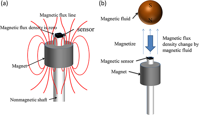
Figure 1.7. (a) Structure of a magnetic probe head equipped with a permanent magnet and Hall effect sensor. (b) Principle of a magnetic probe.
Download figure:
Standard image High-resolution imageTo identify lymph nodes from above the skin, it is preferable to design a large permanent magnet and generate a magnetic field to an increased distance from the magnet. However, the larger the magnet becomes, the larger the tip of the probe must be, leading to poorer operability. This trade-off between magnet size and operability is a challenge, and there is a demand for a magnet designed in a way that optimizes this.
Numerical analysis of the electromagnetic field using the finite element method was performed to evaluate the magnetic flux density applied to the sensor by the MNPs and the effect of magnet size on sensitivity. The point at which the magnetic flux density generated by the permanent magnet becomes zero was used as the reference point. A numerical model of lymph nodes that include MNPs was placed in the area around the sensor, and the value of magnetic flux density generated at the reference point was evaluated as sensitivity ΔB. The larger the value of ΔB, the higher the sensor output that can be obtained. When ΔB is larger than the variation in sensor output caused by noise or other interference, detection of MNPs is possible.
The coercive force of the permanent magnet was set to 976 kA m−1, the inner radius to 2.5 mm, the outer radius to 6.25 mm, and the length to 12 mm. Figures 1.8(a) and (b) show the Bz component of the magnetic flux density generated by the permanent magnet when MNPs are not present. The range where the magnetic flux density exceeds 50 mT was up to 10.4 mm away from the reference point on the central axis. The gradient of the magnetic flux density in close proximity to the reference point was approximately 150 mT mm−1.
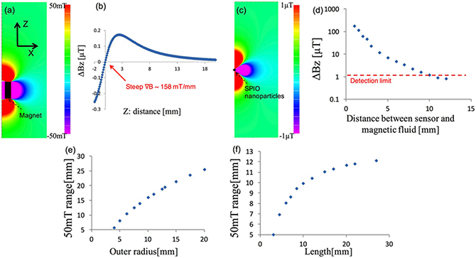
Figure 1.8. (a) Distribution of the longitudinal magnetic field Bz of the permanent magnet. (b) Bz of the magnet on the z-axis. (c) Distribution of Bz of 140 μg of fully magnetized MNPs (5 μL of Resovist) located at z = 10.4 mm. (d) Magnetic field strength ΔB at the sensor position as a function of the distance to the MNPs. Relationships between (e) the outer radius and (f) the length of the magnet, and the distance of the point where the Bz of the magnet is 50 mT [16].
Download figure:
Standard image High-resolution imageAdditionally, to investigate the distribution of the magnetic field arising from the MNPs, when magnetization was saturated, the permanent magnet was removed; a numerical analysis of the magnetic field distribution was then conducted only for the magnetized MNPs. The MNPs were placed at a point 5 mm away from the reference point. Figure 1.8(c) shows the Bz composition of the magnetic field generated by the MNPs when a 2 × 10³ A m−1 magnetization (equivalent to saturation) was applied. A magnetic flux density on the order of 1 μT reaches the area of the reference point.
These data were used to derive ΔB depending on the position of 5 μL of the MNPs. In figure 1.8(d) the horizontal axis shows the distance from the reference point to the MNPs, while the vertical axis shows ΔB at the reference point. The shorter the distance to the MNP, the larger the change in magnetic flux density. When the practical sensitivity limit of the Hall sensor is 1 μT, 5 μL of MNPs can be detected up to approximately 10 mm.
The effect of magnet size on sensitivity was evaluated thereafter. Given a distance between the MNPs and the sensor, the magnetic field, received by the sensor, was at its maximum when the MNPs were saturated. For this reason, we focused on the magnetic flux density at which the MNPs are saturated. Because MNPs are saturated at approximately 50 mT, according to the magnetic characteristics of Resovist shown in figure 1.4, we obtained the distance from the reference point to the 50 mT point. First, the inner radius and the length of the magnet were fixed at 2.5 mm and 12 mm, respectively, and only the outer radius was changed. Figure 1.8(e) shows the location on the central axis where magnetic flux density reaches 50 mT. The horizontal axis shows the outer radius of the permanent magnet. The larger the outer radius, the farther the magnetic field reaches, and the larger the range of saturation of the magnetization of MNPs becomes.
Figure 1.8(f) shows the results when the length of the magnet was changed. The inner radius and outer radius were fixed at 2.5 mm and 6.25 mm, respectively. Similar to the results obtained for the outer radius, the longer the magnet, the larger the range within which magnetic flux density exceeded 50 mT became. The effect of changing the length was smaller than the effect of changing the outer radius. The results revealed that when the length exceeds approximately 12 mm, the effect of lengthening the magnet becomes saturated.
The experimental sensitivity of the Hall effect sensor used in the magnetic probe was approximately 1 μT. A distance of 11 mm was found to be the distance at which 5 μL of MNPs with saturated magnetization generated 1 μT of magnetic flux density. Accordingly, it is preferable to design the probe such that approximately 11 mm is the range at which a magnetic flux density of 50 mT or more is generated. Based on figures 1.8(e) and (f), a magnet with an inner radius of 2.5 mm, outer radius of 6.25 mm, and a length of 12 mm fulfills nearly all these requirements. Accordingly, we used a permanent magnet of this size in our test-manufactured magnetic probe.
Furthermore, we created a head for the magnetic probe and conducted an experiment to evaluate its sensitivity. A ring-shaped neodymium magnet and a Hall effect sensor were installed at the end of a brass shaft. We changed the relative positions of the magnet and the Hall effect sensor in order to find the point at which the magnetic flux density was zero, measuring the output of the sensor at those positions. Magnetic flux density changes rapidly just around the point where the magnetic flux density produced by a permanent magnet is zero; therefore, it is necessary to determine a precise location for both the Hall effect sensor and the permanent magnet. Therefore, we developed a specialized positioning device that is adjustable on the micrometer scale, and used it to determine the location of the permanent magnet. The Hall effect sensor was implemented on a shaft, and this was attached to the positioning device. The location of the permanent magnet can be adjusted forward or backward on the order of micrometers by turning a handle. A laser displacement gauge can be used to measure the difference in position between the tip of the Hall effect sensor and the tip of the permanent magnet.
The permanent magnet was fixed to the position where the output (the magnetic flux density) of the Hall effect sensor would become zero. Once those positions were fixed, the distance from the Hall effect sensor to the MNPs was varied. At this point, the output of the Hall effect sensor was measured and compared to the results of the numerical analysis. The samples were prepared by putting 2 μL, 5 μL, 10 μL, and 20 μL of Resovist, corresponding to 56 μg, 140 μg, 280 μg, and 560 μg of irons, into resin vessels.
Additionally, we evaluated the optimal relative distance between the Hall effect sensor and the permanent magnet in order to detect the MNPs. We measured the changes in the output voltage with and without a sample containing 5 μL of Resovist. These measurements were repeated while changing the position of the permanent magnet in a stepwise manner. First, the position of the permanent magnet was shifted, and the output of the Hall effect sensor was then recorded. Thereafter, the Hall effect sensor was brought into contact with the sample, and the output was recorded. The differences in these output readings were investigated for different positions of the permanent magnet.
We changed the relative position of the sensor and the permanent magnet, and measured the output of the sensor when the MNPs were brought into contact with the tip of the sensors at various distances. Figure 1.9(a) shows the changes in the output of the sensor. The horizontal axis shows the distance between the permanent magnet and the sensor. The vertical axis shows the differences in the output of the sensor during contact with the MNPs. It can be seen that the change in sensor output was highest at the 0.3 mm point. Positioning the magnet near the point where the magnetic flux density was closest to zero resulted in the greatest changes in the magnetic flux density detected by the sensor. The range for obtaining maximum sensitivity was in the range of approximately ±0.1 mm from the point where the magnetic flux density was zero.

Figure 1.9. (a) Signals detected with 140 μg of iron (5 μL of Resovist), as functions of the Hall sensor position: the gray dotted line shows that the magnetic null point is at approximately 0.3 mm. (b) Measured signals for four different volumes, 56, 140, 280, and 560 μg of iron. The red dotted line shows the detection limit of the sensor [16].
Download figure:
Standard image High-resolution imageFigure 1.9(b) shows the changes in magnetic flux density when the sensor is brought close to the MNPs with the Hall effect sensor fixed in place at the point where the magnetic flux is zero. The horizontal axis shows the distance along the central axis from the tip of the sensor to the MNP sample. The vertical axis shows the magnetic flux density detected by the sensor. It can be seen that the magnetic flux density increased as the volume of Resovist increased. These results were similar to the results obtained through numerical analysis, considering the thickness of the sensor. Assuming that the sensor has a sensitivity within 1 μT, it can be used to detect 56 μg of iron at a distance of 7 mm, 140 μg at 9 mm, 280 μg at 11 mm, and 560 μg at 15 mm.
We fabricated a prototype magnetic probe head for use in SLNB in clinical study. The fixed position of the magnet is the point at which the sensor's magnetic flux density output is zero. The magnet, shaft, and sensor were fixed to each other and then detached from the positioning device. Figure 1.10(a) shows the structure of the magnetic probe. To improve the ease of use, the shaft was given a 30° curvature. Another Hall effect sensor was placed in the grip, and the geomagnetic field was measured. By taking the difference between this sensor and the head sensor, we canceled the effect of geomagnetism. These sensors were placed such that they were parallel to each other. A heat shield made with insulation paper was applied to the area around the MNP sensor on the head in order to reduce temperature changes when the probe comes into contact with the body.
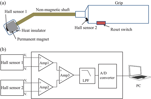
Figure 1.10. (a) Structure of the magnetic probe. (b) Diagram of the driving circuit.
Download figure:
Standard image High-resolution imageAs shown in figure 1.10(b), in the drive circuit, outputs from the two sensors are amplified and converted to a digital signal with an AD converter. Because the detected magnetic field is weak, the signal is easily affected by drift. A button to reset the drift is provided, and drift can be eliminated during operation by using the reset button as needed.
Figure 1.11 shows an updated prototype magnetic probe. The drive circuit and battery are housed inside the grip, and the device is designed to fit entirely in the hand. Magnetic flux density is shown on a small display in units of microtesla. A speaker is built in, and changes in the sound notify the user when MNPs are detected. Equipping the device with a speaker enables physicians to know when MNPs are detected, without having to check a screen during surgery. The sound output is a continuous pulse that changes in frequency, pulse length, and pulse interval according to the output of the magnetic sensor.
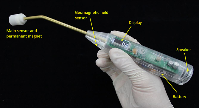
Figure 1.11. Prototype magnetic probe.
Download figure:
Standard image High-resolution image1.6. Clinical applications
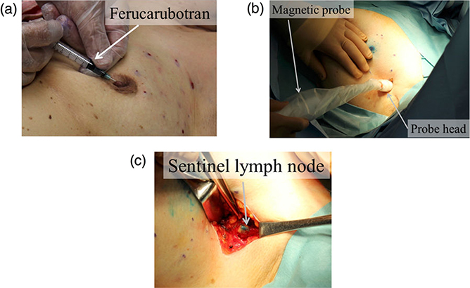
Identification of SLNs in breast cancer patients was performed using a magnetic probe. There were six patients with an average age of 69 ± 7. After administering a general anesthesia, 1.6 mL of a MNP solution (Resovist) and a blue dye (1% patent blue, 3 mL) were injected subcutaneously to the areola. Figure 1.12(a) shows how these injections were administered. To ensure sufficient flow of MNPs and dye into the lymph ducts, the breasts were massaged for several minutes. After making an incision at the axilla, the magnetic probe was used to search for SLNs. Then, as shown in figure 1.12(b), the tip of the magnetic probe was inserted into the surgical field. SLNs were identified by combining visual observation of dye and detection of MNPs, as shown in figure 1.12(c); the identified lymph nodes were excised. To confirm whether MNPs had accumulated in an excised lymph node, the magnetic probe was applied to the lymph node and the measured value of magnetic flux density was recorded. Because there are multiple SLNs in many cases, we explored the axial area using the magnetic probe to confirm that there was no remaining magnetic field response. To determine whether cancer had metastasized to the SLNs, rapid diagnoses were made during surgery using HE staining of frozen sections. Additionally, to quantify the number of MNPs accumulated in the excised lymph nodes, a vibrating sample magnetometer was used to measure the magnetic moment.
Figure 1.12. Clinical test using the handheld magnetic probe; (a) injection of magnetic tracers around the subareolar region, (b) transcutaneous detection of the SLNs before incision, and (c) SLNs detection and excision in the axilla after incision. In the injection phase (a), the blue dye tracer is injected at the same location after the injection of the magnetic tracer [16].
Download figure:
Standard image High-resolution image
In four out of the six patients, accumulation of the MNPs in the SLNs was confirmed and detection with the magnetic probe was successful. Metastasis in the SLNs was observed in one patient. The SLNs where metastasis was observed were among those nodes successfully detected by the magnetic probe. The magnetic flux density value observed using the magnetic probe in the MNPs was 11 ± 5 μT. A number of MNPs proportional to 5 ± 3 μL of solution was contained in the excised lymph nodes.
Some of the MNPs administered subcutaneously to the areola remained in the area. Because the MNPs are a dark brown color, it is also possible that the administration site will develop a dark brown color. Additionally, it has also been reported that residual MNPs can create MRI artifacts. The presence of residual MNPs in patients has been found after periods of more than a year [29]. MRI artifacts such as these may affect the monitoring of patient progress following surgery. One method of avoiding this problem is to use MNPs only in patients who will have the administration site, such as the areola, excised.
We have discussed the usefulness of MNPs primarily in relation to SLNB of breast cancer. It is known that metastasis via the lymphatic system occurs in other types of cancer affecting various organs; the usefulness of SLNB in these conditions has been reported. Some examples of these conditions include stomach cancer, skin cancer, uterine cancer, and cancer of the head and neck. Regarding skin cancer, the usefulness of SLNB using MNPs has already been reported [30]. In the future, we expect further applications in other forms of cancer.
1.7. Conclusions and future prospects
This chapter describes the characteristics and current state of techniques for using MNPs as a tracer in SLNB. Because the number of people who develop breast cancer is high, it is treated even at medical institutions that do not have facilities that administer RI tracers. We expect that MNPs could replace RI as a tracer in such medical institutions. MNPs are superior to dye in that they can be objectively detected using a magnetic probe and are detectable even at a depth of approximately 1 cm.
Although a variety of devices are reported as being capable of detecting MNPs, a handheld magnetic probe can be used in the operating room. Devices using alternating magnetic fields have already been applied in practical settings. Because little energy is consumed when using a static magnetic field generated by a permanent magnet, entire electronics, including the drive circuit and battery, can be housed within the grip.
One major challenge moving forward is to make the sensor more sensitive so as to increase the detection distance of the magnetic probe. In recent years, the sensitivity of magnetic sensors that operate at room temperature has increased rapidly. For example, there have been reports on the development of magnetic probes using magnetic tunnel junction devices [31]. Additionally, fluxgate sensors, optical pumping magnetometers, and diamond nitrogen-vacancy (NV) magnetic sensors operate without coolant and are highly sensitive, which means that they may be applied to the detection of MNPs.
References
- [1]Veronesi U et al 1997 Lancet 394 1864–7
- [2]Noguchi M, Miwa K, Michigishi T, Yokoyama K, Nishijima H, Takanaka T, Kawashima H, Nakamura S, Kanno H and Nonomura A 1997 Breast Cancer 4 143
- [3]Kim T, Giuliano A E and Lyman G H 2006 Cancer 106 4–16
- [4]Wetzig N, Gill P G, Espinoza D, Mister R, Stockler M R, Gebski V J, Ung O A, Campbell I and Simes J 2017 Ann. Surg. Oncol. 24 1064–70
- [5]Radovanovic Z, Golubovic A, Plzak A, Stojiljkovic B and Radovanovic D 2004 Eur. J. Surg. Oncol. 30 913–7
- [6]Hung W K, Chan C M, Ying M, Chong S F, Mak K L and Yip A W 2005 Br. J. Surg. 92 1494–7
- [7]Meyer-Rochow G Y, Martin R C and Harman C R 2003 ANZ J. Surg. 73 815–8
- [8]Douek M 2014 Ann. Surg. Oncol. 21 1237–45
- [9]Rubio I T, Diaz-Botero S, Esgueva A, Rodriguez R, Cortadellas T, Cordoba O and Espinosa-Bravo M 2015 Eur. J. Surg. Oncol. 41 46–51
- [10]Thill M, Kurylcio A, Welter R, van Haasteren V, Grosse B, Berclaz G, Polkowski W and Hauser N 2014 The Breast 23 175–9
- [11]Ahmed M, Purushotham A D and Douek M 2014 Lancet Oncol. 15 e351–362
- [12]Ahmed M and Douek M 2013 Biomed. Res. Int. 2013 281230
- [13]Zada A et al 2017 Br. J. Surg. 103 1409–19
- [14]Fujita M et al 1996 J. Magn. Reson. Imaging 6 472–7
- [15]Kato N, Takahashi M, Tsuji T, Ihara S, Brautigam M and Miyazawa T 1999 Invest. Radiol. 34 551–7
- [16]Sekino M et al 2018 Sci. Rep. 8 1195
- [17]Pouw J J, Ahmed M, Anninga B, Schuurman K, Pinder S E, Hemelrijck M V, Pankhurst Q A, Douek M and ten Haken B 2015 Int. J. Nanomedicine 10 1235–43
- [18]Kuwahata A, Kaneko M, Chikaki S, Kusakabe M and Sekino M 2018 AIP Adv. 8 056713
- [19]Ahmed M et al 2016 Nanomed. Nanotechnol. Biol. Med. 12 1045–52
- [20]Shiozawa M, Kobayashi S, Sato Y, Maeshima H, Hozumi Y, Lefor A T, Kurihara K, Sata N and Yasuda Y 2014 Breast Cancer 21 394–401
- [21]Motomura K, Izumi T, Tateishi S, Tamaki Y, Ito Y, Horinouchi T and Nakanishi K 2016 Br. J. Surg. 103 60–9
- [22]Gleich B and Weizenecker J 2005 Nature 435 1241–7
- [23]Kratz H, Taupitz M, Ariza de Schellenberger A, Kosch O, Eberbeck D, Wagner S, Trahms L, Hamm B and Schnorr J 2018 PLoS One 13 e0190214
- [24]Tanaka S, Hirata A, Saito Y, Mizoguchi T, Tamaki T, Sakita I and Monden M 2001 IEEE Trans. Appl. Supercond. 11 665–8
- [25]Shiozawa M, Lefor A T, Hozumi Y, Kurihara K, Sata N, Yasuda Y and Kusakabe M 2013 Breast Cancer 20 223–9
- [26]Ookubo T, Inoue Y, Kim D, Ohsaki H, Mashiko Y, Kusakabe M and Sekino M 2016 Electron. Commun. Jpn. 99 13–21
- [27]Kuwahata A, Chikaki S, Ergin A, Kaneko M, Kusakabe M and Sekino M 2017 AIP Adv. 7 056720
- [28]Kaneko M, Ohashi K, Chikaki S, Kuwahata A, Shiozawa M, Kusakabe M and Sekino M 2017 AIP Adv. 7 056713
- [29]Pouw J J, Grootendorst M R, Bezooijen R, Klazen C A, De Bruin W I, Klaase J M, Hall-Craggs M A, Douek M and Ten Haken B 2015 Br. J. Radiol. 88 20150634
- [30]Anninga B et al 2016 Ann. Surg. Oncol. 23 2070–8
- [31]Cousins A, Balalis G L, Thompson S K, Forero Morales D, Mohtar A, Wedding A B and Thierry B 2015 Sci. Rep. 5 10842