

Abstract
A lossless acoustic half-bipolar cylindrical cloak that has an exposed bottom is considered. Here, we show that a cloak that includes a complementary region including a negative-index medium inside of the cloaking shell works in the illumination direction independently even in the presence of the exposed bottom of the structure. This is due to the fact that the phase velocity of the wave in the normal direction can be cancelled in the presence of a boundary containing a negative-index medium that reduces scattering significantly.
Export citation and abstract BibTeX RIS
1. Introduction
Acoustic cloaking has been of substantial interest.1–7) Most of the existing works1–7) on acoustic cloaking are based on using the analogy between acoustic equations and transverse electric (TE) polarizations of two-dimensional (2D) electromagnetic field equations. However, it is found that the cloaking performance of an electromagnetic cloak for transverse magnetic (TM) polarizations is superior to that for TE polarizations because the scattering coefficients for the latter do not vanish completely.8,9) Moreover, there have been studies of electromagnetic cloaks with partially enclosed cloaking structures.10–14)
Previously, we studied15) a lossless acoustic cloak using the analogy of acoustic equations and TM polarizations of electromagnetic field equations, and showed that the acoustic cloak with both the cloaking shell and complementary media shows illumination-direction-independent cloaking performance. The material properties for the acoustic cloak were obtained by comparing 2D Maxwell's equations in the TM polarization with acoustic field equations for general curvilinear coordinates with the effective medium theory.16) In this work, we consider a lossless half-bipolar cylindrical acoustic cloak with an exposed bottom. This study is motivated by the possible shapes of submarine tails,17,18) forward and aft, which are hypothetically close to half-bipolar cylindrical shape. Under high-frequency sonar illumination, the reflections from those fins would be more pronounced as in the case of aircraft wings and fins. Another motivation for the study of half-bipolar cylindrical geometry is the minimum use of cloaking materials to achieve stealth performance.
Here, we show that a cloak that includes a complementary region including a negative-index medium inside the cloaking shell works even in the presence of the exposed bottom of the structure. A dispersive full-wave finite-difference time-domain (FDTD) method9) is employed for numerical analysis.
2. Theoretical model
For a non-viscous uncharged fluid with zero shear modulus, the linearized Euler field equations of motion for the anisotropic but diagonal mass density  , the scalar pressure p, and the vector fluid velocity v can be written as1,2,19)

where  is the fluid bulk modulus. By comparing with Maxwell's equations for TM polarizations
  , we obtain material parameters for the acoustic cloak by the variable change15)

We consider the cloak in the bipolar cylindrical coordinates shown in Fig. 1. The bipolar coordinates  and the Cartesian coordinates
  are related to each other by20)


Here, a is the focal length. In the following, we are primarily interested in the cloaking geometry generated by


The family of circles defined by Eq. (5) with centers on the y-axis at the point x = 0, y = a cot σ, the radii of circles being a csc σ, is obtained from Eq. (3) and  .
.
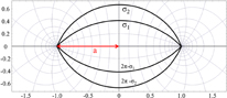
Fig. 1. Bipolar cylindrical coordinate system. The black lines represent constant σ contours and the length of the red arrow pointing at the center indicates the half distance a between focal points. The region between σ1 and σ2 is the cloaking device.
Download figure:
Standard image High-resolution imageIn the case of a full-bipolar cylindrical cloak, we set the region for the invisibility device as  and the combined region in which an object to be cloaked is set to σ1 < σ < 2π − σ1. The map that transforms the region for the hidden object into a line is defined by


where the primed coordinates are for the empty curved space-time and the unprimed ones are for the physical space-time.
On the other hand, for the half-bipolar cylindrical cloak, we use only the family of circles in the upper half plane of the y-axis, y ≥ 0. In other words, we set the region of the invisibility device as {σ2 ≤ σ ≤ σ1} and the region in which an object to be cloaked is set to σ1 ≤ σ ≤ π. The map that transforms the region for the hidden object into a line is defined by


The constitutive parameters for the cloak are obtained in terms of the mixed tensors (Appendix A)15)
for σ2 ≤ σ ≤ σ1, indicating that the bottom of the structure is not covered by the cloaking material. To implement the two-dimensional FDTD method, we transform the constitutive parameters (3) obtained for the bipolar cylindrical coordinates into the constitutive tensors in the Cartesian coordinates using the unitary transformations (Appendix B).9)
Recently, we have considered a full-bipolar acoustic cloak15) containing both the conventional cloaking shell, which compresses the inner structure into a line segment, and the complementary media9,12,21) containing the negative-index material. The negative acoustic metamaterial has been studied both theoretically22) and experimentally.23,24) The key design feature is that the inner region filled with the rigid scatterer (RG), which is σ1 < σ < 2π − σ1 for a bipolar cylindrical cloak, should be replaced by complementary media. The complementary region is separated into two symmetrical regions along the symmetry axis, one region filled with air and the other filled with an isotropic complementary medium with  . It was shown that, for the lossless acoustic cloak, the illumination-direction-independent cloaking can be achieved using the structure with the compressed geometry and complementary media.15)
We extend our previous results for the lossless full-bipolar cylindrical cloak to the half-bipolar cylindrical cloak where the cloaking shell covers only the upper structure and the bottom of the cloak is exposed without the cloaking shell. In this work, the region σ1 < σ < π, which would have been filled with the RG in the ordinary half-bipolar cylindrical cloak shown in Fig. 2(a), should be replaced by the negative-index medium and air [Fig. 2(b)]. This region is separated into two along the symmetry axis, one region filled with air [(π + σ1)/2 < σ < π] and the other region [σ1 < σ < (σ1 + π)/2] filled with an isotropic negative-index medium with εr = μr = −1, as shown in Fig. 2(b).

Download figure:
Standard image High-resolution image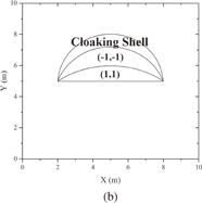
Fig. 2. (a) Bipolar cylindrical half cloak with vertically located cloaking shell in the region  and RG region
  . (b) Bipolar cylindrical half cloak in which the RG region is replaced by the complementary media that consist of free space and negative-index medium with
  .
.
Download figure:
Standard image High-resolution image3. Numerical results and discussion
We consider the acoustic pressure distribution p plane-wave sources that illuminate the two-dimensional σ-axis mapped acoustic bipolar cylindrical half cloak, where the operational frequency is f = 1 KHz and the wavelength is λ = 1.5 m with the use of a low-frequency active sonar system in mind. We have assumed that the speed of sound in the saline water is 1,500 m/s. We have used the FDTD cell size of Δx = Δy = λ/300. The temporal discretization step is taken following the Courant stability condition25–27) by setting Δt = Δx/2c0 (= 1.67 µs), where c0 is the velocity of sound in saline water. The total computational workspace is set to 5.76 million cells (2400 × 2400), including absorbing boundary conditions with perfectly matched layers (PMLs)15) whose width consists of 200 cells. For the σ-axis mapped cloak, we set the inner ellipse σ1 = 0.75π, the outer ellipse σ2 = 0.5π, and the semi-focal distance a = 3 m, and the rigid scatterer (RG) is assumed to be located inside the region between  and π. The total elapsed time of plane-wave propagation is taken as 18,000 steps (≈3 ms). We have used the background inverse modulus and the density of saline water at T = 286 K, which are given by
  [kg/(m·s2)]−1 and ρ0 = 1026 kg/m3, respectively. This cloak is mapped to a line segment with a length of 6 m. This means that the inner space of the cloak shrinks to a line segment. The pressure distribution waves from the outside experience only this line segment. The inner space filled with the RG would be a RG line segment.
In Fig. 3(a), we consider the case of the p-wave propagating with the operational frequency f = 1 kHz along the positive x-direction without the complementary media. In Fig. 3(b), we consider the case of the p-wave propagating with the operational frequency f = 1 kHz along the negative y-direction without the complementary media. In Fig. 3(c), we consider the case of the p-wave propagating with the operational frequency f = 1 kHz along the positive y-direction without the complementary media. In Fig. 3(a), the acoustic cloak is observed to work, but there are shadowing effects on the fields behind the cloaking shell along the direction of wave propagation because of the exposed bottom. The reason why the acoustic cloak works for the incident wave propagating in the positive x-direction can be traced to the fact that the model for the acoustic cloak is derived from the electromagnetic cloak for the TM mode. In the case of the TM mode, it was shown8,9) that, for the wave propagating in the positive x-direction, the boundary condition within the PEC lining at the interior surface eliminates the even scattering coefficients and the incident angle eliminates the odd scattering coefficients. In both Figs. 3(b) and 3(c), it is found that, in both cases, the cloak does not work because of the exposed bottom of the structure.
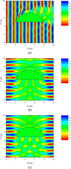
Fig. 3. p-Wave field distributions with operation frequency of 1 kHz when an acoustic half-bipolar cylindrical cloak is exposed to p-wave illumination with different incident axes: (a) x-direction, (b) negative y-direction, and (c) positive y-direction. In these cases, there are no complementary media and half of the focal distance a is 6 m.
Download figure:
Standard image High-resolution imageIn Figs. 4(a)–4(c), the distributions of p-waves propagating along the positive x-direction, the negative y-direction, and the positive y-direction, respectively, are depicted for the operation frequency of 1 kHz for a lossless bipolar cylindrical half cloak with lossless complementary media. From Figs. 3 and 4, one can see that the acoustic cloak is observed to work only when the complementary media are inside the cloak. When the acoustic waves are incident from medium 1 to medium 2, the following boundary conditions must be satisfied:19,28)


independently of whether or not the media are right-handed (positive index) or left-handed (negative index). Here, the subscripts t and n denote the transverse and normal components with respect to the interface, respectively. From Eq. (9), the transverse components of v maintain their directions regardless of the handedness of the two media. As for the normal components, the same direction is maintained only if the two media are of the same handedness, which is also observed in the case of the k vector. For example, one can easily show that

which implies that the phase velocity of the wave in the normal direction can be cancelled if medium 2 is left-handed or a negative-index medium and scattering will be reduced significantly. In Fig. 4(c), the wave is incident on the exposed bottom of the structure and one can see that owing to the presence of complementary media, cloaking works even in this case. Thus, this type of cloak is also expected to work well in the illumination direction independently even for the acoustic wave incident on the exposed bottom.

Fig. 4. p-Wave field distributions with operation frequency of 1 kHz when an acoustic half-bipolar cylindrical cloak with complementary media is exposed to p-wave illumination with different incident axes: (a) x-direction, (b) negative y-direction, and (c) positive y-direction. In these cases, half of the focal distance a is 6 m.
Download figure:
Standard image High-resolution image
4. Conclusions
We consider a lossless acoustic cloak in half-bipolar cylindrical shape with an exposed bottom. We also consider a cloak, which includes a complementary region including a negative-index medium inside the cloaking shell. The material parameters for the acoustic cloak are first obtained by comparing two-dimensional electromagnetic wave equations for TM polarizations and acoustic field equations. The permittivity and permeability tensors for the corresponding electromagnetic fields are first obtained by using an effective medium approach of general relativity. The dispersive FDTD method is used to verify the performance of these cloaking structures numerically. It was shown that the cloak with the complementary media works in the illumination direction independently even in the presence of the exposed bottom of the structure.
Acknowledgement
This work was supported by the Global Frontier Program of MSIP/NRF 2014M3A6B3063706.
Appendix A: Derivation of constitutive parameters
From

for half-bipolar cloak, we obtain the metric tensor  as15,16)
for ![$\sigma' \in [\sigma _{2},\pi ]$](https://content.cld.iop.org/journals/1347-4065/57/5/057301/revision1/RP170377if017.gif) , with
, with
Then, the permittivity tensor εij = μij is given by
for ![$\sigma' \in [\sigma _{2},\pi ]$](https://content.cld.iop.org/journals/1347-4065/57/5/057301/revision1/RP170377if018.gif) .
.
Moreover, we obtain the constitutive parameters in terms of mixed tensors:
for ![$\sigma' \in [\sigma _{2},\pi ]$](https://content.cld.iop.org/journals/1347-4065/57/5/057301/revision1/RP170377if019.gif) .
.
Appendix B: Constitutive parameters in Cartesian coordinates
To implement the two-dimensional FDTD method, we need to transform the constitutive parameters obtained for the bipolar cylindrical coordinates into the constitutive tensors in the Cartesian coordinates using the following unitary transformations:9)

where
with  . The parameters Ω1 and Ω2 for different cylindrical coordinate systems are given in Table B·I. From Eqs. (B·1) and (B·2), one can easily see that the permittivity and permeability tensors have only diagonal components. Thus, the permittivity and permeability tensors can be written as
  and
and  , respectively, in any cylindrical coordinate system. We also denote ε0 and μ0 as the vacuum permittivity and vacuum permeability, respectively.
Table B·I. Parameters for unitary transformation from various cylindrical coordinate systems to the Cartesian coordinate system.
Bipolar cylindrical coordinates  |
Elliptic cylindrical coordinates  |
Circular cylindrical coordinates  |
Parabolic cylindrical coordinates  |
|
|---|---|---|---|---|
| Ω1 | −sin σ sinh τ | sinh u cos v | cos θ | σ |
| Ω2 | cos σ cosh τ − 1 | cosh u sin v | sin θ | τ |