
Abstract
We have theoretically investigated the spin Hall magnetoresistance (SMR) and Rashba–Edelstein magnetoresistance (REMR), mediated by spin currents, in a ferrimagnetic insulator/nonmagnetic metal/heavy metal system in the diffusive regime. The magnitude of both SMR and REMR decreases with increasing thickness of the interlayer because of the current shunting effect and the reduction in spin accumulation across the interlayer. The latter contribution is due to driving a spin current and persists even in the absence of spin relaxation, which is essential for understanding the magnetoresistance ratio in trilayer structures.
Export citation and abstract BibTeX RIS

Content from this work may be used under the terms of the Creative Commons Attribution 4.0 license. Any further distribution of this work must maintain attribution to the author(s) and the title of the work, journal citation and DOI.
Magnetoresistance effects are important for applications in sensor and memory devices and for investigation of spin-dependent transport.1–3) Recently, a new type of magnetoresistance has been demonstrated, in which a spin current generated via spin–orbit coupling from an applied charge current plays a central role.4–12) The generated spin current interacts with magnetization and magnetic field and changes its magnitude.6,8,11,13) When the spin current is converted back to a charge current by spin–orbit coupling,14,15) the spin-current transport modulates the conductivity of the system, and then gives rise to magnetoresistance. This spin-current-induced magnetoresistance is now recognized as an indispensable tool for investigating the spin transport in ferromagnetic material/metal heterostructures.16–19)
The spin Hall magnetoresistance (SMR) refers to the resistance change due to the spin current generated by the spin Hall effect (SHE), which interacts with a ferromagnetic material.4,6) Typically in materials consisting of heavy metals such as Pt and W,4,9) a spin current is induced by an applied charge current, jc, due to the SHE. This spin current propagates in the material and forms spin accumulation,  , around the system edges.20) When
  acts on a ferromagnetic material, it exerts spin transfer torque on the magnetization m, which is given by13)
Here, the spin current is defined to be positive when it flows out of the F layer, and e > 0, Gr, m, and  respectively denote the elementary charge, the real part of the mixing conductance per unit area, and the magnetization unit vector, the spin accumulation at the interface. Since
  is absorbed by the magnetization, the resultant spin accumulation
  decreases, which results in the reduction in back-flow spin current and thus the additional charge current due to the SHE (Fig. 1). As
  depends on the magnetization direction, the spin-current absorption finally appears as a magnetoresistance effect, under which the total conductivity σ shows a different dependence on m from the conventional anisotropic magnetoresistance,6) i.e.,
where n, σ0, and ΔσSMR respectively denote the unit vector normal to the junction interface and the conductivities insensitive and sensitive to the magnetization.

Fig. 1. Schematic illustration of the F/N/H trilayer structure and the effects of the magnetoresistance induced by spin currents. By the spin–charge conversion effect in the system, the applied charge current jc (yellow arrow) forms the spin accumulation  (blue arrow) at the interface. The stationary distribution of
  depends on the orientation of m (red arrow) due to the spin transfer torque at the F/N interface as in Eq. (1). The spin transfer torque is maximal when
  (left part) and absent when
  (right part). The magnitude of
  differs under these configurations of m. The difference in
  results in a different amount of the additional charge current
  induced by the reciprocal process of the spin–charge conversion in the system, which is observable as magnetoresistance. This magnetoresistance effect relies on the spin transport between the conversion layer and the interface of the F layer.
Download figure:
Standard image High-resolution imageIn the context of SMR research, an interlayer with a large spin-diffusion-length is often inserted between the ferromagnetic material and heavy metal layers to distinguish the SMR from the static magnetic proximity effect.4,5,21) For example, the effects of Cu and Au insertion were examined in ferrimagnetic insulator yttrium iron garnet (Y3Fe5O12: YIG)/heavy metal Pt bilayer systems, and the existence of the SMR has been confirmed. However, the SMR magnitude decreases more rapidly than expected even when a current shunting effect is considered. Although such trilayer SMR provides a versatile method to extract spin diffusion length,22) an analytic expression for quantitative interpretation has not yet been obtained.
In this letter, we derive the interlayer thickness dependence of the SMR in the diffusive regime based on the spin diffusion equation and magneto-circuit theory,1,13) and show that the intrinsic magnitude of the SMR decreases as a result of spin-current transport over the trilayer structure. We consider a system composed of a ferrimagnetic insulator (F), a nonmagnetic metal (N), and a heavy metal (H) used for converting a charge current to a spin current. We find that the intrinsic magnitude of the SMR decreases even when the spin relaxation in the N layer is negligibly small. This is due to the reduction in the spin accumulation for driving spin transfer torque. In addition to the SMR, we also calculated the recently observed Rashba–Edelstein magnetoresistance (REMR), caused by spin–charge conversion at the N/H interface,12,15,23,24) because it is also affected by the spin accumulation reduction. The derived expression for the trilayer structure will be useful for understanding the spin-current-induced magnetoresistance effects.
The system coordinate is shown in Fig. 1. The layers are stacked in the z-direction, and we assume translational symmetry in the xy plane. The thicknesses of the F, N, and H layers are dF, dN, and dH, respectively. The N/H interface is at z = 0 and the F/N interface z = −dN. Hereafter, we will use the superscript and subscript  to represent the corresponding quantity in the α layer. In this F/N/H system, we calculated the distribution of spin accumulation
  and spin current flowing in the z-direction
  with its vector direction representing its spin polarization using the diffusion equation
  , where λα is the spin diffusion length.1) We imposed the boundary conditions with Eq. (1) and
  at the F/N interface (z = −dN), zero spin current at the H surface (z = dH), and
  at the N/H interface. For the SMR, continuity of
  is assumed at the N/H interface and, for the REMR, the derived condition in Eq. (9) is assumed. The spin current in the α layer is given by6)

where the vector represents the spin polarization, and σα denotes the conductivity.  represents the SHE-induced spin current, where
  denotes the spin Hall angle, z the unit vector of the z-axis, and E the applied electric field. We assumed
  because
  , which is proportional to ΔσSMR,6) is smaller in the N layer in experiments than in the H layer.4,5,21)
The SMR magnitude is determined from the difference in the magnitude of the spin current flowing through the N/H interface with  on (
on ( ) and off (
 ) [cf. Eq. (1)]. In the trilayer structure, this spin current in the N layer is given by

where  .
.  denotes the effective mixing conductance between the F and H layers in the trilayer configuration F/N/H.
  is smaller than Gr, so the effective spin transfer torque on the F layer is reduced, which in turn reduces the SMR magnitude. This reduction originates from (i) the decay of spin current and (ii) the reduction in
  for driving js in the N layer. Although the former is partially considered in the earlier analysis,4,5) the latter is not. The contribution from (ii) can be clearly recognized in the no-spin-relaxation limit (λN ≫ dN), where we obtain
  , which still shows the apparent dependence of
  on the N layer. In this limit, Eq. (3) leads to an analogous relation to Ohm's law, given by
  . Therefore, as dN increases, the magnitude of
  becomes smaller than that of
  as long as
  . In Fig. 2, we show a typical profile of
  along the z-axis and
  generated by the SHE in the F/N/H system with and without
  (
( and
and  ). As one can see, when the absorption is introduced, μs for driving js decreases with js propagation, and the dependence of
  on m becomes weaker than that in the bilayer system [see Fig. 2(a)]. In the above calculation,
  is self-consistently determined by the condition in the H layer:
and  .
.  (
( ) is realized by setting
  (
( ).
).
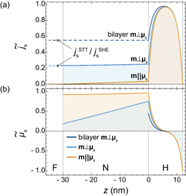
Fig. 2. z profile of the normalized magnitude of the spin current  (a) and the spin accumulation
  (b) for an F/N/H system with dN = 30 nm and dH = 12 nm, where
  . By assuming an YIG/Cu/Pt trilayer, Gr = 5.0 × 10¹⁴ m−2·Ω−1, σN = 1.0 × 10⁷ m−1·Ω−1, λN = 100 nm, σH = 1.2 × 10⁶ m−1·Ω−1, λH = 1.5 nm, and dH = 12 nm are used.4) The gray curve shows the result for the F/H bilayer (dN = 0 nm) with
  and the blue (orange) curve shows that for the trilayer with dN = 30 nm and
  (
( ).
).
Download figure:
Standard image High-resolution imageThe magnitude of the SMR can be calculated by integrating the additional charge current induced by the inverse SHE,  , and taking the difference between the
  on and off states, i.e.,
The magnetoresistance ratio MR ≡ ΔσSMR/σ0 is given by
where  is the current shunting factor for the SMR. For local magnetoresistance effects, such as the anisotropic magnetoresistance (AMR), its intrinsic magnetoresistance ratio MRint is related to MR in the multilayers via MR = RshuntMRint by considering parallel circuiting.9,12) Obviously, Eq. (8) shows the dependence of MRint on
  and ΓN, which is a distinct contribution from the shunting effect. Since
  holds in typical experiments (see the inset in Fig. 3), MR is approximately proportional to
  and thus is reduced by the spin transport in the N layer. Figure 3 shows that MRint for the SMR depends on the thickness dN. As expected from the discussion in the last paragraph, MRint decreases even when λN ≫ dN. In this regime, ΓN becomes zero and only the effective mixing conductance
  contributes to the SMR, which again shows the importance of the reduction in the spin accumulation across the N layer.
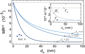
Fig. 3. dN thickness dependence of the magnetoresistance ratio MRint of the SMR calculated at  nm, where the contribution from the current shunting effect is factored out by MRint = MR/Rshunt. Here,
  is assumed and the other parameters are the same as for Fig. 2. The circles represent the experimental results reported.4) The inset shows the calculated values of
  and Γα.
Download figure:
Standard image High-resolution imageThe experimentally reported MRint values of YIG/Cu/Pt trilayers in Ref. 4 are smaller than that expected from Eq. (8). This difference can be attributed to the thickness dependence of the spin diffusion length due to that of the conductance and the spin memory loss effect at the interfaces.25–27) The spin diffusion length decreases at a smaller thickness because of the interfacial scattering,5,12,28) such that the decreased spin-current transmission reduces the SMR magnitude. Similarly, the spin memory loss effect reduces the spin current transmission through the interface. Besides these factors, the spin accumulation reduction considered in this report is important, especially for the larger thickness limit, where most of the spin transport is determined by the bulk properties.
Finally, we apply our calculations to the REMR. Since the REMR appears in F/N/H trilayer structures, it is relevant to the trilayer SMR, which has not been clarified yet.
Under the Rashba–Edelstein effect (REE), an applied electric field induces spin accumulation at the N/H interface, which is given by
where λREE is the REE coefficient, and  and τs denote the density of states and spin relaxation time for the N/H interface, respectively.23) Note that the second term on the right-hand side of Eq. (9), given by Eqs. (5) and (6) with
  , is the contribution of outflow spin currents driven by the REE and is crucial to describing the effect of
  on
on  , i.e., the resultant magnetoresistance. We use Eq. (9) for the boundary condition instead of the continuity of js. Considering the spin-to-charge conversion relation,
  ,15,23) and Eqs. (4), (5), and (9), the magnetoresistance ratio of the REMR is given by
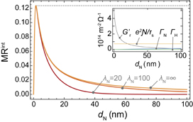
where  denotes the shunting factor for the REMR and σint expresses the sheet conductivity of the N/H interface. As in Eq. (8), MRREMR in Eq. (10) also decreases with increasing dN. Figure 4 shows the calculated thickness dependence of
  . In Ref. 12, the dN dependence of MRREMR is analyzed by assuming constant
  , and the experimental data shows a sharper peak at a smaller dN than the calculated data. This difference can be explained by the
  reduction revealed here. Note that our calculations are for systems with magnetic insulators, but the experiment was performed with a metallic ferromagnet.12) This may affect the MR value, but only a small difference may be expected for the thickness dependence, as in the SMR case.9)
Fig. 4. dN thickness dependence of the magnetoresistance ratio  of the REMR at
  nm, where the contribution from the current shunting effect is factored out by
  . We assumed N = Ag and H = Bi, so that σN = 3.6 × 10⁶ m−1·Ω−1 for the N layer,12) and σH = 7.5 × 10⁴ m−1·Ω−1 and λH = 50 nm for the H layer,29) τs = 3.2 × 10⁻¹⁵ s,
  m−2·J−1, and σint = 2.3 × 10⁻⁴ Ω−1 for the N/H interface are used.12) The REE coefficient is set as λREE = 0.3[1 − exp(−dN/tint)] nm with tint = 0.5 nm to include the suppression of the interface formation.12) For the F/N interface, Gr = 5 × 10¹⁴ m−2·Ω−1 is assumed. The expected maximum MR value is about 0.001 in this calculation, which is in good agreement with the observed value.12) The inset shows the calculated values of
  , Γα, and
  .
.
Download figure:
Standard image High-resolution image
In summary, we formulated the magnitude of the spin-current-induced magnetoresistance effects in a ferrimagnetic insulator/nonmagnetic metal/heavy metal trilayer structure with the spin Hall and Rashba–Edelstein effects. We showed that the spin-current-induced magnetoresistances are sensitive to the spin-current transport in the interlayer, which gives rise to the reduction in the magnetoresistance ratio in addition to the shunting of the applied charge current. Our derived thickness dependence will be useful for quantitatively understanding the spin transport of the inserted layer using the spin-current-induced magnetoresistances.
Acknowledgements
The authors thank J. Kim, K. Kondou, Y. Otani, T. Kikkawa, and G. E. W. Bauer for valuable discussions. This work was supported by PRESTO "Phase Interfaces for Highly Efficient Energy Utilization" and ERATO "Spin Quantum Rectification" from JST, Japan, a Grant-in-Aid for Scientific Research (A) (JP15H02012), a Grant-in-Aid for Scientific Research on Innovative Areas "Nano Spin Conversion Science" (JP26103005) from the Japan Society for the Promotion of Science, NEC Corporation, the Noguchi Institute, and E-IMR, Tohoku University.