

Abstract
We demonstrated a high selective and anisotropic plasma etch of silicon nitride (Si3N4) and silicon carbide (SiC). The demonstrated process consists of a sequence of ion modification and chemical dry removal steps. The Si3N4 etch with hydrogen (H) ion modification showed a high selectivity to silicon dioxide (SiO2) and SiC films without hydro fluorocarbon film deposition which has been used in a conventional Si3N4 etch process. A self-limiting reaction was observed by changing the ion modification and removal step times. The SIMS analyzes indicated that the etch amount of Si3N4 depends on not only penetration depth of H ion but also H concentration in the ion modification step. In addition, we have developed selective etch of SiC with nitrogen (N) ion modification. These results suggest that the ion modification assisted etch enables us to obtain the high selective Si3N4 or SiC film by H or N ion modification, respectively.
Export citation and abstract BibTeX RIS
1. Introduction
With the progress of device miniaturization and increased scale of integration in semiconductor devices, many challenges are now required to overcome the advancement of future etch processing, i.e. selectivity enhancement to mask, more precise profile and critical dimension (CD) loading control. In conventional reactive ion etch (RIE) process, to obtain the desired mask selectivity, profile and CDs, fluorocarbon (FC) or hydro fluorocarbon (HFC) films are generated at the surface of a material, which act as a passivation layer for etch protection.1–10) On the etch of Si3N4, as an example, high selectivity over Si up to 20 can be achieved by a carbon rich passivation layer made on top of the Si substrate.11) However, such a deposition of the FC and HFC films frequently causes the clogging and etch stop issue during the process when the CD size becomes small.12,13) To solve this problem, the atomic layer etch (ALE) technology is utilized, which can be achieved by the cyclic process of inactive etchant adsorption and ion-assisted activation of the etchant.14–20) For example, ALE of SiO2 was demonstrated by the FC radical deposition and Ar ion activation.21,22) Similarly, the independent control over radical and ion flux has also been demonstrated in Si3N4 etch using HFC gas chemistries.23) Although more concise etch control can be obtained via ALE, multiple layers of FC and HFC can be accumulated depending on process recipes adsorption time. The inability to achieve a self-limiting reaction still poses a problem for high precision and clogging free small contacts for future nano-fabrication nodes.
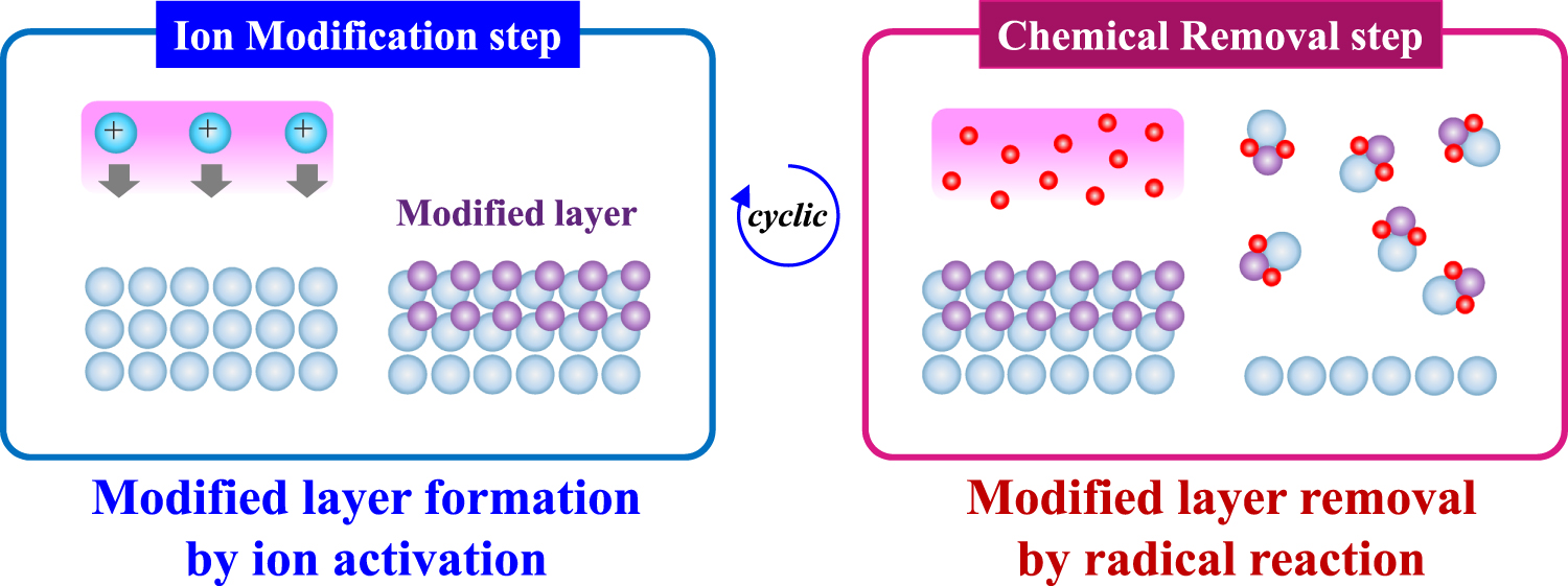
Recently, an alternative method to ALE has been proposed by Refs. 24–28. They demonstrated that Si3N4 was high selectively etched by precisely controlled surface reaction without any adsorption such as HFC or FC radicals, which was achieved via cyclic reaction of H or He ion implantation and subsequently removal step as shown in Fig. 1. They found ion modified surface was selectively etched over the pristine surface by both wet (diluted hydrofluoric acid) and plasma (F-based) etch processes. They also claimed26,27) that the etch amount of Si3N4 film tends to be saturated at a fixed depth of the H ion after enough F removal time, i.e. the self-limiting feature. Moreover, the etch process has the anisotropy since the modification of the film is caused by anisotropic ion irradiation.
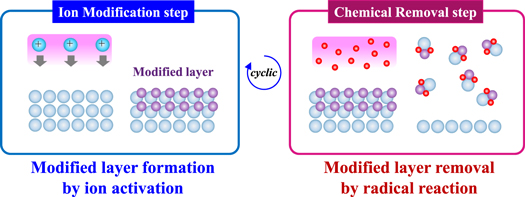
Fig. 1. (Color online) Scheme of etch with ion modification and removal steps.
Download figure:
Standard image High-resolution imageAlthough the aforementioned method demonstrates precise etch control and favorable etch properties, it has only been well studied and characterized using Si3N4. Few studies of the etch method via ion modification have been carried out on other materials. In this work, we demonstrate that the present technique proposed by Ref. 29 can also be applied on silicon carbide (SiC), resulting the highly selective etch of SiC. SiC is also important material in the CMOS fabrication process. For example, selective SiC etch to SiO2 and Si3N4 at narrow patterned CD is required in multi-color-selectivity-patterning. The highly selective SiC etch is attained using a nitrogen (N) ion modification step, rather than an H ion modification step as in the Si3N4 studies. Throughout this paper, we investigate the characteristics of both Si3N4 and SiC etch processes via ion modification and dry chemical to identify self-limiting behavior and determine their selectivities to SiO2 based on the dependence of each step time to etched depth. In addition, we analyze the surface reaction and condition of Si3N4 and SiC after H and N ion modification by secondary ion mass spectroscopy (SIMS) and X-ray photoelectron spectroscopy (XPS) in order to understand the mechanism of the enhancing the etch reactions.
2. Experimental methods
All experiments were carried out using a plasma etch chamber with dual RF generator. In this setup, the source RF and the bottom (bias) RF are applied from the top and bottom electrodes respectively. The top plasma source enables the generation of plasma with high electron density (Ne) and ultra-low bias (Vdc), i.e. ultra-low ion energy (Ei). In this study, the Ei indicates the average value of ion energy distribution. At ion modification step for Si3N4 etch, the main H2 gas plasma at low pressure (30 m Torr) was generated with the bottom RF to control the penetration depth of ion (Ei ∼ 100 eV) and dose amount. In the case of SiC etch, the plasma of N2 was generated for N ion modification. Then at removal step, NF3/H2 based plasma at was generated with the top RF. The modified layer was etched by NF3/H2 based plasma without intense ion bombardment (Ei < 20 eV). The etch process further proceeded by alternatively repeating ion modification and removal steps alternately. The basic modification and removal step times in this study are 15 and 5 s unless otherwise noted. The other experimental condition and parameter was in accordance with the literature.26)
In this study, Si3N4 and SiC grown by low pressure chemical vapor deposition, thermal SiO2 were used to measure the etch amount (E/A) or etch rate (E/R). The film thickness was measured using an ellipsometry. Moreover, the surface of the modified Si3N4 or SiC film is analyzed by ex-situ SIMS, XPS or transmission electron microscope (TEM) to determine the penetration depth of ion. 2 keV CS+ was used as the primary beam for SIMS analysis. The patterned profile and the surface of films were observed using scanning electron microscopy or TEM.
3. Results and discussion
3.1. Si3N4 etch with H ion modification
3.1.1. Characteristics of Si3N4 etch with H ion modification
First we investigated the E/R of Si3N4 at only ion modification step, only removal step and the cyclic process of both step to identify the effect of the H ion modification on the Si3N4 etch (Fig. 2). The E/R means the etch amount of Si3N4 per 1 cycle or each step. In Fig. 2, E/R of the Si3N4 film alternately exposed to H2 plasma and NF3/H2 plasma is over 20 times higher than that exposed to only H2 plasma or NF3/H2 plasma. To understand the etch mechanism, we analyzed the depth profile of H atom concentration in the Si3N4 films by SIMS (Fig. 3). In Fig. 3, the modification and the removal times are 60 s and 5 s, respectively. The SIMS spectra show that the H atom concentration increases from 2 nm to about 10 nm after ion modification. Then, the concentration decreases drastically after the modified Si3N4 film is exposed to F plasma. It was reported that Si–H and N–H bonds in Si3N4 film are induced after H ion is implanted.24) The increase of the H atom concentration in Fig. 3 is estimated to be proportional to the formation of the chemical bonds in Si3N4 film. Moreover, it is assumed that H atom implanted into Si3N4 affects the etch reaction probability and enhances the formation of volatile compounds containing an H atom.30) Therefore, the results of Fig. 2 and Fig. 3 imply the H atom implanted into Si3N4 film is consumed during the etch reaction with F radical and contributes to the marked increase of Si3N4 E/R.

Fig. 2. Si3N4 E/R at each process step.
Download figure:
Standard image High-resolution image
Fig. 3. Depth profile of H concentration by SIMS in Si3N4 etch.
Download figure:
Standard image High-resolution image3.1.2. Self-limiting reaction based on H ion modification
We evaluated the relationship between the etched depth and the penetration depth of H ion to determine if the process has the self-limiting reaction. Figure 4 shows the removal step time dependency of Si3N4 E/R under fixed ion modification time with 15 s. When the removal time increases enough, Si3N4 E/R tends to be saturated. The saturated E/R is approximately 2.3 nm/cycle. The total depth of H ion implantation in Si3N4 film is estimated to be a certain penetration depth of H ion under the fixed ion energy (Ei ∼ 100 eV) in this experiment because the thickness of the implanted ion is a function of ion energy.31) Thus we assume that the saturated E/R in Fig. 4 was caused by the stop of the etch reaction that the ion modified layer of a certain thickness was etched completely with F radical. Based on the saturated E/R, which appears to be a function of the thickness of the ion modified layer, we confirm that the etch process demonstrates self-limiting behavior.

Fig. 4. Removal step time dependency of Si3N4 E/R under fixed ion modification condition.
Download figure:
Standard image High-resolution imageNext, we examined the relationship between the etched depth and H ion dose amount to understand the influence of ion flux on the observed etch behavior. Figure 5 shows a SIMS analysis of the depth profile of the H atom in each Si3N4 film at a fixed ion energy (Ei ∼ 100 eV) when the ion modification step time is increased. The result indicates that the H concentration peak at a value of ∼5 nm as the ion modification step time (be proportional to ion dose amount) is increased. The spectra show that the total depth of H ion becomes deeper as longer modification though we fixed ion energy. Then, we investigated the ion modification step time dependency of Si3N4 E/A under fixed ion energy (Fig. 6). In Fig. 6 the Si3N4 E/A represents the saturated etched depth after long enough removal step time (>30 s per ion modification step), for the same conditions used to collect the data in Fig. 5. The saturated E/A at 60, 180, 360 s in modification step times are about 5.2, 10.2, 12.4 nm, respectively. When the depth of H atom in Fig. 5 is related to the E/A in Fig. 6 at each modification time, the region of H concentration is estimated to be from 5 × 10²¹ to 8 × 10²¹ atoms cm−3. From the results, there appears to be a threshold of H concentration in relation to the etched amount of Si3N4. Thus, the results suggest that the E/A depends on not only penetration depth of H, but also H concentration, that is ion dose amount at the modification step.
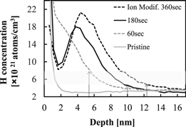
Fig. 5. Modification step time dependency of H depth and concentration by SIMS.
Download figure:
Standard image High-resolution image
Fig. 6. Modification step time dependency of Si3N4 E/A after enough removal.
Download figure:
Standard image High-resolution image3.1.3. Etched profile in Si3N4 etch with H ion modification
We evaluated the etched profile of patterned samples using the previously described method to identify the selectivity of Si3N4 etch to other material. Figure 7 indicates the TEM images of etched profile in Si3N4 etch with H ion modification and removal steps. It is confirmed that the Si3N4 film was starting to be etched from the top of Si3N4 spacer on Si layer and bottom SiO2 layer at 10 and 20 cycle. In particular, E/A of the top of Si3N4 on bottom SiO2 and the sidewall Si3N4 and are more than 25 nm and less than 3 nm at 10 cycle, respectively. Therefore, it is considered that this process has the characteristics of anisotropic etch. At 20% over etch, the Si3N4 spacer was completely removed. Then, the loss of bottom SiO2 layer is less than 2 nm. The loss of Si core is unclear because the height of originated Si core before etch has the maximum variation of 10 nm. The minimal loss of SiO2 indicates a high selectivity towards Si3N4 using depo-free chemistry. (the Si3N4 etch selectivity to SiO2 is over 50).

Fig. 7. TEM images of etched profile in Si3N4 etch with H ion modification.
Download figure:
Standard image High-resolution image3.1.4. Selective Si3N4 etch to SiC and SiO2 with H ion modification
Blanket studies were run using the previously described process on Si3N4, SiC and SiO2 films to further investigate the selectivity of Si3N4 etch via H ion modification. Figure 8 shows the dependence of E/A on cycle number for Si3N4, SiC and SiO2. In the experiments we unified the ion modification step time and removal step time with 15 and 5 s, respectively. In Fig. 8, a high selective Si3N4 etch to SiC, SiO2 was attained at 60 cycles, and the Si3N4 E/R was about 1.0 nm/cycle. The results indicate that H ion modification enables the selective enhancement of Si3N4 etch reaction and does not have a strong influence on SiC, SiO2 etch reaction. As mentioned in Sect. 3.1.1, we attribute the enhanced Si3N4 etch to the formation of the (–H) chemical bonds in the Si3N4 film via H implantation. The lower E/R of SiO2 than the ones of Si3N4 and SiC can be explained by the difference of dissociation energies of each chemical bonding at room temperature, where the energy of Si–O is much higher (799.6 ± 13.4 kJ mol−1) compared with the others; Si–F (576.4 ± 17.0 kJ mol−1), Si–C (447 kJ mol−1), and Si–N (437.1 ± 9.9 kJ mol−1).26,32) While the etch reaction of Si3N4 and SiC with F atom is favorable, the SiO2 etch with F atom hardly occurs thermodynamically. Moreover, it is estimated that SiO2 sputtering with F ion does not occur because Ei at the removal step of this study (<20 eV) was below threshold of sputtering in this study.33) In regards to the slightly enhanced SiC etch via H ion modification, we have yet investigate the underlying cause. The detection of H and the formation of the chemical bonds with H was too difficult to measure with XPS, however, use of in situ Fourier transform infrared spectroscopy (FTIR) can be used to understand the mechanism of the low SiC E/R and is the subject of future work.

Fig. 8. Cycle number dependency of Si3N4, SiC and SiO2 E/A with H ion modification under and removal steps.
Download figure:
Standard image High-resolution image3.2. SiC etch with N ion modification
3.2.1. Characteristics of SiC etch with N ion modification
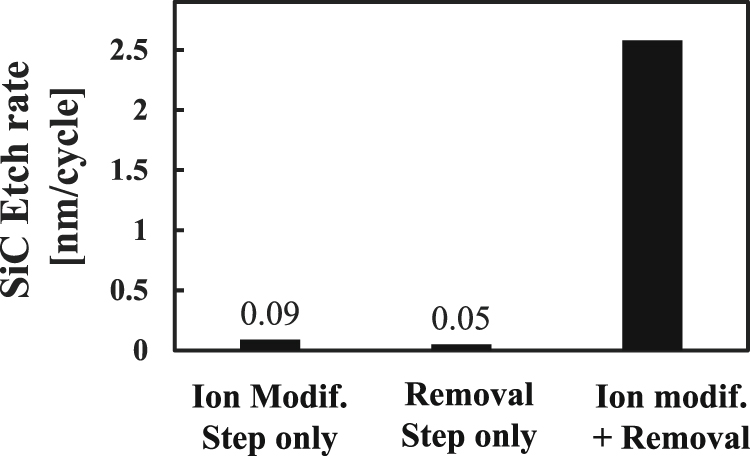
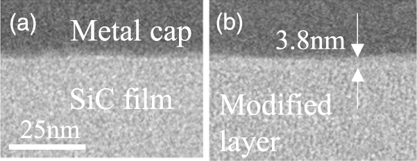
Similar to Si3N4, we used the same principals of the previously described process to evaluate the etch characteristics of SiC. However, we replaced the H ion modification step with an N ion modification step. To begin the studies, we investigated the E/R of SiC at only ion modification step, only removal step and the cyclic process of both step to identify the effect of N ion modification on the SiC etch. Figure 9 shows the SiC E/R at only ion modification step, only removal step and the cyclic process of both step. The rapid increase of the E/R was confirmed as well as the case of SiC etch after the combination of ion modification and removal. Moreover, we observed the surface of pristine SiC film and one after N ion modification with TEM and XPS analysis in order to investigate whether the modification is caused by N ion implantation. Figures 10(a) and 10(b) show TEM images of a pristine SiC film covered with metal coat and a SiC film after N ion modification at 60 s of the modification time and Ei ∼ 100 eV, respectively. In Fig. 10(b), the modified layer with a thickness of 3.5–3.8 nm can be confirmed. This thickness of modified layer is consistent with calculated total depth of N+ or N2+ (3–4 nm) by Monte-Carlo simulation code TRIM (transport of ions in matter).34) From the result of Figs. 10(a) and 10(b), the modification layer seems to be formed with N ion implantation. Figure 11 indicates the N 1 s peaks of the surface on SiC film of Figs. 10(a) and 10(b) by XPS analysis. From the result, the increase of the peak based on the compound containing N (397 eV) is confirmed. The result implies that N ion implanted causes the nitridization and that formation of the (–N) bond in SiC film. According to the evaluation by Ref. 35, it was observed that E/R of SiC film containing N atom (SiCN) is ten times higher than the E/R of SiC film in conventional RIE with NF3 based chemistry. Therefore, it seems that the SiC etch via N ion implantation was enhanced because the SiC film was thought to be modified to a SiCN like film due to the formation of the (–N) bond during the N ion modification step.
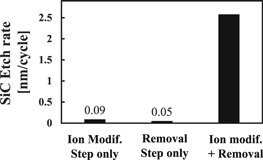
Fig. 9. SiC E/R at each process step.
Download figure:
Standard image High-resolution image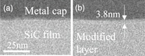
Fig. 10. TEM images of surface of SiC film. (a) Pristine SiC film (b) modified SiC film after N ion modification.
Download figure:
Standard image High-resolution image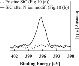
Fig. 11. N1s peak of SiC film after N ion modification with XPS analysis.
Download figure:
Standard image High-resolution image3.2.2. A self-limiting reaction based on N ion modification
To determine if the reaction was self-limiting, as in the case of the H ion modified Si3N4 etch, we evaluated the relationship between the etch depth and the depth profile of N for various SiC films. Figure 12 shows the E/R dependency based on the removal step time at a fixed ion energy (Ei ∼ 100 eV). The results indicate that the E/R tends to saturate (3.8 nm/cycle) upon increase of the removal step time. The total depth of N ion implantation in SiC film was also estimated to be a certain depth based on the fixed ion energy and is hypothesized to cause the saturated E/R when the ion modified layer is completely removed by the F plasma. Similar to the Si3N4 case, we conclude that the saturated E/R is a function of the thickness of the ion modified layer, which demonstrates self-limiting behavior.

Fig. 12. Removal step time dependency of SiC E/A under fixed ion modification condition.
Download figure:
Standard image High-resolution image3.2.3. Selective SiC etch of Si3N4, SiO2 with N ion modification
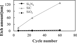
Finally, we investigated the selectivity of SiC etch compared to Si3N4 and SiO2 using N ion modification. Figure 13 shows the dependence of E/A on the cycle number for Si3N4, SiC and SiO2 using the N ion modification step. In the experiments we unified the ion modification step time and removal step time with 15 and 5 s, respectively. In Fig. 13, a high SiC selective etch to Si3N4, SiO2 was attained at 60 cycles, and the SiC E/R was about 2.0 nm/cycle. The results indicate that H ion modification enables the selective enhancement of SiC etch reaction and does not have a strong influence on Si3N4, SiO2 etch reaction. As discussed in Sect. 3.2.2, the enhance of SiC etch reaction seems to be caused by the formation of the (–N) bond in SiC film during N ion implantation. In the case of SiO2 etch, we reason that the low SiO2 E/R are due to the same arguments of the thermodynamics and the threshold energy of sputtering by F ion discussed in Sect. 3.1.4. Besides even if the SiO2 film is modified to SiON like film (closed to Si3N4 film) during N ion implantation, the modified SiO2 E/R is estimated to be low because the non-modified Si3N4 is 0.04 nm/cycle by NF3/H2 plasma at removal steps from the data of Fig. 2 in Sect. 3.1.1. In the case of the Si3N4 etch, we speculate that since the film is already significantly composed of Si and N, the etch reaction becomes retarded due to the fact that no new chemical bonds are formed during the N ion modification step.
Fig. 13. Cycle number dependency of Si3N4, SiC and SiO2 E/A with N ion modification and removal steps.
Download figure:
Standard image High-resolution image
4. Summary and conclusions
In this paper, we have evaluated the etch method using ion modification and chemical dry removal. First, we investigated the characteristics of S3iN4 etch with H ion modification. We hypothesize, based on SIMS analysis, that the marked increase of Si3N4 E/R using the H ion modification step is caused by the formation of (–H) chemical bonds in the Si3N4 film. The SIMS surface analysis was also used to confirm that this process has the characteristics of a self-limiting reaction, similar to ALE, based on the H ion penetration depth and H ion dose amount. Further studies on patterned samples indicated that the etch method not only has high selectivity toward Si3N4 over SiO2 and SiC, but also has the characteristics of anisotropic etch. From blanket studies, the results obtained for patterned samples demonstrate a highly selective etch of Si3N4 over SiO2. We reasoned from a thermodynamic standpoint that H ion modification is difficult in the SiO2 films and is the root cause for the low E/R. SiC blankets showed a slight E/R increase upon H ion modification; however, it was difficult to identify the (–H) influence as detection by XPS is not trivial. Therefore, future efforts will be taken to study the etch mechanism for the H ion implantation into SiC via in situ FTIR.
To put forth new research, a SiC etch process was developed using N ion modification and a dry chemical removal, similar to a Si3N4 etch using H ion modification. A marked increase for the SiC E/R was observed and attributed to the formation of (–N) chemical bonds in the SiC film during the N ion modification step. Validation of such bond formation came from XPS analysis. As in the Si3N4 etch with the H ion modification, the SiC process also demonstrates self-limiting behavior based on the N ion penetration depth. Although we have not investigated the anisotropy and the self-limiting reaction based on N ion dose amount, we speculate that both hold true to the process, like Si3N4 etch via H ion implantation. To confirm such characteristics, it will be necessary that future studies involving patterned samples and SIMS surface analysis. In the evaluation of the SiC etch, the high selectivity over SiO2 and Si3N4 was explained via the difficulty to form new (–N) chemical bonds during the N ion modification step. The high bond dissociation energy of Si–O and the saturation of Si–N bonds of the Si3N4 films cause low E/Rs for both processes.
The success of developing a selective SiC etch via N implantation on the basis of Si3N4 etch via H implantation implies that this etch method has the potential to selectively modify and selectively etch a variety of different materials based on the optimization of the ion modification species. Most importantly, this method has the characteristics of a high selectivity and self-limiting without FC or a HFC protecting film, indicating that the present technique will significantly contribute to the improvement of the nano-fabrication process for the future technology nodes.