

Abstract
We fabricated Gd–Fe/Ta/sub. and W/Gd–Fe/Ta/sub. perpendicular magnetized magnetic wires and investigated current-induced domain wall motion (CIDWM) in them. The propagation field of the Gd–Fe wires is low (∼3 mT), and the wires were found to have a low threshold current density (∼3.1 × 10¹⁰ A m−2) of CIDWM. The directions of the CIDWM in Gd–Fe/Ta and W/Gd–Fe/Ta wires are opposite to each other, indicating that the CIDWM in both wires is driven by spin–orbit torque because the spin Hall torque generated by the Ta underlayer and W cap layer oppose each other.
Export citation and abstract BibTeX RIS
Magnetic domain wall (DW) manipulation using electric current has been an active research topic because of its potential applications in magnetic devices such as new types of memories and logic.1–3) In particular, race-track memory is a novel data storage device based on current-induced domain wall motion (CIDWM) and has potential as a future memory type.1) A number of experimental investigations of CIDWM using perpendicular magnetic wire have been reported.4–33) In our previous studies, we investigated CIDWM using rare-earth-transition metal perpendicular magnetic wires.14–26) Rare-earth-transition metal alloys such as TbFeCo, TbCo and GdFeCo are ferrimagnetic materials with a low saturation magnetization (MS) because rare-earth metals and transition metals have opposite magnetizations. Recently, rare-earth-transition metal alloys have received extensive attention because fast DW motion has been observed at the angular momentum compensation point in these alloys.34,35) Moreover, rare-earth-transition metal alloy magnetic wires have a low threshold current density (Jth) of CIDWM because the Jth strongly depends on MS.31) We have observed that wires of Tb24Co68.4Co7.6 and Tb37Co63, which are Tb-based alloys, have a lower Jth for CIDWM than wires of other perpendicular magnetic materials such as Co/Ni and Co/Pt.4,10,16,19) However, further lower Jth is eagerly demanded for the realization of magnetic memory based on CIDWM. In this study, we investigate the CIDWM in Gd–Fe alloy, which is a Gd-based alloy.
Ta (3.5 nm)/Gd–Fe (8 nm)/Ta (6 nm)/sub. and Ta (3.5 nm)/W (3 nm)/Gd–Fe (8 nm)/Ta (6 nm)/sub. films were fabricated using DC magnetron sputtering. Sample stacks are shown in Fig. 1(a). Gd–Fe alloy layers were fabricated via co-sputtering using Gd and Fe targets. These films were continuously deposited onto thermally oxidized Si substrates. The electric conductance in the Ta cap layer can be ignored because it was oxidized in air. A 5 μm wide patterned wire was fabricated using electron-beam lithography for a lift-off process. The magnetic properties of the wire were characterized by Hall effect measurements and a vibrating sample magnetometer (VSM). The CIDWM in the Gd–Fe wires was observed using a polar Kerr microscope. The compositions of the Gd–Fe wires were estimated using an energy-dispersive X-ray spectrometer. We estimated the Gd content in the Gd–Fe alloy layers to be 29.4 ± 2.2 at%.
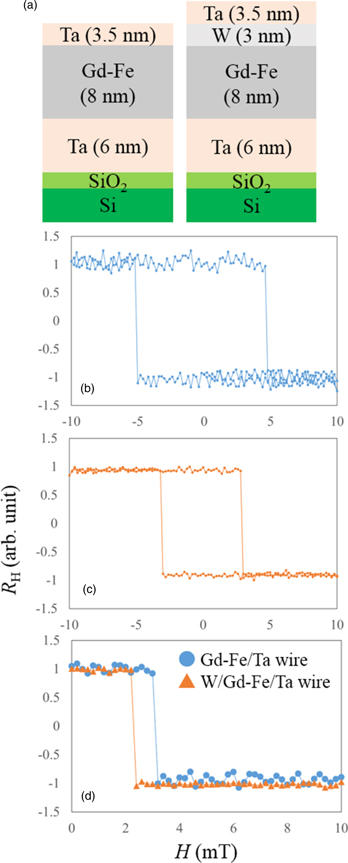
Fig. 1. (Color online) (a) Schematic of the Gd–Fe/Ta and W/Gd–Fe/Ta multilayered films. Hall resistance (RH) of the (b) Gd–Fe/Ta and (c) W/Gd–Fe/Ta wires as a function of the perpendicular magnetic field (H). (d) Initial curves of the Hall hysteresis loops in the present wires.
Download figure:
Standard image High-resolution imageFigures 1(b) and 1(c) show the normalized anomalous Hall resistance (RH) of the Gd–Fe/Ta and W/Gd–Fe/Ta wires as a function of the out-of-plane magnetic field (H). As shown in Figs. 1(b) and 1(c), both the Gd–Fe wires clearly exhibit perpendicular magnetic anisotropy. Figure 1(d) shows the initial curves of RH in the Gd–Fe/Ta and W/Gd–Fe/Ta wires with the DW. The DW in the Gd–Fe wires was introduced by adjusting the external magnetic field. As shown in Fig. 1(d), the fields that can switch magnetization are very low. We define this field as the propagation field (Hp). The values of Hp in the Gd–Fe/Ta and W/Gd–Fe/Ta wires are 3.2 and 2.4 mT, respectively. The MS values of the Gd–Fe/Ta and W/Gd–Fe/Ta wires, as measured using the VSM, are 2.8 × 10⁴ A m−1 and 4.0 × 10⁴ A m−1, respectively.
The DW velocity (v) in both the Gd–Fe wires were measured as follows. First, we applied an out-of-plane magnetic field with a magnitude much higher than the coercivity to saturate the wire magnetization. A DW was then introduced by applying an opposite weak out-of-plane magnetic field with a magnitude lower than the coercivity but higher than that of the DW propagation field. The DW was driven in the wire by a 0.25–1 μs pulse current. DW displacement was observed using a polar Kerr microscope. Finally, v was calculated from the DW displacement and pulse width.
Figures 2(a) and 2(b) show the Kerr images of the Gd–Fe/Ta and W/Gd–Fe/Ta wires before and after a pulse current was applied. As shown in Figs. 2(a) and 2(b), the DW in the wires was clearly moved by the pulse current. Notably, the CIDWM in the Gd–Fe/Ta wires has the same direction as the electric current, whereas that in the W/Gd–Fe/Ta wire has the opposite direction. Recently, numerous experimental investigations on ultrathin wires with an asymmetric layer structure that includes a heavy-metal layer have been reported.13,14,18–33) In these wires, the direction of the DW motion is against the direction of the electron flow, which cannot be explained by conventional spin-transfer-torque-driven CIDWM theories. However, it can be explained by the spin Hall effect (SHE) and the Dzyaloshinsky–Moriya interaction (DMI) (spin–orbit torque) generated by a heavy-metal layer.31) The direction of the CIDWM induced by SHE and DMI is determined by the polarity of the spin Hall angle and by the DMI vector.
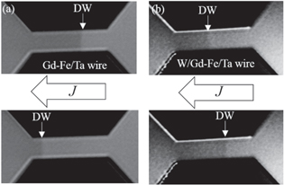
Fig. 2. Kerr images of the (a) Gd–Fe/Ta and (b) W/Gd–Fe/Ta wires. Upper images indicate the initial state. Lower images indicate the states after a 1 μs wide pulse current of 0.7 × 10¹¹ A m−2 (Gd–Fe/Ta) or two 1 μs wide pulse currents of 1.0 × 10¹¹ A m−2 (W/Gd–Fe/Ta) were applied. Arrows indicate the current flow direction.
Download figure:
Standard image High-resolution imageFigures 3(a) and 3(b) show the DW velocities (v) in the Gd–Fe/Ta and W/Gd–Fe/Ta wires as a function of current density (J). The positive v means that the DW moves in the direction of the current flow. As shown in Fig. 3(a), both the Gd–Fe wires have a sufficiently low Jth value. In particular, the value of Jth in the Gd–Fe/Ta wire is ∼3.1 × 10¹⁰ A m−2, which is an order of magnitude smaller than that in conventional magnetic wires such as Co/Pt and Co/Ni multilayered wires.4,10) Moreover, the values of Jth in both wires are smaller than those in Tb–Co wires, which also have low MS values.19) The possible reason for these small Jth values is the difference in Hp. The Jth also strongly depends on the Hp because the SHE-induced effective field can be regarded as a magnetic field.13) Hp values of the Gd–Fe wires are much smaller than that of a Tb–Co wire;19) thus, the Gd–Fe wires have a small Jth.
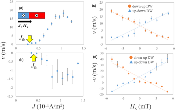
Fig. 3. (Color online) DW velocity (v) in the (a) Gd–Fe/Ta and (b) W/Gd–Fe/Ta wires as a function of current density (J). Positive v means the DW moves in the direction of the current flow. Arrows indicate the threshold current density (Jth). The v in the (c) Gd–Fe/Ta and (d) W/Gd–Fe/Ta wires as a function of longitudinal magnetic field (HX) under J = 0.7 × 10¹¹ A m−2 (Gd–Fe/Ta) or 1.2 × 10¹¹ A m−2 (W/Gd–Fe/Ta). Inset in (a) shows the directions of J and Hx.
Download figure:
Standard image High-resolution imageWe observed the DW velocity in the in-plane field to estimate the polarity of the DMI. Figures 3(c) and 3(d) show the v in the Gd–Fe/Ta and W/Gd–Fe/Ta wires, respectively, as a function of the longitudinal in-plane magnetic field (HX). As shown in Figs. 3(c) and 3(d), the DW velocities are proportional to the HX. The SHE injects a spin current into the ferromagnetic layer and generates a perpendicular effective field on a DMI-induced chiral Néel wall.31) The magnitude and polarity of the DW velocities can be changed by the HX because the SHE-induced perpendicular effective field becomes strong or weak as a result of the enhancement or cancellation of the DMI-induced chiral Néel wall. The same linear dependences of the DW velocity on HX have been observed in investigations of CIDWM by SHE and DMI.30,31) As shown in Figs. 3(c) and 3(d), the polarity of the slope of the up-down (down-up) DW velocity regarding HX in the Gd–Fe/Ta wire is the same as that in the W/Gd–Fe/Ta wire. This result indicates that the DMI vectors in the Gd–Fe/Ta and W/Gd–Fe/Ta wires are oriented in the same direction. In addition, we found that the DMI effective field (HDMI), which corresponds to HX at zero DW velocity, is higher in the Gd–Fe/Ta wire than in the W/Gd–Fe/Ta wire. This result indicates that the DMI generated by the Gd–Fe/Ta layer interface is decreased by that generated by the W/Gd–Fe layer interface.
The spin Hall angles of Ta and W have the same polarity.29) However, the spin Hall torque to move the DW from the top heavy-metal layer is opposite that to move the DW from the bottom heavy-metal layer. Here, we observed magnetization switching in the longitudinal and perpendicular magnetic fields, HX and H, under an applied current, as shown in Fig. 4(a), to reveal the spin Hall torque in the wires. Figures 4(b) and 4(c) show the Hall resistance in the Gd–Fe/Ta and W/Gd–Fe/Ta multilayered wires as a function of H under HX = 70 and 40 mT, respectively. The electric current flows in the ±x direction. As shown in Figs. 4(b) and 4(c), the Hall loops were shifted by the electric current and its direction strongly depends on the current polarity. The shifting of Hall loops is caused by the current-induced effective magnetic field attributed to the spin Hall torque.36) The Gd–Fe/Ta and W/Gd–Fe/Ta wires have opposite current polarity dependence of the direction of shifting. This result indicates that the spin Hall torques are opposite in the Gd–Fe/Ta and W/Gd–Fe/Ta wires. Moreover, the DW driving force in the Gd–Fe layers is attributed to the SHE and DMI, which originates from ferrimagnetic/heavy-metal layer interfaces because the direction of the CIDWM is obviously determined by the heavy-metal layer configuration.

Fig. 4. (Color online) (a) Schematic of the Hall bar. Red arrow shows the direction of J. Hall resistance (RH) of the (b) Gd–Fe/Ta and (c) W/Gd–Fe/Ta wires as a function of the perpendicular magnetic field (H) under an in-plane magnetic field (HX) of 70 mT (Gd–Fe/Ta) or 40 mT (W/Gd–Fe/Ta) and an electric current density (J) of 0.6 × 10¹¹ A m−2 (Gd–Fe/Ta) or 0.5 × 10¹¹ A m−2 (W/Gd–Fe/Ta). Current flow and in-plane magnetic field are in the x direction.
Download figure:
Standard image High-resolution image
In summary, we investigated CIDWM in Gd–Fe/Ta and W/Gd–Fe/Ta magnetic wires. Both the wires have small Hp values compared with that of the Tb–Co wire. In particular, the value of Jth for CIDWM in the Gd–Fe wire is sufficiently small (∼3.1 × 10¹⁰ A m−2). We also found that the direction of CIDWM in the Gd–Fe/Ta wire is opposite to that in the W/Gd–Fe/Ta wire because the spin Hall torques generated by the Ta and W layers are opposite. These results indicate that the driving force of CIDWM in the Gd–Fe/Ta and W/Gd–Fe/Ta wires is attributable to spin–orbit torque.
Acknowledgments
This work was supported by the Nanotechnology Platform Project (Toyota Technological Institute, No. F-17-TT-0028), the Iketani Science and Technology Foundation, the Research Foundation for Electrotechnology of Chubu, and a research grant from The Mazda Foundation.