


Abstract
Five retroreflector arrays currently on the Moon reflect short laser pulses back to Earth, allowing range to be measured. Each array has multiple small corner cubes. Due to variable lunar optical librations of the direction to Earth, the tilted arrays spread return times of single photons in the returned laser pulse, degrading the synthesized multiphoton normal point range accuracy. The Next Generation Lunar Retroreflectors (NGLRs) and MoonLIGHT reflectors currently being fabricated are larger 10 cm single corner cubes that do not spread the pulse. The Lunar Geophysical Network (LGN) mission will place NGLRs at three separated sites on the lunar nearside. The Commercial Lander Payload Service (CLPS) and early Artemis missions will precede the LGN mission. Solutions that include 6 yr of simulated Lunar Laser Ranging (LLR) data to two sites in the north and two in the south show improvement in the uncertainties of many science parameters. Lunar solution parameters include displacement Love numbers h2 and l2, tidal dissipation at several frequencies, fluid-core/solid-mantle boundary (CMB) dissipation, and moment of inertia combinations (C–A)/B and (B–A)/C, with principal moments of inertia A < B < C. Submeter-accuracy coordinates of the new reflectors will result from the first month of well-distributed data. There are benefits other than lunar science: gravitational physics includes the equivalence principle; Earth science includes terrestrial tidal dissipation and ranging station positions and motions; and astronomical constants with GM(Earth+Moon) for the gravitational constant times the mass of the Earth–Moon system. Improvements are illustrated for h2, l2, (C–A)/B, (B–A)/C, equivalence principle, and GM(Earth+Moon).
Export citation and abstract BibTeX RIS

Original content from this work may be used under the terms of the Creative Commons Attribution 4.0 licence. Any further distribution of this work must maintain attribution to the author(s) and the title of the work, journal citation and DOI.
1. Introduction
Several observatories on Earth participate in Lunar Laser Ranging (LLR) to five existing retroreflector sites on the Moon. A short laser pulse is fired toward a reflector site, and the pulse bounces off of the site's corner cubes and returns to the observatory on Earth. The round-trip time of flight gives a measure of the distance since the speed of light has a defined value (Mohr et al. 2016). The mean geocentric distance of the Moon is 385,000 km (Chapront-Touzé & Chapront 1988). Analysis can fit ranges of the past 5 yr at the 1 cm level.
The Lunar Geophysical Network (LGN) mission has the primary goal of understanding the initial stages of terrestrial planet evolution. There are four primary objectives:
(1) Define the interior structure of the Moon.
LLR detects the fluid core. It determines dissipation at the fluid-core/solid-mantle boundary (CMB) and the oblate shape of the CMB.
(2) Constrain the interior and bulk composition of the Moon.
LLR measures strong tidal dissipation in the Moon. It is interpreted to come from a partial melt zone in the lowest 200 km of the mantle. This partial melt zone depends on the lunar thermal state.
(3) Delineate the vertical and lateral heterogeneities within the interior of the Moon as they relate to surface features and terranes.
LLR determines degree-2 displacement Love numbers that depend on the interior structure.
(4) Evaluate the current seismo-tectonic activity of the Moon.
Deep focus moonquakes are triggered by solid-body tides; LLR measures tides.
The nominal LGN mission will include three landing sites on the nearside of the Moon and one on the farside. Each of the three nearside landers will carry two Next Generation Lunar Retroreflector (NGLR) corner cubes.
The Commercial Lander Payload Service (CLPS) missions have more modest goals than the LGN mission, but are intended to land on the Moon years before the LGN landers. The CLPS missions will validate and/or suggest improvements in the design and performance of the NGLRs and their deployments. The optics of the NGLR are the same for LGN and CLPS missions, but the LGN lander will have an arm to deploy and anchor an NGLR in the surface. The first NGLR is scheduled for delivery to Mare Crisium in 2024 by a CLPS mission. The NGLR for that mission will be mounted on an antenna support plate on the top deck of the lander. The first MoonLIGHT corner cube retroreflector will go to Reiner gamma in 2024. We recommend additional NGLRs for Artemis missions. Deployment at a South Pole site with good visibility of Earth would improve the spatial diversity of sites and thus improve the science productivity.
Three existing Apollo sites and the two Lunokhod sites have arrays of small corner cubes. In the lunar sky, the direction to Earth varies by roughly ±0.1 rad in both longitude and latitude. As a consequence of this tilt, one side of the array is closer to the ranging station than the other side. Therefore, this so-called optical libration causes the reflected pulse from an originally narrow laser pulse to be spread out by a few centimeters (approximately 0.1 × array dimensions/2) when constructing a normal point from multiple photon returns. See the Appendix for more precise values of this libration-caused spreading of the return laser pulse. The large (10 cm) single corner cube retroreflectors (CCRs) of the NGLR and MoonLIGHT type assure that optical librations do not spread the reflected pulse degrading the range normal point. These large corner cube retroreflectors require careful thermal design and exacting optical preparation. There are two basic types of next-generation corner cubes, solid and open designs. In both cases, a photon must bounce off of three orthogonal rear faces to return to Earth. The solid design of this paper uses a single piece of silicate glass with total internal reflection for the three rear faces (Currie et al. 2013). The open design uses three orthogonal flat mirrors (Otsubo et al. 2010, 2011; Turyshev et al. 2013; Preston & Merkowitz 2013).
LLR gives science results for the Moon, Earth, and gravitational physics. Lunar science parameters include degree-2 displacement Love numbers h2 and l2, tidal dissipation at several frequencies, CMB dissipation, CMB flattening, and moment of inertia combinations β = (C–A)/B and γ = (B–A)/C, where A < B < C are the principal moments of inertia. Submeter-accuracy coordinates of new reflectors should result from the first month of well-distributed data. There are benefits other than lunar science: gravitational physics includes the equivalence principle and geodetic precession; Earth science includes terrestrial tidal dissipation, ranging station positions and motions, and the orientation of Earth in space with precession, obliquity rate, nutation, and Earth rotation; and astronomical constants with GM(Earth+Moon) for the gravitational constant times the mass of the Earth–Moon system. Reviews of LLR are given by Murphy (2013) and Müller et al. (2019). New retroreflectors on the Moon are supported by Viswanathan et al. (2021).
2. Large Single Corner Cubes
As lasers, photodetectors, and electronics at the Lunar Laser Ranging Observatories have improved over the past five decades, the libration-caused spread of the individual photon range measurements for the Apollo and Lunokhod retroreflector arrays has become more important for the accuracy of their combined range normal point. To combat this spread of range measurements that is inherent with the existing arrays of small corner cubes, the NGLR and MoonLIGHT retroreflectors are large (10 cm) single solid corner cube retroreflectors (Martini et al. 2012; Currie et al. 2013). The optics of the two retroreflectors are very similar, being scaled-up versions of the Apollo 3.8 cm corner cubes. The mounts are different, the NGLR retroreflector is being assembled in the USA for NASA, and the MoonLIGHT retroreflector is being prepared in Italy for ESA. The three internal reflections from the three orthogonal rear faces use Total Internal Reflection (TIR) rather than reflective coatings that would heat up in sunlight, producing destructive gradients in the temperature and the index of refraction. A 10 cm NGLR is shown in Figure 1.
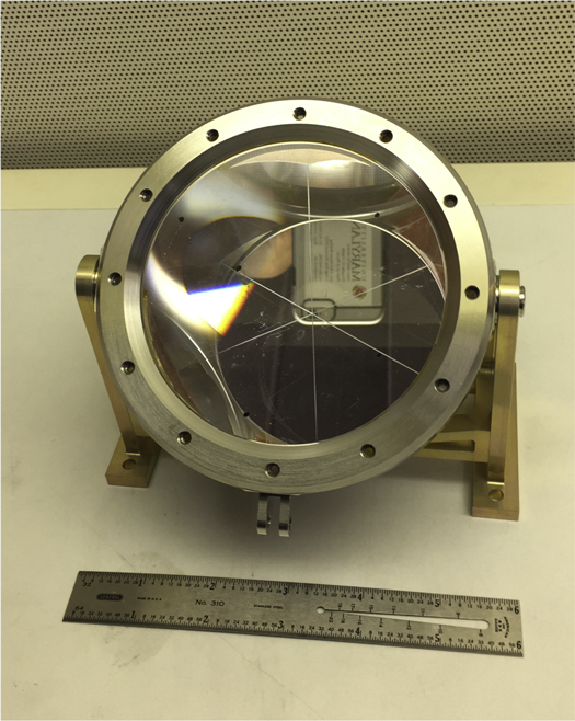
Figure 1. A 10 cm next-generation corner cube in the laboratory.
Download figure:
Standard image High-resolution imageThe arrays for Apollo 14, Apollo 15, and the Lunokhods are shown in Figures 2–4. The Apollo 11 array is similar to the Apollo 14 array. The distant strength of the reflected pulse is proportional to the fourth power of the diameter of a corner cube. The corner cube area contributes a square, and the dimension of the reflected diffraction pattern, which depends on diameter, contributes another square. The size of the diffraction pattern also depends on the laser wavelength. For large corner cubes with narrow diffraction patterns, velocity aberration becomes an issue. The orbital speed of the Moon and the rotational speed of Earth cause velocity aberrations of 0 7–17 (Turyshev et al. 2013). The 3.8 cm Apollo corner cubes have diffraction patterns to the first minimum of ∼35 with green laser beams and twice that with IR that are both larger than the velocity aberration. The 10 cm CCRs will have a central spot with a radius of ∼14 with green beams, tight compared to aberration. In order to correct for velocity aberration, the narrow diffraction pattern of a large CCR can be split into two lobes by introducing a very small deviation in one or more of the three rear 90° dihedral angles (Otsubo et al. 2010, 2011; Currie et al. 2013; Turyshev et al. 2013). However, the combination of TIR and the angle offsets of the rear corner cube faces introduces significant polarization issues. Consequently, the polarization of the transmitted laser transmission at the Lunar Laser Ranging Observatories needs to be considered when designing the angle offsets. The first NGLR corner cube will have a split diffraction pattern from a 05 dihedral angle offset. The decision is pending for the first MoonLIGHT retroreflector.
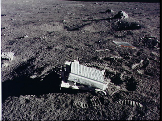
Figure 2. Apollo 14 array of 100 small corner cubes; image from NASA.
Download figure:
Standard image High-resolution imageEach LGN lander on the lunar nearside will carry two NGLRs with their CCRs. One will be attached to the lander leg facing Earth, and a second one will initially be mounted on the instrument deck of the lander. The LGN reflector that is attached to the lander leg will be subject to thermal expansion and contraction of the lander structure, about 0.7 mm vertically for a 300° monthly temperature cycle. The temperature of the footpad will be monitored by the spacecraft for the years of the mission, allowing correction for thermal expansion and contraction. The other NGLR will be deployed directly on the lunar surface to minimize the variation in the range measurements due to the extreme temperature changes from lunar day to lunar night. The two NGLRs will be separated by about 1.5 m, giving ample separation of reflected pulses. When securely in place and pointed toward the mean Earth direction, protective covers will be ejected.
On CLPS missions the optics of the NGLR device will be the same, but the reflector location and deployment will depend on the lander. The CLPS landers are being provided by several different companies with several lander designs. The first NGLR, scheduled to go to Mare Crisium in 2024, will be mounted on the antenna support plate on the top deck of the lander. At <2 kg including the mount, the first NGLR and mount would fit in a box with dimensions 17 × 13 × 12 cm. It is compact and lightweight. The MoonLIGHT reflector is scheduled to go to Reiner gamma in 2024. Both landers will experience thermal expansion and contraction that will need simulations of temperature variations, which depend on reflector location. Both new reflectors will need solution parameters, like the existing arrays do. Records of the lander temperatures would help.
On NASA's Artemis missions, astronauts should place NGLR devices in locations that are remote from activity. Dust deposits on an NGLR CCR are detrimental to its performance, and every effort must be made to isolate the CCR from the activity of the landing site. The CCR should be covered until it is placed at its permanent site.
3. Existing Lunar Laser Ranging Observatories and Retroreflectors
The return laser signal is very weak, and consequently the LLR observatory detectors can time single photons. Normal points are used in our solution software. Three to hundreds of photon arrivals during several minutes are combined into one normal point. The variation in the strength of the signal depends on how steady the atmosphere is, the so-called seeing, and the direction of the laser beam with respect to the CCR normal. Currently, there are four observatories on Earth that have powerful lasers, accurate pointing, accurate timing electronics, and sensitive detectors that range the lunar retroreflectors. These sites are listed in Table 1 as OCA/MeO, France; Apache Point, USA; Matera, Italy; and Wettzell, Germany. Unfortunately, many satellite laser ranging stations do not have the power to range to the Moon. This study includes existing normal point ranges up to the end of 2019. Historical sites that no longer operate are at McDonald Observatory in Texas; Haleakala Observatory on Maui, Hawaii; and the Crimean Observatory in the former USSR.
Table 1. Observations from LLR Stations 1970 March to 2019 December
| Station | Number of Ranges | Time Span |
|---|---|---|
| McDonald 2.7 m, Texas | 3440 | 1970–1985 |
| MLRS, Saddle site, Texas | 275 | 1985–1988 |
| MLRS, Mt. Fowlkes site, Texas | 2870 | 1988–2013 |
| Crimea, Soviet Union | 28 | 1974, 1982–1984 |
| Observatoire de la Côte d'Azur, France (OCA/MeO) | 16089 | 1984–2019 |
| Haleakala Observatory, Hawaii | 694 | 1984–1990 |
| Apache Point Observatory, New Mexico | 2452 | 2006–2016 |
| Matera, Italy | 222 | 2003–2019 |
| Wettzell, Germany | 52 | 2018–2019 |
| Total | 26122 | 1970–2019 |
Download table as: ASCIITypeset image
The five existing sites on the Moon are given in Table 2. The individual Lunokhod corner cubes are larger than the Apollo corner cubes, but there are fewer of them. Due to a silver coating on the three rear faces, the Lunokhod corner cubes experience thermal gradients and thermal distortion when sunlit. The smaller Apollo corner cubes perform better when sunlit, but they still experience thermal distortion when the Sun shines nearly perpendicular to the front face. The performance of both appears to be degraded by dust accumulated over five decades (Murphy et al. 2010, 2014). Reflecting coatings, thermal conduction from the hot housing, and dust on the front face cause front-to-back thermal gradients when sunlit. A thermal gradient causes a gradient in the refractive index that broadens the diffraction pattern and decreases the received signal strength (Murphy et al. 2010; Goodrow & Murphy 2012). Retroreflectors on an orbiting spacecraft are not expected to be affected by dust. They provide a way to compare return signal strength over time with the sites on the lunar surface (Mazarico et al. 2020).
Table 2. Observations Obtained from Retroreflector Arrays, 1970 March to 2019 December
| Lunar Site | Number of Ranges | Percentage | Time Span |
|---|---|---|---|
| Apollo 11, Tranquility | 3104 | 11.9% | 1970–2019 |
| Apollo 14, Fra Mauro | 2934 | 11.2% | 1971–2019 |
| Apollo 15, Hadley | 17326 | 66.3% | 1971–2019 |
| Lunokhod 1, Mare Imbrium | 1193 | 4.6% | 1974, 2010–2019 |
| Lunokhod 2, Le Monnier | 1565 | 6.0% | 1973–2019 |
| Total | 26122 | 100% | 1970–2019 |
Download table as: ASCIITypeset image
4. Simulated Retroreflector Sites
This section gives the locations of the simulated sites using a Moon-centered frame oriented with the principal axes of the lunar moment of inertia tensor. Coordinate X is the reflector coordinate toward the mean Earth direction. Coordinate Z is toward the north pole, and Y completes the triad toward the east. The LGN mission is being designed, and sites have not yet been finalized (for suggested sites see Haviland et al. 2022); only the first CLPS sites for NGLR (Mare Crisium) and MoonLIGHT (Reiner gamma) corner cubes are specified, so the simulated sites in this paper should be considered as suggestive rather than final.
The simulated sites were chosen to be spread wider than the existing arrays since a large geometric extent aids in measuring lunar orientation in space, the physical librations. The three simulated LGN sites are at Mare Crisium (CRS), northwest (NW) near the Aristarchus region, and southwest (SW) in Schickard basin. In addition, a site at the South Pole (SP) was simulated. Non-LGN human and robotic missions to the South Pole are expected. The robotic VIPER mission will drill for ice at Nobile crater, and multiple Artemis crews will visit the South Pole (https://www.nasa.gov). The locations of the four simulated and five existing retroreflectors are listed in Table 3. The Moon-centered radii for the simulated sites are R = 1737 km, the mean radius of the Moon rounded to the nearest kilometer (Smith et al. 2017).
Table 3. Coordinates of Four Simulated and Five Existing Lunar Sites
| Site | Long (deg) | Lat (deg) | X (km) | Y (km) | Z (km) | X /R | Y /R | Z/R | Comment |
|---|---|---|---|---|---|---|---|---|---|
| Crisium | 59 | 17 | 856 | 1424 | 508 | 0.493 | 0.820 | 0.292 | Mare Crisium |
| NW | −50 | 20 | 1049 | −1251 | 594 | 0.604 | −0.720 | 0.342 | Northwest |
| SW | −55 | −45 | 705 | −1006 | −1228 | 0.406 | −0.579 | −0.707 | Southwest |
| S Pole | 0 | −88 | 61 | 0 | −1736 | 0.035 | 0.000 | −0.999 | South Pole |
| Apollo 11 | 23 | 1 | 1592 | 691 | 21 | 0.917 | 0.398 | 0.012 | Tranquillity |
| Apollo 14 | −17 | −4 | 1653 | −521 | −110 | 0.952 | −0.300 | −0.063 | Fra Mauro |
| Apollo 15 | 3 | 26 | 1555 | 98 | 765 | 0.896 | 0.056 | 0.441 | Hadley |
| Lunokhod 1 | −35 | 38 | 1114 | −781 | 1076 | 0.642 | −0.450 | 0.620 | Mare Imbrium |
| Lunokhod 2 | 31 | 26 | 1339 | 802 | 756 | 0.772 | 0.462 | 0.436 | Le Monnier |
Download table as: ASCIITypeset image
The simulations were made before the CLPS sites were announced. The simulated Mare Crisium site is close to the CLPS site at 62°E, 18°N, but the Reiner gamma site at 59°W, 7°N is southwest of the NW site.
5. Conditions of Simulation
Data for 6.0 yr were simulated from 2014 to 2019. The Apollo reflectors become less efficient when heated by the Sun near the local meridian. To impose the monthly observational selection effects for the Apollo sites on the corresponding simulated data, we used existing OCA/MeO station data to the three Apollo reflectors for the times of the simulated data. Apollo 11 times were used for Mare Crisium in the east, Apollo 14 for the Northwest (NW) and Southwest (SW) sites, and Apollo 15, near the zero meridian, for the South Pole (S Pole). Since the larger Apollo 15 reflector acquired more ranges than the other sites, we only used the times for every third observation.
The existing and simulated lunar ranges are analyzed with programs that compare model ranges with real data, calculate partial derivatives with respect to a list of solution parameters, and perform a least-squares adjustment to the solution parameters. The numerically integrated lunar orbit and physical librations follow Park et al. (2021). The range model follows Williams & Boggs (2020). Post-fit residuals are generated and can be examined.
In Table 4 are the coordinates and number of ranges for six simulated cases. In addition to the four individual simulated sites, we analyzed a three-site LGN case and a case with a South Pole plus four LGN sites. A South Pole site is expected from the Artemis or CLPS missions. For comparison, Ref Case uses the real data set without simulated ranges, with solution parameters for libration β = (C–A)/B and γ = (B–A)/C, displacement Love numbers h2 and l2, plus 16 analytical libration terms, equivalence principle cos D, GM(Earth+Moon), reflector coordinates, station coordinates, and other standard solution parameters. The principal moments of inertia have A < B < C. See Williams & Boggs (2020) for a list of solution parameters.
Table 4. Number of Simulated Ranges from 2014 to 2019
| Case | M Crisium | NW | SW | S Pole |
|---|---|---|---|---|
| Ref Case | 0 | 0 | 0 | 0 |
| Crisium | 884 | 0 | 0 | 0 |
| NW | 0 | 778 | 0 | 0 |
| SW | 0 | 0 | 778 | 0 |
| S Pole | 0 | 0 | 0 | 809 |
| Crisium, NW, SW | 884 | 778 | 778 | 0 |
| Crisium, NW, SW, S Pole | 884 | 778 | 778 | 809 |
Download table as: ASCIITypeset image
There are 26,122 normal point ranges to the five original reflector arrays over 50 yr. Over 6.0 yr, from all stations the Apollo 11, 14, and 15 arrays have 1029, 921, and 2837 ranges, respectively. The two Lunokhods (1, 2) have 1042 and 975 ranges, respectively. The total from the five original arrays over 6.0 yr is 6804 ranges. From OCA the three Apollo arrays have 884, 778, and 2432 ranges. Lunokhod 1 and 2 have 961 and 918, respectively, but they are not used as templates. The five-array total is 5973. Each simulated CCR adds 13%–15% to the all-station total over 6 yr.

Figure 3. Apollo 15 array of 300 small corner cubes; image from NASA.
Download figure:
Standard image High-resolution image
Figure 4. A model of the Lunokhod array of 14 corner cubes with a model of the Lunokhod in the background.
Download figure:
Standard image High-resolution imageThe distribution of OCA ranges versus Moon–Sun elongation for the three Apollo arrays during 2014 to 2019 is shown in Figure 5. The bin size is 10°, and lines connect the centers of the bins. New Moon is at 0°, and full Moon is at 180°. There are no ranges at new Moon and fewer than the average at full Moon. All three Apollo arrays peak near first (90°) and third (270°) quarters, but third quarter is higher. The elongation is the difference between the ecliptic longitudes of the Moon and Sun. The Apollo 11 array is in sunlight from elongations 67° to 247°. The Apollo 14 array is in sunlight from 107° to 287°, and the Apollo 15 array is sunlit from 87° to 267°.
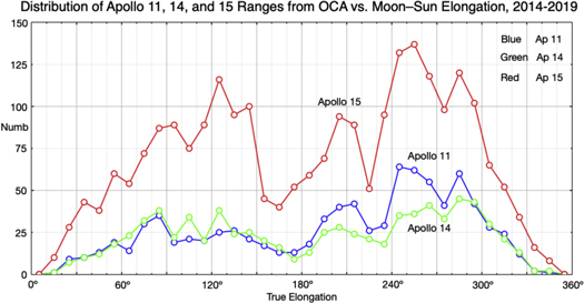
Figure 5. A graph of the distribution of OCA ranges to Apollo 11, 14, and 15 vs. Moon–Sun elongation for 2014 to 2019.
Download figure:
Standard image High-resolution image6. Simulation Results
The lunar orbit is eccentric and perturbed by the Sun. The lunar equator plane has a mean tilt of 6 7 to the orbit plane. These effects cause the apparent position of Earth in the Moon's sky to vary by roughly ±0.1 rad (6°) in both longitude and latitude. These so-called optical librations plus the 1° apparent radius of Earth cause the normal vector to an array's front face to vary by up to 9° in longitude and 8° in latitude from the direction to Earth. See the Appendix for more details. This tilt causes the residuals of single photon arrivals from the CCR arrays to scatter by several centimeters. By contrast, single corner cubes cause no such photon scatter. The optical librations in latitude and longitude have a beat period of 6.0 yr, the argument of perigee period, which we use for the time span of our simulated data.
In a solution, the post-fit rms scatter of normal points is typically larger than the uncertainty that comes with the normal point. Some of the scatter may be in the observation and some in the analysis model (e.g., horizontal gradients in the atmosphere). There also appear to be differences between stations. To improve the weighting of the ranges, we can make two adjustments to the uncertainty of a normal point range observation used in solutions. These are based on an examination of the post-fit residuals. One adjustment is a factor that multiplies the range uncertainty of the normal point given by the LLR observatory. The normal point uncertainty depends on the number of photons in the normal point. The second adjustment is root sum square (rss) noise that is added to the preceding in an rss manner. The rss noise can be due to several things: effects at the station such as calibration and inability to distinguish laser photons reflected from an array from noise photons (noise photons can be laser photons reflected from the lunar surface, sunlight on the surface, sky, or internal instrument noise), unknown geophysical motions, unknown atmospheric effects, and missing effects in the analysis model. For OCA in recent years (2015 March to present), the normal point uncertainty is typically 0.02–0.05 ns (3–7.5 mm), the applied factor is typically 1, and the applied rss noise is 0.07 ns (10.5 mm). Prior to 2015 March 11, the rss noise is 0.08 ns. In fact, the rms residual for OCA ranges to the small arrays from 2014 through 2019 is about 9 mm. The larger Apollo 15 reflector gives 10.5 mm for the rms residual. Comparison of the post-fit residuals with the pre-fit uncertainties shows that the entire 50 yr solution is underweighted by 14%, but this is compensated by multiplying the solution parameter uncertainties by 0.86. Although the solution parameter uncertainties depend on the number of range normal points N and their uncertainties σj
, we have removed the effect of the larger number of ranges from the additional simulated data from our improvements reported below by dividing by ![${\left\{{\rm{\Sigma }}\left[({\rm{O}}-{\rm{C}}{)}_{{\rm{j}}}^{2}/{{\rm{\sigma }}}_{{\rm{j}}}^{2}\right]/({\rm{N}}-{\rm{P}})\right\}}^{1/2}$](https://content.cld.iop.org/journals/2632-3338/3/6/136/revision1/psjac6c25ieqn1.gif) , where (O–C)j
is each observed minus calculated residual, P is the number of solution parameters, and the sum is over the number of real and simulated observations N .
, where (O–C)j
is each observed minus calculated residual, P is the number of solution parameters, and the sum is over the number of real and simulated observations N .
The "reference case" is a solution with existing LLR data from 1970 to 2019. It uses no simulated data.
Six cases add simulated data from 2014 to 2019 to the existing data from 1970 to 2019. There are four assumptions about the uncertainty of each simulated range:
- 1.Range Assumption Set 1: The most conservative assumption weights the simulated data the same as the OCA Apollo data. The factor is 1.0, and the rss value is 0.08 ns prior to 2015 March 11 and 0.07 ns after. Despite the fact that arrays spread the return pulse by several centimeters and that a single corner cube should do better, the weighting is the same as the OCA Apollo ranges.
- 2.Range Assumption Set 2: The factor is 0.5, and the rss value is 0.05 ns (7.5 mm). This is a more realistic uncertainty assumption for the existing station equipment and analysis model.
- 3.Range Assumption Set 3: The normal point factor is 0.1, and the rss value is 0.01 ns (1.5 mm). This would require improvements in both the equipment at the stations and the analysis model.
- 4.Range Assumption Set 4: The normal point factor is 0.01, and the rss value is 0.001 ns (0.15 mm). This would require advanced ranging equipment and advanced modeling. It serves as a goal for future improvements. We note that technical improvements have caused LLR normal point accuracy to improve by two orders of magnitude since the initial months after the Apollo 11 landing, and we anticipate further technical improvements.
Advanced ranging equipment could include a laser with a shorter pulse and faster firing rate. This would increase the number of photons returned from the Moon per minute and improve the calibration. Unmodeled atmospheric delay effects include horizontal gradients in temperature and pressure that could be modeled from global models or local meteorological data or instruments at or near the observatory. Our model (Williams & Boggs 2020) currently includes loading effects at the stations for periodic ocean tides and an approximate correction for atmospheric pressure loading, but there are other loading corrections (Viswanathan 2017; Singh et al. 2021).
For the simulated cases, our predictions of the range residuals are imperfect, and the post-fit rms residuals are a few millimeters. The rms residuals tend to decrease from range uncertainty assumptions 1 to 4 as the simulated data weights increase.
The Moon-centered coordinates of the real and simulated reflectors are solution parameters. Even with present-day range uncertainties, with a month of well-distributed data on a new reflector, the coordinates with respect to the lunar center of mass and principal axes would be determined better than 1 m. The coordinates of existing reflectors with longer data spans are known to ≤0.2 m. Coordinates with uncertainties ≤1 m are useful for tying the Lunar Reconnaissance Orbiter coordinate frame and the LLR frame together (Wagner et al. 2017).
The results of the simulations are shown in Figures 6–11 and tabulated in Tables 5–8. The figures and tables show six parameters of scientific interest selected for illustration, but the solutions had our usual set of parameters, including orbit, station and reflector positions, orientations of Earth and the Moon, and dissipation parameters. Tables 5–8 are ordered by the four range uncertainty assumptions.
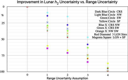
Figure 6. Improvement in vertical displacement Love number h2 with range uncertainty assumption.
Download figure:
Standard image High-resolution imageTable 5. Conservative Range Uncertainty Assumption 1, Solution Parameter Uncertainty/Reference Case Uncertainty in %
| Case | h2 | l2 | β | γ | cos D | GM (E+M) |
|---|---|---|---|---|---|---|
| Ref Case | 100 | 100 | 100 | 100 | 100 | 100 |
| CRS | 86 | 88 | 93 | 84 | 96 | 91 |
| NW | 91 | 93 | 95 | 84 | 96 | 95 |
| SW | 71 | 81 | 92 | 89 | 96 | 86 |
| SP | 40 | 44 | 88 | 99 | 95 | 75 |
| CRS NW | 76 | 83 | 88 | 71 | 91 | 86 |
| CRS SW | 64 | 74 | 86 | 74 | 91 | 80 |
| NW SW | 68 | 77 | 88 | 77 | 91 | 82 |
| CRS NW SW | 63 | 72 | 84 | 68 | 90 | 80 |
| CRS NW SW SP | 36 | 39 | 78 | 68 | 87 | 69 |
Download table as: ASCIITypeset image
Figures 6–11 show the six parameters in sequence. On the figures:
- 1.Results for single reflectors are shown with filled circles: dark blue for Mare Crisium (CRS), light blue for the northwest site (NW), green for the southwest site (SW), and yellow for the South Pole (SP). The single reflector cases show the strength of each reflector for different scientific parameters.
- 2.Results with two LGN reflectors are shown with colored crosses: blue for CRS + NW, green for CRS + SW, and orange for NW + SW. These pairs give the uncertainties for NGLRs on two CLPS missions or if one nearside LGN lander is lost from the mission.
- 3.Simulated results from the nominal three LGN reflectors are shown with red diamonds.
- 4.The South Pole is of particular interest for exploration by robotic landers or human crews. Consequently, CLPS or Artemis missions might place one or more retroreflectors there. Magenta squares present the results for the three LGN sites plus the South Pole site.
Displacement Love number h2 scales the vertical solid-body tide, and l2 scales the horizontal tide. When h2 and l2 are both solution parameters with real range data, they are correlated by 0.92. Increasing one in a solution tends to cause the other to increase. The improvement (in %) in h2 and l2 uncertainty with decreasing range uncertainty is shown in Figures 6 and 7. Because of the high correlation, the patterns are similar, although not identical. The solution with real data, not simulated data (uncertainty assumption 0), has 0% improvement by definition. Even overly conservative range uncertainty assumption 1 gives an improvement of 9%–64% (Table 5), and more realistic uncertainty assumption 2 does better at 11%–71% (Table 6). The cases with three sites and four sites give better results than the single LGN or South Pole sites or the pairs of LGN sites. The single South Pole site with its large negative Z component does much better than the single LGN sites for assumptions 1–3. In addition, the four-site cases with the South Pole (magenta) do much better than the three LGN sites without. The visibility from the South Pole region and the utility of a CCR are discussed by Viswanathan et al. (2020). Potential Love number k2 was held fixed at the value in Williams et al. (2014) that was based on GRAIL mission determinations by Konopliv et al. (2013) and Lemoine et al. (2013).
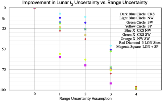
Figure 7. Improvement in horizontal displacement Love number l2 with range uncertainty assumption.
Download figure:
Standard image High-resolution imageTable 6. Likely Existing Range Uncertainty Assumption 2, Solution Parameter Uncertainty/Reference Case Uncertainty in %
| Case | h2 | l2 | β | γ | cos D | GM (E+M) |
|---|---|---|---|---|---|---|
| Ref Case | 100 | 100 | 100 | 100 | 100 | 100 |
| CRS | 72 | 82 | 89 | 74 | 93 | 86 |
| NW | 85 | 89 | 91 | 75 | 93 | 92 |
| SW | 63 | 74 | 87 | 81 | 93 | 80 |
| SP | 33 | 37 | 85 | 99 | 92 | 71 |
| CRS NW | 66 | 74 | 81 | 58 | 86 | 80 |
| CRS SW | 55 | 67 | 78 | 61 | 86 | 74 |
| NW SW | 59 | 67 | 81 | 68 | 87 | 76 |
| CRS NW SW | 53 | 62 | 74 | 54 | 84 | 73 |
| CRS NW SW SP | 29 | 30 | 69 | 54 | 81 | 62 |
Download table as: ASCIITypeset image
The improvements in libration β and γ for different range uncertainty assumptions are shown in Figures 8 and 9. In most cases the simulations with single reflectors show less improvement than the pairs, and the three LGN sites and the LGN sites plus the South Pole site are superior to the single and paired reflector cases. For β, the four-site simulations give noticeably better uncertainties than the three LGN sites. For γ, symbols for the three LGN sites and the LGN sites plus the South Pole site nearly coincide because the South Pole site is nearly insensitive to γ owing to its zero Y coordinate. The yellow circles show the low sensitivity to γ for the South Pole site. By contrast, the South Pole site benefits β owing to its large negative Z coordinate. We expect the longitude-libration-related parameters of the following paragraph to behave like γ and the latitude-libration-related parameters to behave like β. The percentage values will not be identical, but the trends should be similar.
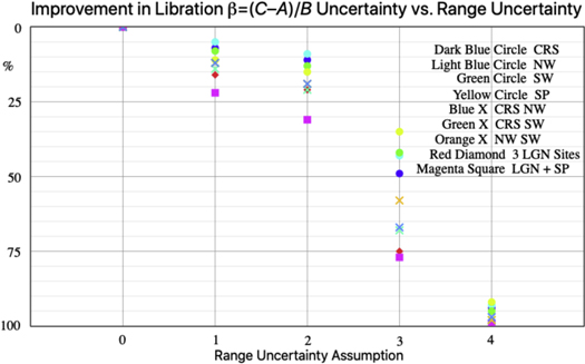
Figure 8. Improvement in libration β with range uncertainty assumption.
Download figure:
Standard image High-resolution image
Figure 9. Improvement in libration γ with range uncertainty assumption.
Download figure:
Standard image High-resolution imageMost of the lunar science parameters cause changes in the orientation of the Moon, the physical librations. In a first approximation, the Moon rotates uniformly, and its equator plane precesses along the ecliptic plane uniformly, completing a circuit in 18.6 yr. However, there are small oscillations about uniform rotation of about 100'' and oscillations of the direction of the pole also of about 100''. See Rambaux & Williams (2011) for details. The physical libration in latitude, the north–south angular motion, is sensitive to libration β = (C–A)/B, energy dissipation at the CMB (Williams et al. 2001), CMB oblateness (Viswanathan et al. 2019), and tidal dissipation k2/Q at 1 month and 6 yr, where k2 is the potential Love number and 1/Q is a measure of energy loss per tidal cycle (Williams & Boggs 2015). The physical libration in longitude, the east–west angular motion, is sensitive to libration γ = (B–A)/C and the tidal dissipation k2/Q at 7 months, 1 yr, and 3 yr. The latitude libration sensitivity depends on the north–south spread of reflectors, the Z coordinate in Table 3. Consequently, latitude-sensitive parameters are most helped by the southwest site and the South Pole site. The longitude libration sensitivity depends on the east–west spread of reflectors, the Y coordinate in Table 3. Thus, longitude-sensitive parameters are helped by the Crisium, Northwest, and Southwest sites.
The listed solution parameters related to physical librations are present in our data analysis software. Future modeling could include dissipation associated with the inner core. The inner core should cause a resonance at an unknown period. We must be alert for any influence of a resonance on forced librations. Forced librations occur at a variety of periods (Rambaux & Williams 2011). Inner core dissipation has been studied by Organowski & Dumberry (2020).
The equivalence principle test depends on the lunar orbit rather than physical librations. The equivalence principle parameter looks for differences between the mass associated with gravitational attraction (gravitational mass) and the mass that resists acceleration (inertial mass). If the ratio of gravitational mass to inertial mass is not the same for Earth and the Moon, then there will be a polarization (offset) of the lunar orbit about Earth along the mean Earth–Sun direction. Such an offset would cause a cos D range variation with a period of 29.53 days (Nordtvedt 1968a, 1968b, 1968c, 1995; Damour & Vokrouhlicky 1996; Williams et al. 2012), where D is the mean geocentric elongation of the Moon from the Sun. A difference in the ratio of gravitational mass to inertial mass for Earth and the Moon might be caused by composition differences (weak equivalence principle) or gravitational self-energy differences (strong equivalence principle). LLR is sensitive to either cause. With a current uncertainty of about 4 mm, no polarization has been detected.
The improvement of the equivalence principle with range uncertainty assumption is shown in Figure 10. The orbit sensitivity causes the four circles to show little scatter for each uncertainty assumption. Similarly, the three crosses for pairs show little scatter among themselves. The three- and four-site cases are best, as expected. For the equivalence principle, improved range accuracy is more important than the geometric spread of reflectors. The equivalence principle uncertainty is affected by the lunar phase selection shown in Figure 5.
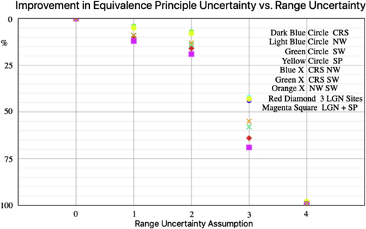
Figure 10. Improvement in equivalence principle cos D coefficient with range uncertainty assumption.
Download figure:
Standard image High-resolution imageOur range model includes thermal expansion of the CCR supporting structure (Williams & Boggs 2020). The vertical thermal expansions for the existing reflectors amount to a few millimeters each lunation (period 29.53 days, but with a different phase and shape than the equivalence principle). The LGN reflectors that are attached to the lander legs will be subject to thermal expansion of the lander structure, but the temperature is to be monitored during the 6 yr of active operation. Those temperature records will be used for thermal expansion corrections during subsequent decades. The LGN reflectors that are anchored in the regolith should show less variation. Thermal expansions of the CLPS-delivered NGLR and MoonLIGHT corner cubes need to be modeled.
Another gravitational physics parameter is geodetic precession, a relativistic rate of rotation of the lunar orbit. We expect that to be more sensitive to range accuracy than the geometric spread of sites, like the equivalence principle.
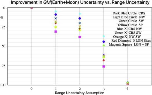
LLR determines the combination GM(Earth+Moon), where G is the gravitational constant and M is the mass. The latter combination and the center-to-center semimajor axis a for the Earth–Moon orbit are connected through Kepler's third law (Δa/a = ΔGM /3GM). Consequently, the uncertainty in GM(Earth+Moon) and the uncertainty in semimajor axis are proportional. Parameters GM(Earth) and GM(Moon)/GM(Earth) are International Astronomical Union astronomical constants (Luzum et al. 2011). LLR determines GM(Earth+Moon) and joint solutions with planetary data determine GM(Moon)/GM(Earth) (Folkner et al. 2014; Park et al. 2021). With existing LLR data, the GM(Earth+Moon) uncertainty is about 0.0004 km3 s−2 and the mean distance is uncertain by about 0.13 m. The improvement in GM(Earth+Moon) with range uncertainty assumption, shown in Figure 11, is a hybrid depending on both orbit (Nordtvedt 1995; Damour & Vokrouhlicky 1996) and a geometrical effect from changes in orientation (Williams et al. 2009). The orbit has a major solar perturbation at half of the synodic period, 14.765 days. The X coordinates of the reflectors project into range with large constant contributions, but they are best determined from smaller half-month terms at 13.606 and 13.777 days (Table 5 of Williams 2018). Consequently, the one- and two-reflector cases show more spread than the equivalence principle but less than the lunar science parameters. As was the case for the other solution parameters, the three LGN sites and the LGN sites plus the South Pole site give the best results. Among the single reflector cases, the South Pole site with nearly zero X gives the strongest improvement of GM(Earth+Moon). Because each site X coordinate projects into range with a factor of –0.9934 (Williams 2018), any error in GM(Earth+Moon) and the mean distance of the Moon will bias all retroreflector X coordinates.
Figure 11. Improvement in GM(Earth+Moon) with range uncertainty assumption.
Download figure:
Standard image High-resolution image
Satellite laser ranging has determined GM(Earth) (Ries et al. 1992; Dunn et al. 1999; Ries 2007). The uncertainty is 0.0008 km3 s−2 (Luzum et al. 2011). GRAIL has determined GM(Moon) well (Konopliv et al. 2013, 2014; Lemoine et al. 2013; Williams et al. 2014), and so have joint solutions of LLR and planetary data (Williams et al. 2014; Folkner et al. 2014; Park et al. 2021).
With existing range data, ranging station positions are determined with few millimeter uncertainties. For the three LLR stations with long spans of data, plate-motion-caused station motions can also be determined. Diurnal and semidiurnal terrestrial tidal dissipations are determined. The LLR analyses are also sensitive to the orientation of Earth in space. LLR analyses can solve for two angles, two rates (precession and obliquity rates), and nutations at four periods (18.6, 9.3, 1, and 0.5 yr).
We note that numerically integrated orbit and physical librations are available for use by lunar missions (Park et al. 2021). Although such use is not a scientific result, the accurate lunar orbit and orientation support missions to the Moon that collect scientific information.
7. Conclusions
The nominal LGN mission to three lunar nearside sites will include two 10 cm diameter solid corner cube retroreflectors at each site. One remains attached to the lander leg, and the other is currently expected to be mounted on the instrument deck of the lander, but it is expected to be placed on the regolith by an arm (Sections 1 and 2). The earlier CLPS missions will also carry the new retroreflectors. An NGLR corner cube (Figure 1) is scheduled to go to Mare Crisium in 2024 March, and a MoonLIGHT corner cube retroreflector is expected to go to Reiner gamma in 2024.
Section 3 tabulates past and present LLR stations on Earth (Table 1) and ranges from the five existing lunar retroreflector arrays (Figure 2–4, Table 2). A wider distribution of reflector sites is desirable for CLPS, LGN, and Artemis sites. Large single corner cubes do not cause the scatter of single photon range measurements that occurs with multiple corner cube retroreflector arrays. Consequently, the range normal point uncertainty comes from noise photons, the initial width of the laser pulse, and the station's electronics.
In Section 4, proposed LGN sites are at Mare Crisium in the northeast, a Northwest (NW) site, and a Southwest (SW) site (Table 3). We simulated these three sites, and, in addition, we simulated a South Pole site.
In Section 5, approximately 800 simulated observations were generated for each of the four simulated sites over 6 yr. The monthly modulations of observations from existing Apollo sites (Figure 5) were used as patterns for simulated ranges from 2014 to 2019. Apollo 14 was used as the pattern for the NW and SW sites, Apollo 11 for Crisium, and Apollo 15 for the South Pole. The exact number of simulated ranges is given in Table 4.
Table 7. Future Range Uncertainty Assumption 3, Solution Parameter Uncertainty/Reference Case Uncertainty in %
| Case | h2 | l2 | β | γ | cos D | GM (E+M) |
|---|---|---|---|---|---|---|
| Ref Case | 100 | 100 | 100 | 100 | 100 | 100 |
| CRS | 42 | 49 | 51 | 40 | 56 | 56 |
| NW | 52 | 54 | 57 | 42 | 58 | 63 |
| SW | 36 | 47 | 58 | 49 | 57 | 50 |
| SP | 21 | 24 | 65 | 96 | 57 | 36 |
| CRS NW | 25 | 27 | 33 | 15 | 42 | 39 |
| CRS SW | 24 | 28 | 30 | 17 | 42 | 37 |
| NW SW | 26 | 26 | 42 | 38 | 45 | 38 |
| CRS NW SW | 20 | 20 | 25 | 14 | 36 | 32 |
| CRS NW SW SP | 15 | 8 | 23 | 14 | 31 | 24 |
Download table as: ASCIITypeset image
In Section 6, nine simulated solutions were generated for each of four range uncertainty assumptions. The nine cases added each of the four simulated sites to the existing data, three cases with LGN pairs, one case with the three LGN sites, and one case with the three LGN sites and the South Pole site. The four range uncertainty assumptions varied from overly conservative (roughly 1 cm) to millimeter ranging, requiring improved equipment and modeling. The percentage improvement in selected solution parameters for the four range uncertainty assumptions is presented in Tables 5–8 and Figures 6–11. The improvements in displacement Love numbers h2 and l2 are particularly noteworthy. Other lunar science parameters should behave in a similar manner to libration β = (C–A)/B and γ = (B–A)/C, where A < B < C are the principal moments of inertia.
Table 8. Future Goal Range Uncertainty Assumption 4, Solution Parameter Uncertainty/Reference Case Uncertainty in %
| Case | h2 | l2 | β | γ | cos D | GM (E+M) |
|---|---|---|---|---|---|---|
| Ref Case | 100 | 100 | 100 | 100 | 100 | 100 |
| CRS | 5 | 3 | 6 | 1 | 2 | 3 |
| NW | 4 | 3 | 7 | 2 | 2 | 3 |
| SW | 6 | 3 | 5 | 2 | 2 | 3 |
| SP | 13 | 4 | 8 | 26 | 2 | 2 |
| CRS NW | 0.7 | 0.6 | 2.5 | 0.3 | 0.8 | 1.1 |
| CRS SW | 1.4 | 0.3 | 1.8 | 0.3 | 0.8 | 1.1 |
| NW SW | 1.1 | 0.7 | 1.8 | 1.0 | 1.1 | 1.1 |
| CRS NW SW | 0.5 | 0.4 | 1.0 | 0.2 | 0.7 | 0.8 |
| CRS NW SW SP | 0.5 | 0.2 | 0.9 | 0.2 | 0.6 | 0.7 |
Download table as: ASCIITypeset image
Placing 10 cm NGLR corner cubes at widely separated CLPS, LGN, and Artemis sites would reduce the uncertainties of a number of lunar science parameters. These include degree-2 displacement Love numbers h2 and l2, tidal dissipation at several frequencies, CMB dissipation, CMB flattening, and moment of inertia combinations β = (C–A)/B and γ = (B–A)/C. Submeter-accuracy coordinates of a new reflector should be available with the first month of well-distributed data. There are also nonlunar science benefits: gravitational physics including the equivalence principle and geodetic precession; Earth science including terrestrial tidal dissipation, ranging station positions and motions, the orientation of Earth in space: the precession and obliquity rates, nutations, and Earth rotation; and astronomical constants with GM(Earth+Moon) for the gravitational constant times the mass of the Earth–Moon system. New retroreflectors on the Moon would benefit several branches of science.
We thank the LLR stations at McDonald Observatory, Texas; Observatoire de la Côte d'Azur, France; Haleakala Observatory, Hawaii; Apache Point Observatory, New Mexico; Matera, Italy; and Wettzell, Germany, which provided the data sets that make LLR analyses possible. LLR data are available from the Crustal Dynamics and International Laser Ranging Service archive at https://cddis.nasa.gov/Data_and_Derived_Products/SLR/Lunar_laser_ranging_data.html. We note that H. Noda of the National Astronomical Observatory of Japan participated in an earlier simulation exercise. Jean-Marie Torre of Observatoire de la Côte d'Azur, France, provided comments on range observations. Investigation of the significant polarization effects that TIR and the angle offsets of the rear corner cube faces introduce was done with C. Wu of the University of Maryland, College Park, MD. Information on the MoonLIGHT landing site was provided by Luca Porcelli and Simone Dell'Agnello of Instituto Nazionale di Fisica Nucleare–Laboratori Nazionale di Frascati, Frascati, Italy (ESA Contract No. 4000129000/19/NL/TFD and ASI Agreement No. 2019-15-HH.0). D. G. Currie acknowledges the support of NASA under Contract No. 80MSFC20C0012 (LSITP). A portion of the research described in this paper was carried out at the Jet Propulsion Laboratory, California Institute of Technology, under a contract with the National Aeronautics and Space Administration (80NM0018D0004). Government sponsorship acknowledged.
Appendix:
In this appendix we consider the effect on the range of an array normal that does not point toward the mean Earth direction. Such tilts can arise from optical and physical librations, the finite angular size of Earth, imperfect alignments of the individual CCRs, and small array pointing errors.
The u vector is a unit vector from Moon center to Earth center with components that use lunar body-fixed principal axes X, Y, Z. Component u1 is the projection on the lunar X-axis, which oscillates about the mean Earth direction. Component u3 is the projection toward the polar Z-axis. Component u2 is the projection toward the Y-axis in the east direction. The u2 and u3 extrema below are for the variable parts and do not include very small constant terms that can arise from third-degree gravitational torques. Uncertainties are in the last digit. The results in Table A1 are based on evaluations of series for the three u components. See Section 6 of Williams (2018) for the largest terms of the three series.
- 1.A minimum u1 of 0.9834 corresponds to a maximum tilt of 1047 when both u2 and u3 are considered together.
- 2.The rms u2 is 0.07940 (4554). A maximum ∣u2
∣ of 0.1421 corresponds to 817 in longitude (larger than a frequently quoted value).
- 3.The rms value of u3 is 0.08243 (4728). A maximum ∣u3
∣ of 0.1196 gives 687 for latitude.
- 4.The mean angular radius of Earth seen from the Moon is 0.0165 rad (095), with minimum and maximum values of 0.0157 rad (090) and 0.0179 rad (102), respectively. The latter was used for the parallax in Table A1. Along with the u2 and u3 components, the angular size of Earth increases the spread of tilts since the ranging stations are not at the center of the rotating Earth. The effect of parallax depends on the station's latitude. We tabulate the maximum value. The effect on the rms scatter is <1%.
Table A1. Array Information and Statistics of Photon Scatter
| Array | Ap 11 | Ap 14 | Ap 15 | Lk 1 | Lk 2 |
|---|---|---|---|---|---|
| External array size (cm) | 46 × 46 | 46 × 46 | 104 × 55 | 44 × 19 | 44 × 19 |
| Number of CCRs, rows × columns | 10 × 10 | 10 × 10 | 25 × 12 | 7 × 2 | 7 × 2 |
| CCR arrangement | square | square | hexagonal | alternating triangles | alternating triangles |
| rms scatter in cm | 1.5 | 1.5 | 2.6 | 0.9 | 0.9 |
| Max scatter in cm | 5.4 | 5.4 | 10.2 | 3.1 | 3.1 |
| Max scatter + parallax in cm | 5.9 | 5.9 | 11.1 | 3.4 | 3.4 |
Download table as: ASCIITypeset image
In Table A1 we present the external array size, the number of rows and columns of CCRs, the arrangement of CCRs (see Figures 2–4), the rms photon scatter in range, the absolute value of the maximum range deviation, and the maximum including parallax. The Apollo CCRs are recessed with a hole that is a few millimeters larger than the 3.8 cm CCRs. The Lunokhod arrangement of alternately oriented triangles seen in Figure 4 has the centers of the triangles arranged in two rows on each side of the midline. Consequently, the effective pattern is 3, 4, 0, 4, and 3 triangle centers.
Presuming that the array normal points toward the mean Earth direction, the tilt θ of the array horizontal with respect to the equator plane is

where Y and Z are the Moon-referenced site components given in Table 3. The displacement of a photon from the mean in range Δρ is

where x is the horizontal coordinate of a corner cube and y is its orthogonal coordinate, both measured from the center. For the maximum value of ΔρCORNER of a CCR at array corner coordinates ± h/2 and ± v/2, where h is the horizontal (CCR center-to-center) size of the array and v is its orthogonal dimension,
Calculate both and pick the larger one. To include maximum parallax, multiply the corner deviation by 1.096. The rms scatter is calculated from the sum square

where the summation is over the individual CCR coordinates xi
and yi
and 〈〉 denotes an average over time so that  and
and  are the two rms values squared. To get the rms scatter, divide the sum squared
  by the number of corner cubes and take the square root. As a caveat, the rms calculation does not account for array efficiency versus angle, so in reality the strength of the signal will affect detectability and the observed rms value. The extreme values will not be affected. The foregoing expressions are used to calculate the last three lines in Table A1.
The Apollo arrays had bubble levels to establish the horizontal and devices for orienting the azimuthal direction by astronauts so that the array normal pointed toward the mean Earth direction (Alley et al. 1969; Faller et al. 1971, 1972). The Lunokhod arrays were pointed toward Earth when stopping for each night. Consequently, Lunokhod 1 should be properly oriented since it failed to start one lunar morning. Lunokhod 2 moved in the morning before it died, so there is uncertainty about its orientation.
Currently, the ranging stations reduce the libration-caused normal point uncertainty from corner cube retroreflector arrays by collecting many photons. A single NGLR or MoonLIGHT corner cube would eliminate this uncertainty, improving the precision of the normal point. The normal point scatter would come from noise photons, initial pulse width, and the ranging electronics at the station. Noise photons come from the laser pulse bounce off of the lunar surface, sunlight on the surface, and sky. Consequently, improvements to the equipment would be beneficial.