


Abstract
We present the discovery of a spatially unresolved source of submillimeter continuum emission (λ = 855 μm) associated with a young planet, PDS 70 c, recently detected in Hα emission around the 5 Myr old T Tauri star PDS 70. We interpret the emission as originating from a dusty circumplanetary disk with a dust mass between 2 × 10⁻³ M⊕ and 4.2 × 10⁻³ M⊕. Assuming a standard gas-to-dust ratio of 100, the ratio between the total mass of the circumplanetary disk and the mass of the central planet would be between 10−4 and 10−5. Furthermore, we report the discovery of another compact continuum source located 0 074 ± 0013 southwest of a second known planet in this system, PDS 70 b, that was previously detected in near-infrared images. We speculate that the latter source might trace dust orbiting in proximity of the planet, but more sensitive observations are required to unveil its nature.
1. Introduction
According to current theories, as the mass of a forming planet increases above ∼10 Earth masses (M⊕), the planet is expected to open a partially depleted gap in the circumstellar disk (Crida et al. 2006). Material flowing through the gap that enters the region where the gravity of the planet dominates over that of the host star (i.e., the planet Hill sphere) is trapped in orbit, forming a rotating circumplanetary disk (CPD; Ward & Canup 2010). In analogy with the star formation process, circumplanetary material is expected to lose angular momentum due to turbulence and viscosity, and accrete onto the planet at a rate between 10−4 and 10−8 Jupiter masses (MJ) per year for a period of time comparable with the lifetime of the circumstellar disk, i.e., a few Myr (Lubow & Martin 2012). Consequently, for a planet like Jupiter, more than 50% of its mass might have passed through a CPD.
In addition to regulating the final mass of giant planets, CPDs are the birthplace of satellites such as the main moons of Jupiter and Saturn. The density, temperature, and viscosity of a CPD is expected to control the formation, composition, and architecture of the system of satellites (Canup & Ward 2009). However, the limited number of moon systems in the Solar system and the lack of exomoon discoveries, limit our understanding of how their formation occurs. The recent realization that Europa might harbor conditions suitable for life under its icy surface (Pappalardo et al. 2013) stresses the importance of studying how moons of giant planets form.
Gas accretion through CPD and the irradiation from both the host star and the central planet might warm up gas and dust, making the CPD bright at infrared (IR) and (sub)millimeter wavelengths (Isella et al. 2014; Szulágyi et al. 2018; Zhu et al. 2018). Furthermore, the gas falling onto the planet and/or its CPD might reach temperatures of thousands of Kelvin and emit hydrogen recombination lines (e.g., Hα) and ultraviolet (UV) continuum emission (Zhu 2015; Marleau et al. 2017; Aoyama et al. 2018).
To date, a few giant planet candidates still embedded in their parental circumstellar disks have been claimed (e.g., Kraus & Ireland 2012; Sallum et al. 2015; Reggiani et al. 2018), but most still lack confirmation. The most outstanding case is the PDS 70 system, which comprises a ∼5 Myr old low-mass () T Tauri star at a distance of 113.4 pc (Müller et al. 2018, and references therein) surrounded by a disk with a large inner cavity. A planetary-mass companion was detected within the cavity at multiple near-infrared (NIR) wavelengths (1.0 μm < λ < 3.8 μm) and at different epochs between 2012 and 2018 (Keppler et al. 2018; Müller et al. 2018). This companion, PDS 70 b, was also detected in the Hα line (λ = 0.656 μm; Wagner et al. 2018), suggesting that it is accreting gas. Recently, a second companion candidate, PDS 70 c, was discovered in Very Large Telescope/Multi Unit Spectroscopic Explorer (VLT/MUSE) observations in the Hα line (8σ detection; Haffert et al. 2019). The two planets orbit at about 23 and 35 au from the central star and have masses estimated to range between 4 and 12 MJ, while the observed Hα line indicates a mass accretion rate of about 10−8 MJ yr−1. PDS 70 was recently observed at the wavelength of 855 μm with the Atacama Large Millimeter/submillimter Array (ALMA) by Keppler et al. (2019), who found that most of the circumstellar dust is confined in a large dust ring characterized by a radius of 74 au. Furthermore, ALMA observations reveal the presence of an inner disk with a radius smaller than 10 au, and a faint spur of dust extending from the outer ring toward the inner disk. Interestingly, the latter feature was observed at the position of PDS 70 c, though the existence of this planet was not known at the time that the ALMA data were published. Hydrodynamical modeling of the gas kinematics presented in this Letter suggest the presence of an additional low-mass companion beyond the orbit of PDS 70 b to account for the large gap extent. No emission was reported at the location of PDS 70 b, implying an upper limit of about 0.01 M⊕ for the dust component of a possible CPD.

In Section 2 of this Letter, we show that an improved calibration of existing ALMA observations of PDS 70 reveals that the dust spur identified by Keppler et al. (2019) is a compact source of emission spatially separated from the dust ring and located at the position of PDS 70 c. Furthermore, we report the detection of a continuum emission close, but not coincident, to the position of PDS 70 b. We label these two sources PDS 70 csmm and PDS 70 bsmm, respectively. In Section 3, we argue that PDS 70 csmm might probe dust emission from a CPD and, by comparison with simple CPD models, we estimate a dust mass between 2 × 10⁻³ and 4.2 × 10⁻³ M⊕. In Section 4 we discuss the main caveat affecting this estimate and speculate about the nature of PDS 70 bsmm. We conclude by summarizing our findings in Section 5.
2. Observations
The results presented in this Letter are based on an improved calibration of the ALMA band 7 (λ = 855 μm) observations of PDS 70 published in Keppler et al. (2019) and Long et al. (2018). The source was initially observed in 2016 August (project ID: 2015.1.00888.S) using an array configuration characterized by baselines extending between 15 m and 1.5 km, and it was observed again between the 2017 December 2 and 6, (project ID: 2017.A.00006.S) using a more extended array configuration with baselines between 15 m and 6.9 km. The combination of the two sets of observations probes angular scales between about 0025 and 12'', corresponding to spatial scales between 2.8 and 1360 au at the distance of PDS 70. The ALMA correlator was configured to observe both continuum and molecular line emission, but here we focus on the continuum emission. We refer to Keppler et al. (2019) for a discussion of the observed CO emission.
Observations taken at the two different epochs were calibrated using the ALMA pipeline and imaged by us using the procedure described in Andrews et al. (2018). One key step of the imaging process is the self-calibration of the continuum visibilities, which allows to correct short-timescale phase fluctuations and improve the imperfect long-timescale phase calibration derived from observations of a nearby point source. Differently from Keppler et al. (2019), we find that self-calibration does improve the continuum image and results in a 40% increase in the peak signal-to-noise ratio (S/N). Furthermore, in imaging the ALMA data we discovered that the observations acquired in 2016 were calibrated by the ALMA pipeline using an incorrect gain calibrator flux, which resulted in overestimating the flux density of the PDS 70 disk by about 25%. The self-calibration and imaging was performed in CASA 5.1.1 following the procedure presented in Appendix A.
We imaged both single-epoch and combined ALMA data using Briggs weighting with robust parameters varying from 2 (which mimics natural weighting) to −0.3 (lower values result in significantly higher noise). In Figure 1, we show images of the PDS 70 disk obtained from the combined data using robust = 2 and 0.3. These maps most clearly reveal the presence of faint substructures in continuum emission. However, we stress that our results do not depend on the assumed weighting scheme, and, in particular, that the compact sources of continuum emission discussed below were identified with the adopted range of weightings in both the combined and 2017 data alone.

Figure 1. ALMA images of the 855 μm continuum emission recorded toward the inner regions of the PDS 70 circumstellar disk. The image on the left was obtained adopting a robust parameter of 2 and has an angular resolution (FWHM of the synthesized beam) of 0093 × 0074 indicated by the black ellipse on the bottom left. The image in the middle panel was created adopting a robust parameter of 0.3 and has an angular resolution of 0067 × 0050. White contours are drown at 3 and 5 times the rms noise level. See the text for the details. The labels PDS 70 bsmm and PDS 70 csmm indicate the compact sources of continuum emission discovered inside the dust cavity. The image on the right shows an overlay between the VLT/Spectro-Polarimetric High-contrast Exoplanet REsearch (SPHERE) NIR image published in Müller et al. (2018), and the ALMA low-intensity red contours from the image with robust = 2.0.
Download figure:
Standard image High-resolution imageThe map generated using robust = 2 has an rms noise of 18 μJy beam−1 and achieves an angular resolution (FWHM of the synthesized beam) of 0093 × 0074. In the following, we will refer to this image as the natural image. Conversely, the map generated with robust = 0.3 (i.e., the robust image) has a slightly higher noise (rms = 19 μJy beam−1) but achieves better angular resolution (FWHM = 0067 × 0050). Overall, the natural and robust images show the same disk morphology, which agrees with the results presented in Keppler et al. (2019).
The main feature is a bright elliptical ring with semimajor axis of about 065, semiminor axis of 04, position angle of the semimajor axis of about 158° (as measured from the north toward the east), and a flux density of 177 mJy. Assuming that the dust ring is intrinsically circular, the measured aspect ratio implies a disk inclination of 52°. The continuum intensity varies along the ring. In the natural image, the intensity reaches a maximum of 2.5 mJy beam−1 at a position angle of 325° and a minimum of 1.7 mJy beam−1 at a position angle of 94°. A similar relative variation is measured in the robust image. A second feature of the continuum emission is a central component characterized by a flux density of 0.7 mJy. A 2D elliptical Gaussian fitting of the emission returns a beam-deconvolved semimajor axis of 010 ± 001, a semiminor axis of 008 ± 001, and a position angle of 177° ± 15°. The inclination and position angle of the central component appear to be consistent with those of the dust ring. These two features were discussed in details in Keppler et al. (2019) and will not be further analyzed here.
In the rest of this Letter we focus on the discussion of two additional sources of continuum emission detected inside the dust cavity. The first, labeled PDS 70 bsmm, has a peak intensity of 100 ± 18 μJy beam−1 (S/N ∼ 5.5) and 73 ± 19 μJy beam−1 (S/N ∼ 3.8) in the natural and robust images, respectively. A 2D Gaussian fit of PDS 70 bsmm indicates that the source is much smaller than the synthesized beam, suggesting a beam-deconvolved physical diameter ≲4 au. The second source, labeled PDS 70 csmm, is better seen in the robust image where it is spatially separated from the dust ring (see also Appendix B). PDS 70 csmm has a peak intensity of 106 ± 19 μJy beam−1 (S/N ∼ 5.6) and its morphology is also consistent with a point source.
The astrometric positions of PDS 70 bsmm and PDS 70 csmm are calculated with respect to the center of the disk, which is defined as the center of the innermost component of continuum emission as well as the center of rotation as inferred from the 12CO J = 3–2 line emission. These measurements, which are discussed in Appendix C, lead to consistent results (Table 2). PDS 70 bsmm and PDS 70 csmm are both separated by 021 from the center of the disk and are located at position angles of about 165° and 283°, respectively.
3. Data Analysis
3.1. Comparing Optical, NIR, and Sub-mm Astrometry
Figure 2 compares the relative astrometric positions of PDS 70 bsmm and PDS 70 csmm to those of PDS 70 b and PDS 70 c measured in 2016 and 2018 (see Table 2). It must be noted that the position of the ALMA sources are relative to the center of the 855 μm continuum emission and CO kinematics as discussed in Appendix C. Conversely, the optical and NIR astrometry is measured relative to the stellar position. In order to compare these measurements, we must therefore assume that the star is at the center of the disk.

Figure 2. Measured astrometry for PDS 70 b and c with 3σ error bars (see Table 2). The labels "smm cont" and "smm CO" refer to the position of the ALMA continuum sources relative to the center of the continuum emission and the center of the disk rotation as measured from the CO line emission, respectively.
Download figure:
Standard image High-resolution imageThe position of PDS 70 csmm is in agreement with the optical and NIR position of PDS 70 c (see also Figures 1 and 8). At the estimated orbital radius 34.5 au, the orbital period of PDS 70 c should be 230 yr, implying an angular yearly motion of about 0008 in the clockwise direction, assuming a circular and coplanar orbit. This is consistent with the shift observed between 2016 and 2018. PDS 70 bsmm appears to be located southwest of PDS 70 b at an angular distance of 0074 ±0013, as calculated by comparing the ALMA position with the closest NIR epoch (2018 February 24 from Müller et al. 2018). This offset, which is also visible in the overlay between ALMA and VLT/SPHERE observations shown in Figure 1, suggests that PDS 70 bsmm and PDS 70 b might have different physical origins (see Section 4). Although the present analysis has a caveat that the ALMA reference position might not correspond to the position of the central star, a substantial offset would be required to reconcile the difference and introducing such an offset would lead to a disagreement in positions of PDS 70 c and PDS 70 csmm. Future ALMA observations capable of imaging the innermost disk regions in greater details might better pinpoint the position of the central star relative to the circumstellar material.
3.2. Estimating the CPD Dust Mass
The agreement between the position of PDS 70 csmm and its optical/NIR counterpart, and the fact that the sub-mm emission is spatially unresolved at the sensitivity and resolution of current observations, strongly suggest that PDS 70 cmm traces warm dust emission from a CPD. This hypothesis is supported by the detection of Hα line emission attributed to accreting gas (Figure 8, Haffert et al. 2019). The planet itself would emit at submillimeter wavelengths; however, we calculate that its 855 μm flux should be less than 0.1 μJy (assuming planet effective temperatures and radii as in Müller et al. 2018).
The spatially integrated flux measured by ALMA can be used to estimate the mass of the CPD. Following Isella et al. (2014), we assume that CPDs are vertically isothermal with a radial temperature profile (TCPD) controlled by the sum of internal viscous heating (Tacc) and external irradiation from both the central planet (Tirr,p) and the host star (), so that


We assume a stellar luminosity L⋆ = 0.36L⊙ (Müller et al. 2018), while the physical parameters for PDS 70 c (and b) are listed in Table 1. The luminosity of PDS 70 c is not known, but because the masses and ages of PDS 70 b and PDS 70 c are thought to be similar, we assume that they might also have similar luminosities.
Table 1. Adopted Parameters for PDS70 b and PDS70 c
| Name | Mp/MJ | Lp/L⊙ | a/au | |
|---|---|---|---|---|
| (1) | (2) | (3) | (4) | (5) |
| PDS70 b | 5–9 | 1.6 × 10⁻⁴ | 20.6 ± 1.2 | 2 × 10⁻⁸ |
| PDS70 c | 4–12 | 1.6 × 10⁻⁴ | 34.5 ± 2.0 | 1 × 10⁻⁸ |

Note. Data from Wagner et al. (2018), Keppler et al. (2018), and Haffert et al. (2019).
Download table as: ASCIITypeset image
The stellar irradiation at the position of PDS 70 c might depend on the geometry of the inner part of the circumstellar disk, as this might occult the planets from direct stellar radiation, and on the amount of stellar light scattered by the circumstellar dust ring toward the planet itself (see, e.g., Turner et al. 2012; Isella & Turner 2018). In first approximation, a lower limit of might correspond to the midplane temperature of an optically thick circumstellar disk, where all the stellar light is absorbed in the disk surface and re-processed toward the disk midplane (Chiang & Goldreich 1997). At the orbital radius of PDS 70 c, this approximation gives Tirr,⋆ =20 K. Conversely, an upper limit for Tirr,⋆ corresponds to the equilibrium temperature of a blackbody embedded in the unattenuated stellar radiation, which gives Tirr,⋆ = 80 K.

The temperature due to the irradiation from the planet scales with the distance r as

where μ = 0.1 is the assumed aspect ratio of the CPD, Lp is the planet luminosity, and σ is the Stefan–Boltzmann constant. Assuming Lp = 1.6 × 10⁻⁴ L⊙ and Tirr,⋆ = 80 K, we find that Tirr,p > Tirr,⋆ at r < 0.1 au. Instead, if we assume Tirr,⋆ = 20 K, Tirr,p > Tirr,⋆ for r < 1.0 au.
Finally, the temperature due to viscous heating is

For the parameters of PDS 70 c, Tacc varies between one-third and one-seventh of Tirr,p, suggesting that viscous heating might have a very marginal role.
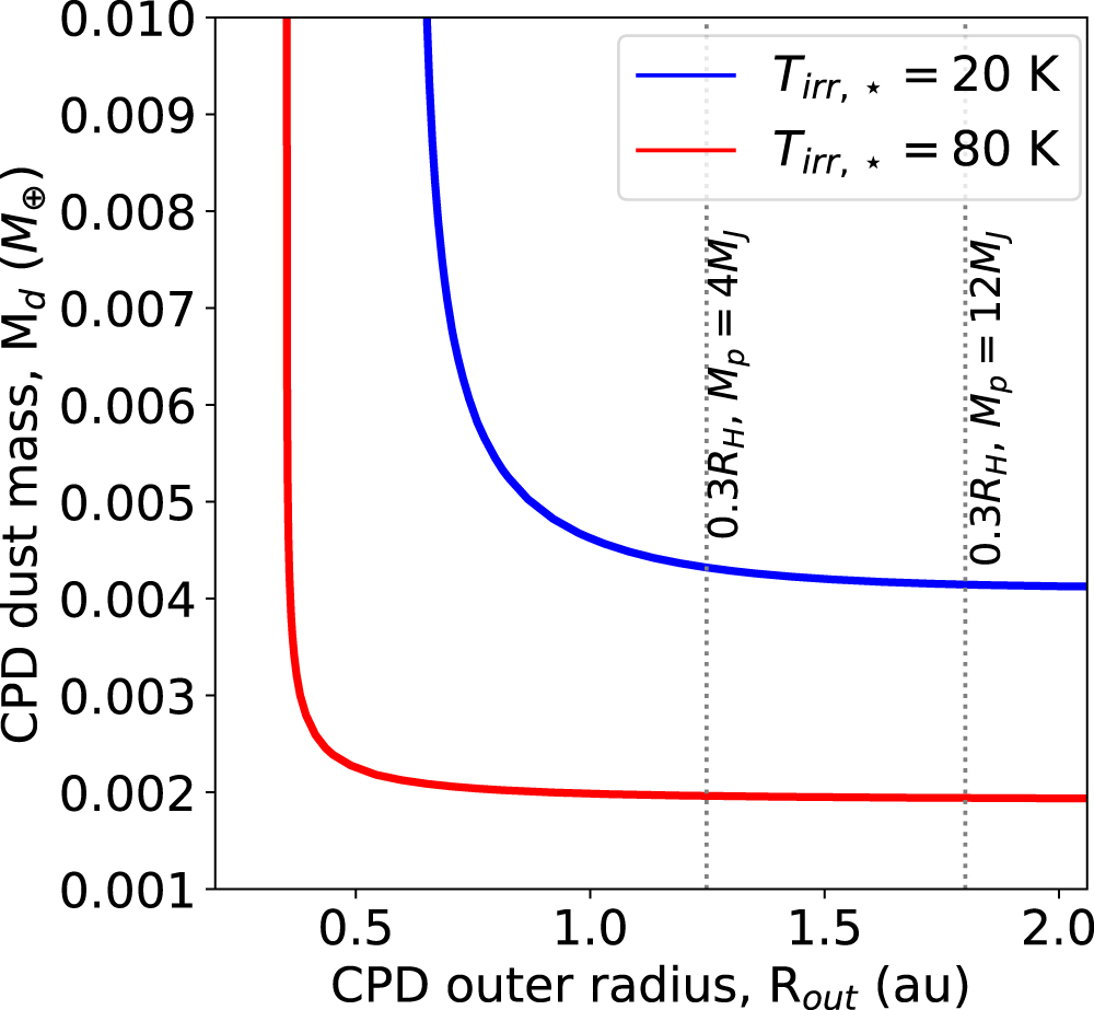
From the CPD temperature derived using Equations (1)–(3), and the lower and upper limits of Tirr,⋆, we calculate the expected CPD continuum emission at 855 μm using Equation (4) in Isella et al. (2014). To this end, we assume a CPD inclination equal to that of the circumstellar disk (i = 51 7, Keppler et al. 2019), and a dust surface density proportional to r−1. Isella et al. (2014) showed that the slope of the surface density profile has little effect on the total disk flux. We assume an inner disk radius equal to the planet radius, which is estimated to be about 3 Jupiter radii based on the planet temperature and luminosity, and a dust opacity of 3.5 cm2 g−1 (Keppler et al. 2019). We calculate continuum fluxes for a grid of models characterized by dust masses (Md) between 10−3 M⊕ and 10−1 M⊕, and disk outer radii between 0.3 au and 3 au. Theoretical models predict that CPDs should be truncated between one-third and one-half of the planet Hill radius () (Quillen & Trilling 1998). For the estimated mass range of PDS 70 c, the CPD outer radius might therefore be between 1.4 au and 3 au.
![${R}_{{\rm{H}}}=a\sqrt[3]{{M}_{p}/3{M}_{\star }}$](https://content.cld.iop.org/journals/2041-8205/879/2/L25/revision1/apjlab2a12ieqn5.gif)
CPD models that match the 855 μm continuum flux of PDS 70 cmm (106 μJy) are shown in Figure 3. As expected, the inferred dust mass depends on the disk temperature so that more dust is needed to explain the observed flux if the disk is colder. If Rout ≳ 1 au, the dust mass is almost independent on the disk outer radius, and it reaches values of 2 × 10⁻³ M⊕ and 4.2 × 10⁻³ M⊕ in the high and low temperature models, respectively. This behavior is due to the fact that, in this regime, CPDs are mostly optically thin at 855 μm. As a consequence, the dust emission scales linearly with the dust mass but is independent on the emitting area. For example, the dust surface density of the CPD model characterized by Tirr,⋆ = 20 K, Md = 4.3 × 10⁻³ M⊕, and Rout = 1.25 au (Rout = 0.3RH for Mp = 4 MJ), is , which, for the adopted dust opacity, corresponds to an optical depth below 1 for r > 0.05 au.


Figure 3. Solid lines show the dust mass and outer radius of a CPD characterized by 855 μm continuum fluxes equal to that measured toward PDS 70 c (106 μJy). Blue and red colors correspond to CPD models where the stellar irradiation alone would result in a CPD temperature of 20 K and 80 K, respectively. Vertical dashed lines are drawn at 0.3 times the Hill radius for planet masses of 4 MJ and 12 MJ.
Download figure:
Standard image High-resolution imageIf the CPD outer radius is smaller than 1 au, the dust mass required to explain the observed emission leads to higher, more optically thick surface densities. In the limit of τ ≫ 1, the disk flux scales linearly with the emitting area (i.e., F ∝ Rout2), and isoflux curves turn from horizontal to vertical. The transition between optically thin and thick regime, as well as the minimum outer radius compatible with the observations, depend on the disk temperature. We find that the CPD of PDS 70 c might have an outer radius as small as 0.35 au (0.08RH for Mp = 4 MJ) if T⋆,irr = 80 K, and about 0.6 au (0.15RH) if T⋆,irr = 20 K.
The same procedure can be applied to estimate the mass and outer radius of a CPD around PDS 70 b, although astrometric measurements might suggest that the observed submillimeter emission have a different origin. In this case, the measured 855 μm flux would correspond to dust masses between 1.8 × 10⁻³ M⊕ and 3.2 × 10⁻³ M⊕ for optically thin disks larger than ∼0.7 au, or a minimum outer radius of 0.2 au if the emission is optically thick.
4. Discussion
Inferring the existence and measuring the properties of CPDs is important to constrain both planet and moon formation models. The detection of a compact source of sub-mm emission at the position of PDS 70 c confirms the hypothesis that the Hα line emission recently detected by Haffert et al. (2019) probes gas accreting onto a young planet from a CPD. The constraints set on the dust mass suggest that the CPD might have a relatively low mass compared to that of the planet. Using a standard gas-to-dust ratio of 100, the total mass of the CPD would be 10−4–10−5 times the mass of the planet, unless the CPD is so small (Rout ≲ 0.1RH) to become optically thick. For comparison, the minimum mass of solids required to form Jupiter's Galilean moons is 6.5 × 10⁻² M⊕. This corresponds to a total gas mass of about 2% of the mass of Jupiter. Theoretical models for the formation and evolution of giant planets (e.g., Ward & Canup 2010) predict low CPD/planet mass ratios only toward the end of the planet accretion phase, and after the planet has accreted most of its mass.
In discussing the comparison between theory and observations, the caveats related to the measurement of the CPD mass cannot be neglected. Similarly to the case of circumstellar disks, the main source of uncertainty in calculating dust masses from submillimeter fluxes resides in the limited knowledge of the dust opacity. The assumed value of 3.5 cm2 g−1 is appropriate for dust grains with chemical composition typical of those observed in the interstellar medium and a Mathis, Rumpl, & Nordsieck (MRN) grain size distribution (n ∝ a−3.5) with a maximum grain size extending a few millimeters (Birnstiel et al. 2018). However, while millimeter-sized grains have been observed in circumstellar disks, it is unclear whether they might exist in a CPD. For example, in the case of PDS 70, it is thought that the observed circumstellar dust ring might trap most of the large dust grains so that the material flowing from the circumstellar to the circumplanetary disk might be depleted in solids, and, in particular, in mm-size grains. Furthermore, mm-size grains in the CPD are expected to quickly drift inward as a result of the gas drag (Zhu et al. 2018). As counter arguments, small solids in the CPD might collide and grow in size to form larger particles (Shibaike et al. 2017), and local maxima in the gas density could slow down the inward radial drift of dust particles, as observed in several circumstellar disks (see, e.g., Dullemond et al. 2018). However, if for any reason the maximum grain size in the CPD is smaller than about than 100 μm, the true dust opacity might be a factor of several lower than the adopted value, and, consequently, the dust mass might be a factor of several larger. Future multi-wavelength ALMA observations that measure the spectral slope of the CPD continuum emission will help breaking the degeneracy related to the grain size distribution. Furthermore, observations of both optically thin and thick molecular lines could be used to constrain the gas density and temperature, allowing for a more quantitative comparison between observations and models.
The last item of discussion concerns the nature of PDS 70 bsmm. Its proximity to PDS 70 b suggests that the observed continuum emission might be somehow related to the planet. Due to the uncertainties on the position of the host star in the ALMA images, we cannot exclude that the submillimeter continuum arises for circumplanetary dust. This was already discussed in Section 3. One possibility to explain the offset might be that PDS 70 bsmm traces dust particles trapped at the Lagrangian point L5, about 60° behind PDS 70 b in azimuth along its orbit. Numerical simulations predict that if the disk viscosity is low (α < 10−4) solid particles might be trapped at this Lagrangian point for more than 1000 orbits (Lyra et al. 2009; Ricci et al. 2018; Zhang et al. 2018). In the case of PDS 70 b, this would imply particle lifetimes larger than about 105 yr. Such a possibility, however, prefers an inclined orbit (∼20°) with respect to the disk midplane, assuming that the direction of the ascending node aligns with the circumstellar disk's position angle and that optical/NIR and sub-mm emissions arise from the midplane. Future long-term follow-up observations will better constrain the orbital parameters of PDS 70 b and help examine this possibility. As an alternative, we speculate it might be possible that optical/NIR traces emission from a jet similar to the ones from accreting protostars (e.g., Hartigan et al. 2011). However, in order to explain the redshifted Hα emission reported by Haffert et al. (2019), the magnetic dipole of the planet must by substantially misaligned (>40°) with respect to the circumstellar disk. In either case, deep follow-up observations in both optical/NIR and sub-mm wavelengths are highly desired to elucidate the nature of this source.
5. Conclusions
We presented the detection of 855 μm continuum emission at the position of the planet PDS 70 c that we attribute to dust emission from a CPD. This result supports the hypothesis that this planet is still in its accretion phase (Haffert et al. 2019). We have shown that the sub-mm flux measured at the position of PDS 70 c constrains the total dust mass to be between 2 × 10⁻³ M⊕ and 4.2 × 10⁻³ M⊕, if the CPD outer radius is larger than about 0.3RH as predicted by theory. Taken at face value, our results indicate that the mass of PDS 70 c CPD might be very low compared to that of the planet (Md/Mp ∼ 10−4–10−5). Such low mass ratio, and the low mass accretion rate measured by Haffert et al. (2019), suggest that the PDS 70 c might have already accreted most of its final mass. We reported the detection of another compact source of continuum emission (PDS 70 bsmm) located about 0074 away from PDS 70 b, the other known planet of this system, for which we do not currently have any robust interpretation.
The discovery of a CPD at sub-mm wavelengths paves the way for the characterizations of the environment surrounding giant planets in the act of forming, and for the study of the interaction between the circumstellar and the circumplanetary disk. Furthermore, the presented ALMA observations demonstrate the capability to measuring orbital parameters of young planets at (sub)-millimeter wavelengths. We argue that optical, NIR, and (sub)millimeter observations are highly complementary because they probe diverse aspects of planet accretion processes and are affected by different systematic errors. The relative astrometric accuracy of ALMA observations is comparable to that achieved in the optical/NIR and is not contaminated by direct or scattered stellar light, which might mislead the interpretation of short wavelength observations. However, the offset between PDS 70 b and PDS 70 bsmm shows that ALMA observations alone might not be sufficient to identify planets in the act of forming. As ALMA and existing optical telescopes are reaching their full imaging capabilities, forthcoming observations of nearby circumstellar disks characterized by cavities and gaps like those observed in PDS 70 might reveal more newborn planets interacting with their natal disk. Such observations are fundamental to investigating the processes responsible for the formation of planetary systems.
We acknowledge A. Muller, S. Haffert, J. de Boer, and A. Vigan for kindly sharing their VLT (SPHERE and MUSE) reductions. We thank the anonymous referee for helping improving the manuscript. A.I. acknowledges support from the National Science Foundation under grant No. AST-1715719. M.B. acknowledges funding from ANR of France under contract number ANR-16-CE31-0013 (Planet Forming Disks). R.T. acknowledges support from NSF grants AST-1514670 and NASA NNX16AB48G. J.B. acknowledges support from NASA grant NNX17AE31G. L.P. acknowledges support from CONICYT project Basal AFB-170002 and from FONDECYT Iniciación project #11181068. M.K. acknowledges funding from the European Unions Horizon 2020 research and innovation program under grant agreement No. 730562 (RadioNet). S.F. acknowledges an ESO Fellowship.
Facility: ALMA. -
Appendix A: Self-calibration
In this section, we provide detailed information about the main steps involved in the self-calibration of the ALMA observations of PDS 70. The entire self-calibration, starting from the archival data and ending with the continuum images presented in this Letter, can be reproduced using the python script available at http://obelix.rice.edu/~ai14/PDS70/. The script was written for the version 5.1.1 of the Common Astronomy Software Applications package (CASA) and was not tested on the more recent versions of the software.
A.1. Self-calibration of 2015.1.00888.S Data
Following the procedure discussed in Andrews et al. (2018), we started by calculating antenna-based complex phase gains for the data acquired in the more compact array configuration, i.e., those from project 2015.1.00888.S. Using the task tclean, we generated an image of the continuum emission adopting Briggs weighting with a robust parameter equal to 0.5, resulting in a synthesized beam with an FHWM of 019 × 015 (see the left panel of Figure 4). We used multi-scale cleaning with scales equal to 0 (point source), 1, 3, and 6× the beam FWHM, a cleaning threshold of 1 mJy beam−1 that corresponds to 8× the rms noise level of the resulting image, and an elliptical mask with a semimajor axis of 17, a semiminor axis of 11, and a position angle of 160°. Setting the cleaning threshold to several times the noise level is important to avoid the addition of spurious components to the model used to self-calibrate the data, and minimize the effect of the adopted mask. We verified that using smaller or larger masks do not affect the results of the self-calibration. This initial continuum image has an rms noise of 0.13 mJy beam−1 and a peak intensity of 10.1 mJy beam−1, corresponding to a peak S/N of ∼78. Using the task gaincal we calculated phase gains based on the clean component model generated by tclean on a time interval equal to the scan length (solint = "inf", combine = ""). Phase gains were calculated independently for each polarization (gaintype ="G") and for each spectral window in order to correct for any phase offset between different correlations and spectral bands. The task applycal was then used to apply the phase gain correction to the data. Particular attention should be paid to set the spwmap parameter to properly map the spectral phase gain solutions to the corresponding spectral windows of the ALMA data. This first iteration of phase calibration led to a reduction of about 35% in the rms noise, and an increase of about 4% and 70% in the peak emission and peak S/N, respectively. A second iteration of phase self-calibration was then performed using a solution interval of 120 s and averaging on both polarizations (gaintype = "T") and spectral windows (combine = "spw"). This led to a further reduction of about 24% in the rms noise, but a marginal (∼1%) increase in the peak intensity. The continuum image obtained after the second self-calibration iteration is shown in the right panel of Figure 4.

Figure 4. Continuum images of the ALMA data obtained as part of project 2015.1.00888.S before (left panel) and after (right panel) self-calibration. The color scale has been stretched to highlight the improvement on the image noise.
Download figure:
Standard image High-resolution imageA.2. Joint Self-calibration
After correcting 2017.A.00006.S data for the source proper motion, we combined them with 2015.1.00888.S self-calibrated data and generated a cleaned image using a robust parameter of 0.6, resulting in a beam FWHM of 0076 × 0059, and a cleaning threshold of 0.15 mJy beam−1, corresponding to 8× the rms noise of the resulting image. This initial image of the combined data (central panel of Figure 5) has an rms noise level of ∼0.020 mJy beam−1 and a peak intensity of 1.6 mJy beam−1, corresponding to a peak S/N of about 77. Using this image, we self-calibrated the combined data by averaging both on polarizations and spectral windows adopting solution intervals of 900, 120 and 30 s. The final image (right panel of Figure 5) has an rms of 0.018 mJy beam−1 and a peak intensity of 1.73 mJy beam−1, corresponding to a peak S/N of 96. Overall, for a robust parameter of 0.6, the self-calibration of the continuum led to a reduction of about of 18% in the rms noise, and an increase of about 14% and about 40% in the peak intensity and peak S/N, respectively. We found that shorter solution intervals lead to higher noise. We also found that amplitude self-calibration does not provide any improvement of the image quality, and for this reason it was not applied.

Figure 5. Continuum images of the combined ALMA observations of PDS 70 before (left panel) and after (right panel) self-calibration. The middle panel shows an image obtained after self-calibrating 2015.1.00888.S data and before self-calibrating 2017.A.00006.S data. The color scale has been stretched to highlight improvement on the image noise. White and green contours are draws at 3× and 6× the rms noise levels, which are equal to 0.022 (left panel), 0.020 (middle panel), 0.018 mJy beam−1 (right panel), respectively.
Download figure:
Standard image High-resolution imageAppendix B: Subtraction of a Symmetric Ring Emission
To expose the morphology of PDS 70 csmm, we subtract the much brighter dust ring and central component from the observed continuum emission, assuming that they are symmetric. The subtraction is performed in the Fourier space using the following procedure. First, we spatially shift the observations to minimize the asymmetry of the continuum emission relative to the phase center. This step is performed by searching for the phase shift that minimizes the imaginary part of the continuum visibilities. The phase shift is defined as , where u and v are the spatial frequencies, and δR.A. and δdecl. define the translation in the image plane. We perform a χ2 minimization and find a minimum for δR.A. = 00119 and δdecl. = 00116. The second step consists of calculating the inclination and position angle of the disk that minimize the dispersion of the deprojected visibilities calculated on circular annuli in the Fourier space. A χ2 minimization returns a minimum for an inclination of 499 and a position angle of 1599. The third step consists of deprojecting the observed visibilities using the derived inclination and position, calculating the azimuthally averaged profile as a function of the uv-distance, and subtracting it from each visibility point. Finally, the azimuthally averaged visibilities and the residual visibilities are imaged using the same procedure adopted for the observations to map the symmetric and asymmetric components of the emission. The images obtained using a robust parameter equal to 0.3 are shown in Figure 6. The image obtained from the residuals of the visibility subtraction more clearly shows the crescent along the dust ring and PDS 70 csmm, which appears as a point source 021 away from the center of a disk at a position angle of 283°. A 2D Gaussian fitting to PDS 70 csmm indicates that the emission is not spatially resolved, implying therefore a source diameter ≲4 au.
![$\exp [-2\pi i(u\delta {\rm{R.A.}}+v\delta \mathrm{decl}.)]$](https://content.cld.iop.org/journals/2041-8205/879/2/L25/revision1/apjlab2a12ieqn7.gif)

Figure 6. Left panel: image of the 855 μm continuum emission recorded toward PDS 70 and imaged with a robust parameter equal to 0.3, as in the central panel of Figure 1. Middle panel: image of the symmetric component of the continuum emission calculated as discussed in Appendix B. Right panel: image of the residuals obtained by subtracting the symmetric component of the emission (middle panel) from the observations (left panel). Dashed and solid contours correspond to ±3× the rms noise level (rms = 19 μJy beam−1).
Download figure:
Standard image High-resolution imageAppendix C: Astrometric Measurements
In Table 2, we report the relative astrometric measurements of PDS 70 b and c, as measured by Keppler et al. (2018), Müller et al. (2018), and Haffert et al. (2019), as well as the relative position of PDS70 bsmm and csmm. The latter were calculated using only the observations acquired in 2017 December to avoid spatial smearing caused by orbital motion. We measure the positions of PDS70 bsmm and csmm relative to both the center of the disk calculated based on the innermost component of the continuum emission and on the disk rotation probed by the 12CO J = 3–2 line emission. In the first case, we imaged ALMA 2017 continuum data using robust parameters between 2 and 0.6 and measured the center of the central component of the continuum emission (see Section 2) through a 2D Gaussian fit. The average of these measurements defines the center of the continuum emission. Because images corresponding to different robust parameters are not independent, the uncertainty on the position of the reference point is assumed to be equal to the uncertainty on the position of the center as measured in the robust = 2 image. The same procedure was adopted to calculate the position of PDS 70 bsmm and PDS 70 csmm. For the latter, we only used images generated with robust parameters of 0.6 and 0.7 to avoid confusion with the nearby dust ring. The center of rotation of the disk is calculated by fitting a Keplerian rotation pattern to 12CO J = 3–2 images obtained using natural weighting, as well as robust parameters of 0.7 and 1. The CO observations were presented in Keppler et al. (2019), while the fitting procedure is described in Teague (2019). The centers of the continuum emission and of the disk rotation are shown in Figure 7 and coincide within their uncertainties.

Figure 7. Position of the center of the continuum emission (blue cross) and of the disk rotation (red cross). The color scale indicates the continuum intensity. Solid contours are drown at 3 and 5 times the noise level as in the central panel of Figure 1.
Download figure:
Standard image High-resolution imageTable 2. Relative Astrometry of PDS70 b and c
| Date | Instrument/Filter/λ0 (μm) | δR.A. (mas) | δDecl. (mas) | Sep. (mas) | PA (deg) | References |
|---|---|---|---|---|---|---|
| Astrometry of PDS70 b | ||||||
| 2012 Mar 31 | NICI/L'/3.78 | 58.7 ± 10.7 | −182.7 ± 22.2 | 191.9 ± 21.4 | 162.2 ± 3.7 | Keppler et al. (2018) |
| 2015 May 3 | SPHERE/H3/1.67 | 83.9 ± 3.6 | −178.5 ± 4.0 | 197.2 ± 4.0 | 154.9 ± 1.1 | Keppler et al. (2018) |
| 2015 May 31 | SPHERE/H2/1.59 | 89.4 ± 6.0 | −178.3 ± 7.1 | 199.5 ± 6.9 | 153.4 ± 1.8 | Keppler et al. (2018) |
| 2016 May 14 | SPHERE/K1/2.11 | 90.2 ± 7.3 | −170.8 ± 8.6 | 193.2 ± 8.3 | 152.2 ± 2.3 | Keppler et al. (2018) |
| 86.2 ± 5.4 | −164.9 ± 6.6 | 186.1 ± 7.0 | 152.4 ± 1.5 | Haffert et al. (2019) | ||
| 2016 Jun 1 | NACO/L'/3.80 | 94.5 ± 22.0 | −164.4 ± 27.6 | 189.6 ± 26.3 | 150.6 ± 7.1 | Keppler et al. (2018) |
| 86.7 ± 7.3 | −159.1 ± 9.3 | 181.2 ± 10.0 | 151.4 ± 2.0 | Haffert et al. (2019) | ||
| 2018 Feb 24 | SPHERE/K1/2.11 | 109.6 ± 7.9 | −157.7 ± 7.9 | 192.1 ± 7.9 | 147.0 ± 2.4 | Müller et al. (2018) |
| 2018 Jun 20 | MUSE/Hα/0.656 | 96.8 ± 25.9 | −147.9 ± 25.4 | 176.8 ± 25.0 | 146.8 ± 8.5 | Haffert et al. (2019) |
| Astrometry of PDS 70 bsmm | ||||||
| 2017 Dec 3 | ALMA/855 cont | 51.1 ± 4.4 | −203.3 ± 4.8 | ⋯ | ⋯ | this work |
| 2017 Dec 3 | ALMA/855 CO | 54.9 ± 4.6 | −204.2 ± 4.3 | ⋯ | ⋯ | this work |
| Astrometry of PDS70 c | ||||||
| 2016 May 14 | SPHERE/K1/2.11 | −207.8 ± 6.9 | 55.7 ± 5.7 | 215.1 ± 7.0 | 285.0 ± 1.5 | Haffert et al. (2019) |
| 2016 Jun 1 | NACO/L'/3.80 | −247.8 ± 9.9 | 58.5 ± 8.9 | 254.1 ± 10.0 | 283.3 ± 2.0 | Haffert et al. (2019) |
| 2018 Jun 20 | MUSE/Hα/0.656 | −233.7 ± 25.0 | 28.8 ± 26.7 | 235.5 ± 25.0 | 277.0 ± 6.5 | Haffert et al. (2019) |
| Astrometry of PDS 70 csmm | ||||||
| 2017 Dec 3 | ALMA/855 cont | −213.1 ± 3.5 | 47.0 ± 4.9 | ⋯ | ⋯ | this work |
| 2017 Dec 3 | ALMA/855 CO | −202.9 ± 4.5 | 46.8 ± 4.6 | ⋯ | ⋯ | this work |
Note. The listed uncertainties correspond to a 1σ confidence interval.
Download table as: ASCIITypeset image
Appendix D: Complementary Observations
In Figure 8, we show the overlay between the ALMA images of the 855 μm continuum emission and the VLT/SPHERE NIR image published in Müller et al. (2018; left panels), and the VLT/MUSE Hα image published in Haffert et al. (2019; right panels).

Figure 8. VLT/SPHERE NIR image (left panels; Müller et al. 2018) and VLT/MUSE Hα image (right panels; Haffert et al. 2019). The white contours are drawn at 3 and 5 times the rms noise level of the 855 μm continuum emission, imaged with robust = 0.3 (top row) and robust = 2 (bottom row). The signal located in the southwest of PDS 70 b in the VLT/MUSE image is likely due to instrumental artifacts (Haffert et al. 2019).
Download figure:
Standard image High-resolution image