


Abstract
In this paper, we investigate the structure of out-of-plane magnetic field in the reconnection event observed by Magnetospheric Multiscale Mission at the magnetopause of the Earth magnetosphere on 2015 October 21. We find that the perturbation of out-of-plane magnetic field in this event is different from previous observations of the quadrupolar Hall magnetic field. The distinct out-of-plane magnetic field is interpreted as a part of the hexapolar Hall magnetic field obtained in a recent simulation of asymmetric reconnection with the guide field. This is significant evidence of the hexapolar Hall magnetic field in collisionless magnetic reconnection from the observations in the magnetosphere. High-resolution measurements of particle and field are used to provide a comprehensive description of the features of the hexapolar Hall magnetic field. The results from this study offer an insight into the Hall effect in collisionless magnetic reconnection.
Export citation and abstract BibTeX RIS

Original content from this work may be used under the terms of the Creative Commons Attribution 4.0 licence. Any further distribution of this work must maintain attribution to the author(s) and the title of the work, journal citation and DOI.
1. Introduction
Magnetic reconnection is a key physical process for converting the magnetic energy into the kinetic and thermal energy of plasma. The connectivity of the magnetic field lines in different topologic regions is rearranged during magnetic reconnection. The explosive phenomena that occur in the space between the Sun and the Earth, such as solar flares, coronal mass ejections, and the interaction of solar wind with the Earth's magnetosphere, are believed to be associated with magnetic reconnection (Yamada et al. 2010). In Earth's magnetosphere, the plasma is significantly dilute and considered collisionless. Collisionless reconnection is exhibited by the Hall effect at the microscale around the ion inertial length. The Hall effect signals are represented by the Hall magnetic field formed by the Hall current due to decoupling of ions and electrons in the ion diffusion region (Sonnerup 1979; Deng & Matsumoto 2001), with the coexistence of the Hall electric field (Mozer et al. 2002). A two-fluid magnetohydrodynamic simulation considering the Hall effect can produce a fast reconnection rate (Birn et al. 2001). The change in the structure of the electromagnetic field due to the Hall effect affects the dynamics of particles in reconnection (Wygant et al. 2005; Lu et al. 2010; Dai et al. 2021).
Symmetrical and antiparallel conditions produce the symmetrical Hall field pattern described as the bipolar Hall electric field and the quadrupolar Hall magnetic field (Borg et al. 2005). The asymmetry of the asymptotic conditions and the guide field can produce a distorted quadrupolar Hall magnetic field (Mozer et al. 2008a). Under extremely asymmetric conditions, the quadrupolar Hall magnetic field can degenerate into a bipolar structure (Mozer et al. 2008b; Dai et al. 2016). Several satellite observations have verified that the Hall field can display various features in its spatial scale and spatial distribution. To date, these features have not been completely understood, and novel features are still being discovered (Eastwood et al. 2010; Peng et al. 2017; Wang et al. 2017; Zhang et al. 2017). To investigate the physical process at the microscale where magnetic reconnection is triggered, NASA launched the Magnetospheric Multiscale (MMS) Mission in 2015 (Burch et al. 2016a). The high-resolution measurements of the plasma, magnetic field, and electric field in the dayside magnetopause and the near-Earth magnetotail provide a good opportunity to comprehensively investigate the Hall effect in collisionless magnetic reconnection.
Based on observational data from MMS, we surveyed the magnetic reconnection events from 2015 to 2017, and found one event with a new pattern of Hall magnetic field on 2015 October 21. The new pattern differs from the previously observed distorted structure of the Hall magnetic field caused by the asymmetry and the guide field. A comparison with a recent simulation (Sang et al. 2019a, 2019b) shows that a part of the hexapolar pattern of the Hall magnetic field has been observed in this event. The results provide new insights into the Hall effect in magnetic reconnection from an observational perspective.
2. Observations
We used the measurements of the magnetic fields from the fluxgate magnetometer (Russell et al. 2016), electric fields from the electric field double probe (Torbert et al. 2016), and plasma parameters from the fast plasma instrument (Pollock et al.2016).
Figure 1 shows the measurements of the field and plasma from 15:10:51 UT to 15:10:57 UT on 2015 October 21, during a magnetic reconnection event observed by MMS3 at the magnetopause. Figure 1(a) displays the three components of the magnetic field in the local L, M, and N coordinates. The direction of the LMN coordinates in the geomagnetic solar ecliptic coordinate is shown on the right side in Figure 2. L is the direction of maximum variance of the magnetic field, pointing northward. The middle variance direction is M, pointing dawnward. The minimum variance direction, N, is normal to the magnetopause and points to the sunward direction. Figures 1(b)–(d) show the density of ions and electrons, velocity of ions, and velocity of electrons, respectively. It can be seen that
B
L
reverses from positive to negative at 15:10:53.8 UT (marked by the vertical dashed line). MMS3 traversed the magnetopause from the magnetosphere into the magnetosheath. The southward ion outflow associated with the
B
L
reversal is observed, as indicated by
V
i_L
in Figure 1(c). The peak of the velocity of southward ion outflow is –248 km s−1. These observations indicate that MMS3 passed through the south side of the X-line. The value of the normal component,
B
N
, is approximately zero during the reconnection. The magnetospheric region and magnetosheath region (marked by black bars in Figure 1) on both sides of the ion outflow, were selected to evaluate the asymptotic conditions for this event. The averages of the magnitude of magnetic fields and plasma density are ![${\bar{{\boldsymbol{B}}}}_{\mathrm{SP}}\,=[{\bar{{\boldsymbol{B}}}}_{L},{\bar{{\boldsymbol{B}}}}_{M}]=[45.5\ {nT},\ -\,18.2\ {nT}]$](https://content.cld.iop.org/journals/0004-637X/922/2/96/revision2/apjac31b1ieqn1.gif) and
and  , respectively, in the marked region in the magnetosphere, whereas they are
 ![${\bar{{\boldsymbol{B}}}}_{\mathrm{SH}}=[{\bar{{\boldsymbol{B}}}}_{L},{\bar{{\boldsymbol{B}}}}_{M}]=[-38.1\ {nT},\ -16.2\ {nT}]$](https://content.cld.iop.org/journals/0004-637X/922/2/96/revision2/apjac31b1ieqn3.gif) and
and  , respectively, in the magnetosheath. This indicates that the magnetic reconnection occurred under the asymmetry of ∣
 and
and  . The guide field points to the duskward direction, and its magnitude can be estimated to be approximately –18.1 nT, which is 0.47
B
L
in the magnetosheath. Thus, this event was identified as a highly asymmetric reconnection with a moderate guide field.
. The guide field points to the duskward direction, and its magnitude can be estimated to be approximately –18.1 nT, which is 0.47
B
L
in the magnetosheath. Thus, this event was identified as a highly asymmetric reconnection with a moderate guide field.
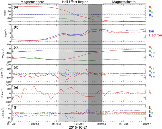
Figure 1. Magnetic reconnection in the dayside magnetopause observed by MMS3 on 2015 October 21, between 15:10:51 UT and 15:10:57 UT. (a) Three components of magnetic field; (b) ion and electron density; (c) three components of ion velocity; (d) three components of electron velocity; (e) L-component of current density; (f) three components of electric field. The black vertical dashed line represents the point of B L reversal. The black horizontal dashed lines represent the zero lines of each component. The gray horizontal dashed line in Figure 1(a) denotes the value of the guide field. The Hall effect region is indicated by gray shading.
Download figure:
Standard image High-resolution image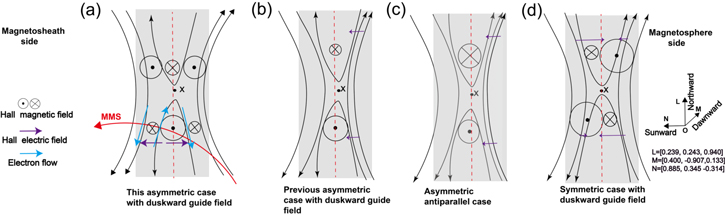
Figure 2. Hall patterns in different cases: (a) asymmetric case with duskward guide field in this event; (b) previous asymmetric case with duskward guide field; (c) asymmetric antiparallel case; (d) symmetric case with duskward guide field, with the LMN coordinates superimposed to the right. The circle with a dot is duskward B M , and the one with a cross is dawnward B M . The purple, blue, and red arrows represent the Hall electric field, electron flow, and MMS trajectory, respectively.
Download figure:
Standard image High-resolution imageFigure 1(a) shows that a bipolar B M perturbation is present during the crossing of the reconnection event, as represented by gray shading. The horizontal dashed line denotes the value of the background duskward guide field (–18.1 nT). In the magnetosphere, the bipolar B M starts with a negative perturbation with a peak value of –17.9 nT relative to the background guide field. The negative perturbation extends across the magnetopause into the magnetosheath. In the magnetosheath, at 15:10:54.4 UT, B M perturbation turns positive, and its value reaches the peak (+10.1 nT relative to the background guide field) at 15:10:54.75 UT.
3. Comparison with Previous Observations
The observations of the structure of the magnetic field in this event are depicted in Figure 2(a). The MMS3 trajectory through this event is represented by a red curve with an arrow. In this event, MMS3 observes bipolar variation of B M in the south branch. Under the condition of the duskward guide field and high asymmetry, the duskward B M perturbation is observed to be present across the magnetopause, whereas the dawnward B M is found at the magnetosheath side. Mozer et al. (2008a) investigated the structure of the reconnection diffusion region under similar asymptotic conditions using THEMIS observations. They found that the quadrupolar Hall magnetic field degenerated into an asymmetric bipolar Hall magnetic field, across the magnetopause. Consequently, only a unipolar Hall magnetic field was observed on the north and south sides of the X-line, as shown in Figure 2(b). The observed duskward B M in the event was in agreement with their results. However, the dawnward B M at the magnetosheath side in the south branch was not observed in a previous study. Therefore, the pattern of the B M perturbation is distinct.
4. Discussions
Previous observations and simulations have shown that the structure of the out-of-plane Hall magnetic field is mainly affected by the guide field and the asymmetry of the asymptotic conditions. Under different asymptotic conditions, Hall magnetic field can display various distributions. Symmetrical and antiparallel conditions produce a symmetrical Hall field pattern described as a quadrupolar Hall magnetic field and a bipolar Hall electric field (Mozer et al. 2002). Numerous observations have indicated that the existence of the guide field can considerably distort the Hall field pattern, and the distortion appears either on both sides of the current sheet or on opposite sides of the X-line (Figure 2(d)). To quantitatively study the influence of the guide field on the Hall magnetic field, Tharp et al. (2012) reported that the quadrupolar Hall magnetic field becomes more distorted as the guide field systematically increases in the Magnetic Reconnection Experiment. Moreover, the in situ observations have shown that the electron current deflection is caused by the interaction ( J H × B g ) between the Hall current ( J H ) and the guide field ( B g ) (Eastwood et al. 2010). Another nonnegligible reason is the asymmetry of the asymptotic conditions. The two poles of the Hall magnetic field disappear at the magnetosphere side, indicating that the Hall magnetic field pattern changes from quadrupolar to bipolar (Figure 2(c)); this phenomenon was also confirmed by observations from the THEMIS satellite (Mozer et al. 2008b) and had been interpreted in theory (Dai 2018). The combination of high asymmetry and the guide field induces an asymmetric bipolar Hall magnetic field (Pritchet & Coroniti 2004; Mozer et al. 2008a; see our Figure 2(b)). However, these previous results regarding quadrupolar or bipolar Hall magnetic fields cannot interpret the bipolar B M perturbation in this event.
Based on quantitative simulations, Sang et al. (2019a, 2019b) recently reported that the magnitude of the asymmetry and the guide field changes the degree of distortion of the quadrupolar Hall magnetic field. The results showed that the Hall magnetic field pattern tends to evolve from quadrupolar to hexapolar over time in the asymmetric magnetic reconnection (see Figure 1 in Sang et al. 2019a). The hexapolar Hall magnetic field also can be present in the asymmetric magnetic reconnection with the guide field (see Figure 7 in Sang et al. 2019b). Figure 2(a) shows the Hall patterns obtained from their simulation. In addition to the traditional quadrupolar Hall magnetic field, a bipolar Hall magnetic field appears at the side with high β of the current sheet, that is, the magnetosheath side in the present observations. In the south branch, the additional polar points to the dawnward direction. The observed B M distribution here is consistent with the two left poles of their results in terms of their location and polarity. The duskward B M occupies the region of the magnetopause, whereas the dawnward B M is present on the magnetosheath side. The observed bipolar B M could be two poles of a hexapolar Hall magnetic field.
The measured electric field, E , and the calculated − ( V i × B ) and − ( V e × B ) are compared in Figures 3(b)–(d); it is found that E ≈ − ( V e × B ) with a linear correlation coefficient of 0.89, but E ≠ − ( V i × B ) with a linear correlation coefficient of only 0.15 through the regions with B M perturbation. This indicates that ions are always demagnetized, whereas electrons are almost magnetized (Burch et al. 2016b). This supports the theory that the occurrence of ion–electron decoupling causes the Hall current system to flow around the peaks of the Hall magnetic field (Zhang et al. 2017), as shown by the bipolar variation in J L in Figure 1(e). We conclude that the observed bipolar B M is the two poles of the hexapolar Hall magnetic field obtained in the previous simulation. The ion inertial length ( D i ) of the plasma in the magnetosheath is 62 km. The normal speed of the magnetopause is +51 km s−1 calculated based on four MMS spacecraft observations of the B L reversal point (Russell et al. 1983). The thickness of the Hall regions can be estimated to be 99.5 km (∼1.6 D i ), with traversal times of 1.95 s. The traverse spatial scale of the Hall region is comparable to the ion inertial length (Zhang et al. 2008).

Figure 3. (a) Three components of the magnetic field: B L , B M , and B N ; (b)–(d) L-, M-, and N-components of the electric field, E , − ( V i × B ), and − ( V e × B ).
Download figure:
Standard image High-resolution imageThe behavior of the electrons associated with the new Hall magnetic field should also be studied. The MMS 3 observed the Hall field on the south side of the X-line in this event. At the magnetosheath side, the inflow electrons toward the X-line are observed along the +L direction between 15:10:54.1 UT and 15:10:54.7 UT (Figure 1(d)). Two electron outflows are observed on both sides of the electron inflow. The first outflow is observed along the –L direction between 15:10:52.8 UT and 15:10:54.1 UT in the central current sheet with the bias into the magnetosphere; this contributes to the Hall current for the duskward Hall magnetic field. This electron outflow at the Earth side of the magnetosheath electron inflow is often observed. The second outflow is observed along the –L direction between 15:10:54.7 UT and 15:10:55.0 UT in the magnetosheath; this contributes to the Hall current for the new dawnward Hall magnetic field. This electron outflow at the Sun side of the inflowing magnetosheath electron has not been previously observed.
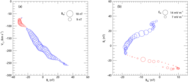
High-resolution measurements of the electric field from the MMS facilitate the evaluation of the distribution of the Hall electric field associated with the Hall magnetic field. Figure 1(f) shows the variation in the normal component of the electric field. During the period of the duskward Hall magnetic field, the Hall electric field points earthward, whereas the Hall electric field points sunward during the period of the dawnward Hall magnetic field. The peak values of the Hall electric field can reach –17.5 and 13.1 mV m−1. To further observe the structure of  and
E
N
, Figures 4(a) and (b) show the
and
E
N
, Figures 4(a) and (b) show the  distribution in the
B
L
−
V
i_L
coordinate frame and
E
N
distribution in the
distribution in the
B
L
−
V
i_L
coordinate frame and
E
N
distribution in the  coordinate frame. Here,
  is the magnitude of the Hall magnetic field after removing the guide field,
B
g
, that is,
is the magnitude of the Hall magnetic field after removing the guide field,
B
g
, that is,  . The two areas of
  are shown in Figure 4(a). The intensity of
  is expressed as the size of the circles. Red represents positive, and blue represents negative. The first part is the negative area of
  across the magnetopause when
B
L
ranges from –22.5 to 31.3 nT and
V
i_L
ranges from –264 to –105 km s−1; the second part is the positive area in the magnetosheath, where
V
i_L
reaches –72 km s−1, and
B
L
ranges from –33 to –22.5 nT. In Figure 4(b),
E
N
shows a distinct bipolar distribution, with the negative values mainly distributed in the negative
across the magnetopause when
B
L
ranges from –22.5 to 31.3 nT and
V
i_L
ranges from –264 to –105 km s−1; the second part is the positive area in the magnetosheath, where
V
i_L
reaches –72 km s−1, and
B
L
ranges from –33 to –22.5 nT. In Figure 4(b),
E
N
shows a distinct bipolar distribution, with the negative values mainly distributed in the negative  area across the magnetopause, and the positive values mainly in the positive
  area on the side of the magnetosheath.
Figure 4. (a)  (the value of the Hall magnetic field after removing the guide field,
B
g
) distribution with
B
L
versus
V
i_L
, and (b)
E
N
distribution with
(the value of the Hall magnetic field after removing the guide field,
B
g
) distribution with
B
L
versus
V
i_L
, and (b)
E
N
distribution with  vs.
B
L
. The positive
vs.
B
L
. The positive  and
E
N
are indicated by the red circles, and the negative
and
E
N
are indicated by the red circles, and the negative  and
E
N
are shown by the blue circles. The size of the circles indicates the magnitude of
and
E
N
are shown by the blue circles. The size of the circles indicates the magnitude of  and
E
N
.
and
E
N
.
Download figure:
Standard image High-resolution image
5. Summary
The MMS mission observed a magnetic reconnection event at the dayside magnetopause on 2015 October 21. This reconnection event occurred with a moderate guide field of
B
g
/
B
L_SH = 0.47 under the highly asymmetric condition of  and
and  . An abnormal
B
M
perturbation was observed during the crossing of this event. The abnormal indicates that
B
M
perturbation in this event cannot be interpreted by previously reported quadrupolar or bipolar Hall magnetic fields. A comparison with recent simulation indicates that the features of this perturbation are consistent with those of the counterpart of the hexapolar Hall magnetic field. Thus, based on this event, we provide the first observational evidence of the existence of a hexapolar Hall magnetic field in collisionless magnetic reconnection in magnetosphere. This evidence improves our understanding of the Hall effect.
. An abnormal
B
M
perturbation was observed during the crossing of this event. The abnormal indicates that
B
M
perturbation in this event cannot be interpreted by previously reported quadrupolar or bipolar Hall magnetic fields. A comparison with recent simulation indicates that the features of this perturbation are consistent with those of the counterpart of the hexapolar Hall magnetic field. Thus, based on this event, we provide the first observational evidence of the existence of a hexapolar Hall magnetic field in collisionless magnetic reconnection in magnetosphere. This evidence improves our understanding of the Hall effect.
High-resolution measurements of the plasma and field from the MMS facilitate a comprehensive investigation of the hexapolar Hall effect. The electron flow mode associated with the hexapolar Hall magnetic field is unique. In addition to the traditional electron outflow in the central current sheet from the X-line, electrons flow from the X-line at the Sun side of the inflowing electron in magnetosheath. The Hall electric field associated with the two poles of the hexapolar Hall magnetic field has a back-to-back style, that is, the Hall electric field associated with the left pole of the hexapolar Hall magnetic field points to the left, and that associated with the middle pole points to the right. The mechanism behind these features associated with the hexapolar Hall effect requires further study.
MMS data can be accessed at https://lasp.colorado.edu/mms/sdc/public/. We acknowledge all the MMS instrument teams. This work was supported by the National Natural Science Foundation of China (grant Nos. 41731070, 41874176, and 41814175) and the Specialized Research Fund for State Key Laboratories. This work was also supported by the Strategic Pioneer Program on Space Science, Chinese Academy of Sciences, grant No. XDA15052500 and Grant No. XDA 15011400, and partially by the Chinese Meridian Project.