

Abstract
Diabetes is a typical lifestyle-related disease and blood glucose measurement plays an important role in daily health management and appropriate treatment for patients. Continuous glucose monitoring system (CGMS) is becoming common for general patients. In this paper, an optically-powered battery-less glucose sensor device with a 12 mm diameter is presented. The sensor is expected to be used for next-generation CGMS. The sensor is equipped with series-connected ultra-small photovoltaic cells as the power source. Circuit design and characterization, fabrication, and evaluation of a wireless sensor device are presented to demonstrate the feasibility of the proposed sensor architecture.
Export citation and abstract BibTeX RIS
Diabetes mellitus is a disease in which blood glucose levels remain high due to abnormal insulin secretion in the body, and the number of patients is increasing worldwide. 1–4) Persistently high blood glucose levels increase the likelihood of various complications such as diabetic neuropathy and diabetic retinopathy. 5–8) About 90% of diabetics have type 2 diabetes, and blood glucose levels can be lowered by improving diet and exercise habits, but if necessary, patients are given oral medication or insulin injections. 9–11) Thus, daily health management through blood glucose measurement is important to improve lifestyle and provide appropriate treatment to patients.
Currently, diabetic patients can use self-monitoring of blood glucose (SMBG) to measure and manage their own blood glucose levels in their daily life. SMBG can directly measure blood glucose levels by using a puncture needle to draw blood from a fingertip or other source and have the sensor absorb the blood. However, the need to measure three to four times a day and the pain caused by puncture each time the measurement is made are burdensome for patients. 12–15)
Continuous glucose monitoring system (CGMS) has become increasingly popular in recent years to relieve this burden. 16) CGMS is a system that continuously measures the glucose concentration in the interstitial fluid by attaching a small wireless sensor device with a subcutaneous flexible probe to the upper arm. 17–19) Glucose concentration can be read out by holding the reader over the sensor device, which can continue measuring for up to 14 days after it is attached. Thus, trends in the diurnal variation of blood glucose levels over several days and the presence of hypoglycemia during sleep can be confirmed. However, current CGMS devices use batteries as the power source, making them about 30 mm to 40 mm in diameter, and there are concerns about aesthetic issues due to the conspicuousness of the sensor and the risk of contact accidents. Therefore, there is an expectation for miniaturization of the device.
In this study, we fabricate and demonstrate the functionality of a battery-less miniaturized glucose sensor based on an optical power transfer technology 20–23) with ultra-small PV cells as the power supply unit.
The circuit in this study is based on the circuit described in our previous publication. 24) We newly implemented non-photovoltaic two-bias generation circuits. One is for optical powering (primary bias generator) and the other is for electrochemical glucose measurement (secondary bias generator).
The block diagram of the optically-powered miniaturized glucose sensor is shown in Fig. 1. The device realized in this study consists of an optically-driven, intermittent powering circuit and an electrochemical glucose measurement circuit. The electrochemical glucose measurement circuit performs amperometric glucose measurement for each pulse voltage generated by the optical powering circuit. A conventional glucose oxidase (GOD)-based flexible glucose sensor was employed for the sensing part. An LED is driven by a current proportional to the amperometric glucose sensing current for data output. Since the largest part of the load current is the LED current, measured glucose concentration is optically displayed in a pulse duration modulation manner.
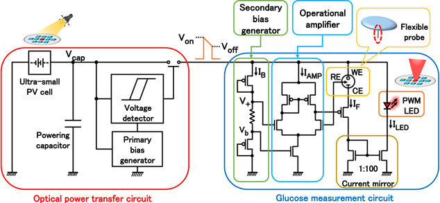
Fig. 1. Block diagram of the proposed glucose sensor.
Download figure:
Standard image High-resolution imageThe measurement flow of the device is as follows. First, light is irradiated to the series-connected ultra-small photovoltaic (PV) cells, and the generated photocurrent directly charges the powering capacitor. As illumination continues, the voltage of the powering capacitor Vcap rises. In the previous works, 20–24) the primary bias generator generates reference voltages from PV cells, and it made the switching voltages illumination-dependent. In this work, we employed a non-PV, simple ladder-type reference voltage generator. 25–28)
The voltage detector controls the CMOS switch between the powering capacitor and the load circuit at on-voltage Von and off-voltage Voff respectively. The Von and Voff are determined by the reference voltage input from the primary bias generator. When Vcap exceeds Von, the CMOS switch is closed and power is supplied to the load circuit. 20–24,29,30) During the power supply phase, the value of Vcap decreases. When Vcap falls below Voff, the CMOS switch is opened and the system is in the charging phase. Therefore, the output of the optical powering circuit becomes a pulsed format. The pulse-shaped powering pulse drove the secondary bias generator circuit, an operational amplifier, an electrochemical glucose sensor, and an LED in the glucose measurement circuit.
To obtain a correct electrode response in amperometric glucose measurements, it is necessary to maintain a constant potential difference (oxidation voltage) between the WE (working electrode) and RE reference electrode). Therefore, the secondary bias generation circuit generates a voltage V+ that is approximately 0.5 V lower than the input voltage to the measurement circuit. It is realized with a diode-connected PMOS transistor.
The operational amplifier plays a core role in the amperometric glucose measurements. It keeps the voltage between the WE and RE of the glucose sensor at 0.5 V. Here, the Faraday current IF, which is proportional to the glucose concentration, flows from WE to the CE (Counter Electrode), and the current is amplified by the current mirror circuit to drive the LED.
Here, the total current consumed by the glucose measurement circuit, ITotal is estimated as Eq. (1).

The secondary bias generation circuit is designed with a smaller current flow than the other parts of the circuit, we can assume IB is less dominant in Eq. (1). The operational amplifier operates only on feedback, keeping the operating point at its designed state. Therefore, IAMP can also be regarded as almost constant. The current ILED flowing in the LED is the Faraday current IF amplified by the current mirror ratio. Since the current mirror ratio was set to 1:100 in this study, Eq. (1) can be expressed by Eq. (2), indicating that the total current consumption depends on the faraday current IF.

On the other hand, the optical power transfer circuit supplies a pulse voltage by discharging the capacitor when Vcap is between Von and Voff, so that a single pulse voltage provides the amount of charge in Eq. (3).

Therefore, the pulse duration of one pulse voltage is expressed by Eq. (4).

Von and Voff in Eq. (3) are values determined by the voltage detector design. The capacitance C is a fixed parameter of the off-chip element. It means Qpulse is fixed. Since ITotal depends on Faraday current IF, it can be seen that the Faraday current determines the pulse duration Tpulse.
The current mirror ratio of 1:100 between the Faraday current and the LED operation current was decided from viewpoints of detectability by currently available photosensing technology and the available charge for single measurement operation. The Faraday current of the glucose sensor used in this work is in the range of 1 ∼ 10 μA. Setting the current mirror ratio as 1:100, the LED current is in the range of 100 ∼ 1000 μA. It also gives 1 ms or longer LED pulse duration, with a powering capacitor of 1 ∼ 10 μF. Both the illumination intensity and pulse duration match conventional photosensing technologies.
Figure 2 shows the simulation results of the pulse duration of the pulse voltage when the Faraday current is 100 nA, 1 μA, and 10 μA. The larger the Faraday current, the larger the current consumption (ITotal) in the measurement circuit, and thus the pulse duration of the pulse voltage becomes shorter. In other words, faraday current and pulse duration are inversely correlated, and the Faraday current can be estimated from the operating time of the entire circuit. In addition, since LED is operated by the pulse voltage from the optical power transfer circuit, the LED emission time and Tpulse are equal. Therefore, the glucose-dependent Faraday current can be estimated by the optical pulse duration of the LED.
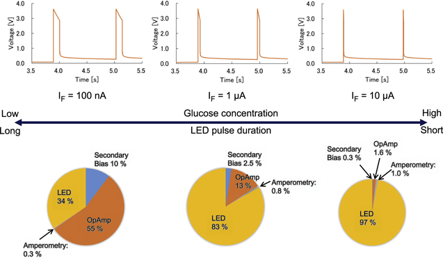
Fig. 2. Simulated operation voltage traces with different Faraday currents.
Download figure:
Standard image High-resolution imageSince all the power-consuming (load) blocks: the secondary bias generator, the operational amplifier, the amperometric glucose sensor, and the LED are operated by the same powering node, the power consumption ratio between blocks is proportional to the currents, IB: IAMP: IF: ILED. It depends on the glucose concentration. The power breakdowns are also shown in Fig. 2.
Based on Fig. 1, we designed a CMOS chip using a 0.35 μm 2-poly 4-metal standard CMOS process and fabricated an optically-powered miniaturized glucose sensor device. Figure 3 shows the device structure. The dimensions of the main body of the sensor are 12 mm in diameter and 7 mm in thickness. The device consists of a transparent package fabricated by a 3D printer, a flexible glucose sensor that can be measured by amperometry, and two printed circuit boards (PCBs) A and B. The internal PCB A has nine series-connected PV cells and LED on its surface and a 10 μF capacitor on its back. The PCB B is equipped with a CMOS chip. Some interconnecting wires were used to connect the two PCBs.
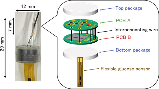
Fig. 3. Fabricated optically-powered miniaturized glucose sensor device.
Download figure:
Standard image High-resolution imageTo verify the functionality of the fabricated miniaturized glucose sensor device, in vitro experiments using glucose solutions were performed. A total of 11 solutions were used for the measurements: PBS and glucose solutions were prepared from 0 mg dL−1 to 500 mg dL−1 at 50 mg dL−1 intervals. The flexible glucose sensor part was immersed in glucose solutions, and the sensor was illuminated by an LED light source. The LED operation signal was taken via sensing wires. The results are shown in Fig. 4. The optical pulse duration at each concentration as a function of the glucose concentration is shown in Fig. 5.

Fig. 4. Measured operation voltage traces at each glucose concentration.
Download figure:
Standard image High-resolution image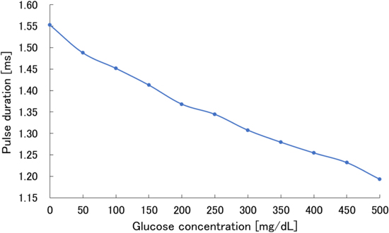
Fig. 5. Relationship between glucose concentration and the LED light pulse duration (measured results).
Download figure:
Standard image High-resolution image
Figures 4 and 5 show that the pulse duration becomes shorter as the glucose concentration increases, indicating that there is an inverse relationship between the glucose concentration and the pulse duration. Thus, it was confirmed that the device can be driven by light and the glucose concentration can be estimated from the optical pulse duration output from the LED.
In this study, we designed and demonstrated a battery-less glucose sensor operated by an optical power transfer scheme. It employed the electrochemical glucose measurement circuit compatible with data transmission using PWM LED emission. The fabricated optically-powered glucose sensor device is with a main body of 12 mm in diameter and 7 mm in thickness. Functional verification confirmed that the device is capable of measuring glucose concentration only by irradiating the device with light. The glucose concentration was successfully read out as the light pulse duration from the LED.
As a future work, we will work on the realization of a CGMS device that can be driven by ambient light and the digital display of glucose concentration.
It is also important to characterize the long-time performance of the sensor system. In this work, we only confirmed that the circuit operation with nearly ideal, new amperometric flexible glucose sensor slip. It is generally understood that the GOD-based glucose sensor employed in this work has a lifetime of up to several weeks or months. In the next work, we will confirm that the present sensor system can keep operating as the amperometric flexible glucose sensor slip keeps its functionality.
Before applying this device to the application, a calibration scheme should be established. In the present glucose sensor system, the largest characteristic variation comes from the amperometric flexible glucose sensor slips. The conversion factor from the glucose concentration to the Faraday current is different between sensor slips. As same as the current CGMS technologies, this system will require calibration for each glucose sensor slip. The calibration is also effective to compensate for other mismatches between devices.
Acknowledgments
The CMOS chips were designed with the support of the VLSI Design and Education Centre (VDEC), the University of Tokyo in collaboration with the Cadence Corporation and the Mentor Graphics Corporation.