
Abstract
Non-coherent Σ3{111} grain boundaries (GBs) with a positive deviation in the tilt angle (θ〈110〉 > 70.5°) exhibit a high recombination activity in high-performance multicrystalline silicon ingots. Most of the GB segments are composed of edge-type dislocations with the Burgers vector b of a/3〈111〉, unlike Lomer dislocations with b = a/2〈110〉 observed for negative deviations, arranged on coherent Σ3{111} GB segments. Stretched 〈110〉 reconstructed bonds along the tilt axis are introduced so as not to form dangling bonds, and large strains are generated around the dislocation cores. Oxygen and carbon atoms segregating due to the strains would induce the recombination activity.
Export citation and abstract BibTeX RIS

Content from this work may be used under the terms of the Creative Commons Attribution 4.0 license. Any further distribution of this work must maintain attribution to the author(s) and the title of the work, journal citation and DOI.
Large-scale multicrystalline silicon (mc-Si) ingots with a high production ratio, grown by the cost-effective cast-growth methods, are one of the most important materials in the photovoltaic (PV) market. 1) Especially, high-performance (HP) mc-Si with a low dislocation density, in which high density of random-angle grain boundaries (RAGBs) are intentionally introduced so as to release the thermal stress during the growth, 2) has been widely applied to commercial solar cells, and the efficiency of an HP mc-Si solar cell reaches the world record of 22.3% for mc-Si solar cells. 3) The estimated efficiency is a few % lower in comparison with monocrystalline Si solar cells. One of the major origins of the efficiency loss is the carrier recombination at GBs. 3) It is known that as-grown HP mc-Si ingots exhibit a high recombination activity at many GBs including RAGBs, small-angle grain boundaries (SAGBs), and coincidence site lattice (CSL) GBs described with Σ numbers. However, most of the GBs, except for SAGBs and some CSL GBs, lose their activity after the standard cell processing (gettering and hydrogenation). 4) We, therefore, need to understand and then reduce the recombination activity at those remaining GBs, in order to further improve the solar cell efficiency. 5)
Coherent Σ3 twin boundaries on {111}, in which the GB plane corresponds to the mirror plane of the twin, are the typical tilt-angle GBs in cast-grown Si ingots. More than 50% of the GBs in standard mc-Si ingots (grown without seeds) are Σ3{111} GBs, 6) since they are easily nucleated at the three-phase boundaries between the melt and two different Si grains. 7) Also, they are unintentionally nucleated on the crucible during the mono-cast growth. 8) Even in HP mc-Si, a significant number of Σ3{111} GBs are generated with growth in consuming RAGBs. 2,9) During the cast-growth, especially for HP mc-Si ingots, multiple competition of grains with different crystallographic orientation takes place, and this results in a frequent introduction of non-coherent Σ3{111} GBs with a misorientation in the tilt angle and/or with a misalignment in the GB plane. 10) Even though coherent Σ3{111} GBs would be harmless in solar cells, non-coherent Σ3{111} GBs can adversely affect the PV properties. 11,12) Recently, faceted Σ3 GBs, whose GB planes are not aligned just on {111} but on {111} and {112}, are examined, and impacts of the misalignment on PV and structural properties are discussed. 4,13) In the present work, to discuss impacts of the other factor of misorientation, we have examined the recombination activity of non-coherent Σ3{111} GBs with a positive deviation in the tilt angle.
A wafer was cut from an HP mc-Si ingot for commercial solar cells. Two-dimensional (2D) distribution of GBs on the wafer was visualized by optical microscopy [e.g. Fig. 1(a)], and the GB character was then analyzed by electron backscatter diffraction (EBSD) to select Σ3 GBs [Fig. 1(b)]. 14) The recombination activity of a Σ3 GB was determined by micro-photoluminescence (μ-PL) imaging [Figs. 1(c)–1(e)], 15) using a PL measurement system (Hamamatsu Photonics EPL-100s). 16) The PL contrast CGB was defined as CGB = (I0 − IGB)/I0, where IGB and I0 were the PL intensity at the GB and in the background region, respectively. After the measurement, a thin foil for high-angle annular dark-field scanning transmission electron microscopy (HAADF-STEM) and needles for atom probe tomography (APT) were cut from the Σ3 GB by focused-ion-beam milling 17) (see Figs. S1(a), S2(a), and S3(a) in the supplementary data (available online at stacks.iop.org/APEX/14/011002/mmedia)). The atomic arrangement around the GB was examined by HAADF-STEM with a JEOL ARM200F analytical microscope. Three-dimensional (3D) distribution of impurity atoms at the GB was determined by APT with a local electrode atom probe (Ametek, LEAP4000X HR). A 3D atomic map was reconstructed with the Integrated Visualization and Analysis Software protocol. 18) The detection limit for impurity atoms was about 0.01 at% with a spatial resolution of 0.4 nm. 19) The GB location in the reconstructed 3D atomic map was determined with pole patterns in 2D Si density maps. 17)

Fig. 1. (Color online) (a) GBs in an HP mc-Si wafer observed by optical microscopy and (b) their GB character revealed by EBSD. (c)–(e) PL images of the Σ3 GBs within the squares in (b). The PL contrast CGB and the deviation in the tilt angle Δd for each GB are indicated on each figure.
Download figure:
Standard image High-resolution imageA non-coherent Σ3 GB with a deviation in the tilt angle exhibits strong PL contrast [CGB = 0.6, Fig. 1(c)], unlike coherent Σ3{111} GBs exhibiting no PL contrast (as shown in Fig. 1(d) and Fig. S2(d) in the supplementary data). The tilt angle around 〈110〉, θ〈110〉, is +7° off from the ideal angle of θ〈110〉 = 70.5° for coherent Σ3{111} GBs [Figs. 2(a) and 2(b)]. The GB segments expand parallel to the tilt axis and slightly inclined from {111} in the adjacent grains [Fig. 2(c)]. Only a fraction of GB segments expand so that the adjacent grains are macroscopically symmetric with respective to the GB plane, and most GB segments align as asymmetric [Fig. 2(c)]. No extrinsic defect except GB dislocations, such as impurity precipitates, is observed on those segments [Fig. 2(d)].
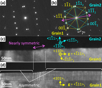
Fig. 2. (Color online) (a) Transmission electron diffraction (TED) pattern of the Σ3 GB shown in Figs. 1(c) and 1(b) indices of the diffraction spots in (a). Dark-field (DF-) TEM of the GB taken with the incident direction (c) parallel to and (d) inclined from the tilt axis.
Download figure:
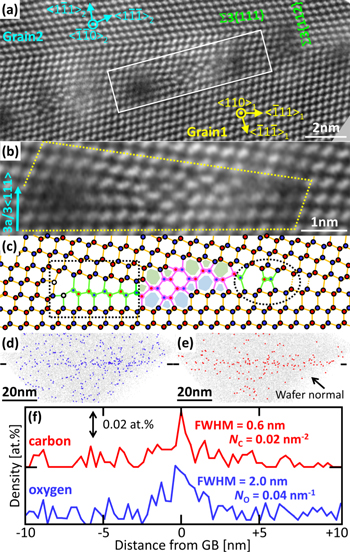
Standard image High-resolution imageThe asymmetric segments in Fig. 2(c) are composed of arrays of GB dislocations lying on the GB plane of coherent Σ3{111} GBs [Figs. 3(a) and 3(b)]. This GB is not a RAGB but can be considered as a CSL GB with Σ = 3, as expected from the Brandon's criterion; 20) (Σ = 3)0.5 7°/15° = 0.8 < 1. Those GB dislocations are edge-type with the Burgers vector b of a/3〈111〉, determined using the GB circuit mapping. 21) A similar isolated GB dislocation is reported on a recombination-active Σ3{111} GB. 11) They would arrange at similar intervals of about 2.5 nm so as to compensate for the misorientation of +7°, and therefore tan−1(b = 0.314 nm/2.5 nm) ∼ 7°. There exists no dangling bond [Fig. 3(c)], suggesting no deep level at the GB dislocations.

Fig. 3. (Color online) (a) HAADF-STEM image of the asymmetric Σ3 GB segment shown in Fig. 2(d). (b) Enlarged image of the boxed GB dislocation in (a), and (c) the corresponding structural model. (d) 2D distribution of hydrostatic tensile stress calculated around a GB dislocation. Projected 3D impurity maps for (e) oxygen and (f) carbon atoms. The black lines in each figure represent the GB location. (g) The concentration profile across the GB for oxygen and carbon impurities, estimated by APT.
Download figure:
Standard image High-resolution imageAPT reveals the segregation of oxygen and carbon atoms, that would be inherited from the crystallization furnace and the crucible, 22) almost homogeneously on the asymmetric segments [Figs. 3(e) and 3(f)]. No apparent oxygen agglomerate (SiOx ) is observed, showing that oxygen atoms would be isolated neutral interstitials. Therefore, oxygen atoms would segregate at the tensile side of GB dislocations via elastic interactions with dislocations, rather than at dislocation cores via electronic interactions. 23) The concentration profile for oxygen peaks on the GB plane, with the full-width at half maximum of 1.8 nm [Fig. 3(g)]. The profile is compared with the 2D distribution of hydrostatic tensile stress around a GB dislocation [Fig. 2(d)], calculated elastically. 24) This indicates the oxygen segregation at the atomic sites under tensile stresses above 1.5–2.0 GPa, as demonstrated in the oxygen segregation at GB dislocations of another kind, 18,24) SAGBs, 23,24) and CSL GBs. 19,25) Similarly, no apparent carbon agglomerate (SiC) is observed, suggesting that carbon atoms would exist as isolated substitutional atoms and they would segregate at compressive atomic sites. 13,26) The segregation ability of the asymmetric segments for oxygen NO is the same order as that for carbon NC (about 0.06 nm−2). The concentration of metallic impurities, such as iron and nickel, would be lower than the detection limit of APT at the segments. 27)
In the nearly-symmetric segments shown in Fig. 2(c), asymmetric Σ3{111} GB segments decompose into a reconstructed SAGB and coherent Σ3 GBs on {111} and {112} [Fig. 4(a)]. The former GB is composed of a complex unit structure free from dangling bonds with the periodicity of 7.5 nm [Fig. 4(b)]. The unit cell model shown in Fig. 4(c) involves a Frank-type partial dislocation (b = a/3〈111〉) with an intrinsic stacking fault (the boxed area), a {111} defect with the displacement vector of a/5〈111〉 28) (the encircled area), and the nano-domain shown in pink. The nano-domain is rotated by 38.9° around the tilt axis of 〈110〉 with respect to the host Si crystal, forming coherent Σ9{112} GB segments composed of 5- and 7-membered rings. 25) The total displacement vector in the unit cell is 3a/3〈111〉 [Fig. 4(b)], and it can just compensate for the misorientation of +7°. The atomic arrangement around the Frank partial dislocation is similar to that of the GB dislocation shown in Fig. 3(b), and therefore the strains around those dislocations would be similar. Actually, the Frank partial dislocations exhibit strong dark contrast in HAADF-STEM due to strains [Fig. 4(a)], and it is similar to the contrast at the GB dislocations [Fig. 3(a)]. Meanwhile, strains at the edge of the {111} defect, with a short displacement vector of a/5〈111〉, would be rather small in comparison with the Frank partial dislocations [Fig. 4(a)]. Also, the Σ9 twin domain exhibits no apparent dark contrast, suggesting small strains. As a result, it is expected that the total strain, as well as the segregation abilities for oxygen and carbon, for the unit cell would be about a half in comparison with those for three GB dislocations.
Fig. 4. (Color online) (a) HAADF-STEM image of the nearly symmetric Σ3 GB segment shown in Fig. 2(c). (b) Enlarged image of the unit cell of a reconstructed SAGB boxed in (a), and (c) the corresponding structural model. Projected 3D impurity maps for (d) oxygen and (e) carbon atoms. The black lines in each figure represent the GB location. (e) The concentration profile for oxygen and carbon impurities, that is expected to be obtained from the GB segment.
Download figure:
Standard image High-resolution image
Although it is difficult to select artificially decomposed segments into APT specimens due to their small fraction, we happened to obtain an APT data in which oxygen and carbon atoms would segregate at a decomposed segment [Fig. 4(f)]. The segregation abilities for oxygen and carbon are about a half in comparison with asymmetric Σ3{111} segments, and the GB plane is inclined by a few degrees with respect to the asymmetric Σ3{111} segments [see Figs. 3(f) and 4(e)]. Coherent Σ3{112} GB segments of small area would scarcely affect the segregation ability of the decomposed GB.
For comparison, we also examine non-coherent Σ3 GBs with a misalignment in the GB plane; i.e. Σ3 GBs composed of {111} and {112} facets. It is shown that such GBs can exhibit PL contrast via the impurity segregation due to strains around the facet junctions. 13) Actually, a faceted Σ3 GB is segregated with oxygen and carbon atoms (NO ∼ 0.03 nm−2 and NC ∼ 0.02 nm−2, see Fig. S4 in the supplementary data), and it exhibits PL contrast [CGB = 0.2, Fig. 1(e)]. Coherent Σ3{111} GBs exhibit no PL contrast [Fig. 1(d)], since they do not induce defect levels with electrical activities 29) and they are scarcely segregated with impurities inducing defect levels, 10,17) as theoretically expected. 30,31) The PL contrast CGB is almost proportional to the segregation abilities NO and NC, indicating that the recombination activity of non-coherent GBs would be connected with their segregation abilities for oxygen and carbon, due to strains generated inevitably in the non-coherent structures.
Finally, we discuss the impacts of positive deviation in the tilt angle on structural properties of Σ3{111} GBs. It is shown that Si tilt boundaries with θ〈110〉< 70.5° can be described by a combination of Lomer dislocations without additional dangling bonds. 32) Therefore, Σ3{111} GBs with a negative deviation in the tilt angle would contain Lomer dislocations with the Burgers vector b of a/2〈110〉, so as to compensate for the deviation. Meanwhile, for the case of positive deviation, GB dislocations with b = a/3〈111〉 are introduced. At the dislocation cores, two stretched 〈110〉 reconstructed bonds [see the white circles in Fig. 3(c)], that would be an origin of large strains in the non-coherent Σ3{111} GBs, are introduced so as not to have dangling bonds. It is considered that, 33) Si tilt GBs with θ〈110〉 > 70.5°, such as Σ3{211} 34,35) and Σ9{411} 25) GBs, inevitably have such stretched bonds and therefore have higher GB energy, in contrast to GBs with θ〈110〉 < 70.5° such as Σ3{111} and Σ9{221} 35) GBs without such bonds. On the analogy of Si tilt GBs with θ〈110〉 < 70.5°, 32) edge-type dislocations with b = a/3〈111〉 may be a base component of Si tilt GBs for θ〈110〉 > 70.5°. Also, complex reconstructed structures shown in Fig. 4(c) are rarely introduced on the non-coherent Σ3{111} GBs. The intermediate structure would be formed so as to reduce the stretched bonds by introducing low-energy CSL GB segments.
In conclusion, the recombination activity of Si Σ3{111} GBs with a positive deviation in the tilt angle is examined. Most GB segments are composed of edge-type dislocations with b = a/3〈111〉 arranged on coherent Σ3{111} GB segments. Stretched 〈110〉 reconstructed bonds along the tilt axis, inducing large strains, are introduced at the dislocation cores so as not to form dangling bonds, and oxygen and carbon atoms segregating due to the strains would induce the recombination activity. Complex reconstructed structures are rarely introduced instead of the GB dislocations, presumably due to the reduction of the stretched bonds by introducing low-energy CSL GB segments.
This work is supported by JST/CREST, Grant No. JPMJCR17J1 (2017-2023), GIMRT Program in IMR, Tohoku University (No. 20M0403), and "Network Joint Research Center for Materials and Devices: Dynamic Alliance for Open Innovation Bridging Human, Environment and Materials" in ISIR (No. 20201231).