
Abstract
Transmission extreme ultraviolet microscopy is applied to the staining-free observation of a poly(styrene–methyl methacrylate) (PS/PMMA) blend. At a photon energy of 92 eV, the imaginary part of the atomic scattering factor for oxygen, which represents the absorption, is four-times larger than that of carbon, and microstructures can be visualized by the contrast resulting from the presence of oxygen. Based on the signal to noise ratio of the images, we consider the optimum photon energy and sample thickness for common polymer blends. Finally, a practical high contrast of 30% is successfully demonstrated for the PS/PMMA thin film.
Export citation and abstract BibTeX RIS

Content from this work may be used under the terms of the Creative Commons Attribution 4.0 license. Any further distribution of this work must maintain attribution to the author(s) and the title of the work, journal citation and DOI.
In various industries, including automotive engineering and smartphone manufacturing, there are growing demands for polymers as structural materials. A promising method for enhancing resistance against heat or mechanical impact, inherent in these applications, is to employ polymer blends or polymer alloys composed of two or more polymer elements. In polymer blends, the elements are in a phase-separated construction, having various microstructures, e.g. a bicontinuous structure or a sea-island structure. Considerable effort has gone into controlling these structures on the spatial scale between 10 nm to several μm, in order to obtain enhanced properties.
In studying the deformation and fracture of various polymer blends, the material properties against stress and heat have been investigated.1–4) In these studies, in situ observations that visualize the spatial and temporal changes of the microstructure are of primary importance. Several researchers have reported in situ straining of polymer thin films in a high voltage electron microscope.5,6) Dynamic observations require three primary features, namely a high spatial resolution at the molecular scale, a short observation time, and a high contrast between the polymer elements. Electron imaging techniques7–9) can realize the first two requirements, however, they tend to require a staining procedure10) to enhance the image contrast, which may change the mechanical properties of the polymers. Other scanning methods such as atomic force microscopy11–14) and scanning transmission soft-X-ray microscopy (STXM)15–19) have been applied, since they can provide staining-free imaging to give a sufficiently high spatial resolution map of light elements. However, these methods require relatively long observation times, ranging from several minutes to a few hours.
Full-field extreme ultraviolet (EUV) microscopy using light with a photon energy of 92 eV (or a wavelength of 13.5 nm) is an anticipated alternative staining-free observation method for polymer materials. We have previously reported the high resolution and short observation time of EUV microscopy, employing full-field microscopes composed of a multilayer-mirror objective.20,21) We have successfully demonstrated diffraction-limited spatial resolutions below 30 nm by observing the reflection images of a lithography mask.22,23) An EUV microscope is also capable of high-speed observations. Another transmission-type microscope has been reported employing a laser-produced plasma (LPP) light source,24,25) which has been successfully applied to the observation of cerebral slices of a mouse within an exposure time within 10 ns.26) In this paper, we will discuss a third advantage of the EUV microscope, namely, the elemental contrast in polymer samples, as a preliminary study for dynamic observations. To simplify the discussion, the following analysis is restricted to polymer blends of two compositions. First, we describe a simple numerical model giving the contrast and noise of a transmission EUV image. Then, we calculate the signal to nose ratio (SNR) of images as a function of the observation photon energy and sample thickness, to estimate better observation conditions with high SNR. Finally, a common polymer blend, poly(styrene–methyl methacrylate) (PS/PMMA), is observed under high SNR conditions.
We consider a polymer blend film made of two different compositions (i = 1, 2). At a photon energy of E (or a wavelength of λ), the transmittance of a film with a thickness of d is given as27)

where  are the absorption coefficients

where  is the classical electron radius and
  and
and  represent the mass density and imaginary part of the atomic scattering factor for the jth atomic element in the composition. Figure 1 shows
  as a function of atomic number, z.28) At a photon energy of 92 eV, we observe discontinuities for Be and Si, based on the K- and L-absorption edges of these light elements. In addition, a relatively large change of the scattering factor occurs for elements between these discontinuities. For example, oxygen and nitrogen have scattering factors four- and two-times larger than that of carbon. This implies that image contrasts can be expected arising from the differences in the scattering factors. The density used in TEM and hard X-ray microscopy should have a small effect since it varies within a few tens of percent in most polymer materials. To find the optimal observing conditions against the photon energy and thickness, we consider the SNR of an EUV image. Figure 2(a) describes the transmittances of the different compositions for 300 nm thick PS/PMMA blends. Below the carbon K-edge (E = 284 eV), PMMA containing oxygen with a large scattering factor gives a lower transmittance than that for PS made of carbon and hydrogen. The SNR for EUV images can be computed from the transmittance spectra, as shown in Fig. 2(b). We regard the signal, s, as the image contrast, and thus,
  Since the shot noise (or photon noise), which is proportional to the square root of the photon number, N, on a detector has the greatest effect on the imaging, we consider the noise, n, to be
  The photon number relates to the average transmittance, and thus,
  Then, the SNR can be estimated by applying the following relation:

In the lower energy region, the decreased transmittances increase both the signal and noise. These two effects are balanced around 70–90 eV to give the highest SNR. We note that at least a three-times better SNR can be expected in this EUV region, compared to the carbon- and water-window region that have been applied to polymer observations.13–17) The SNR spectra of common polymer blends made of polycarbonate (PC, C16O3H8, 1.20 g cm3), poly(ethylene terephthalate) (PET, C10O4H8, 1.38 g cm−3), and polybutylene terephthalate (PBT, C12O4H12, 1.34 g cm−3) are shown in Fig. 3(a). The maximum SNRs are observed for photon energies between 70 and 90 eV, as for PS/PMMA. Also, for PC-based blends, we can expect an order of magnitude higher SNR compared to that obtained in the carbon- or water-window region. These results also indicate that a larger difference in the oxygen contents between the two polymer elements can yield a better SNR. Figure 3(b) shows the SNR values as a function of the sample thicknesses. We observe broad peaks at thicknesses between 370 and 480 nm. Allowing a 15% reduction from the maximum SNR, which has little effect on the image quality in most cases, the sample thickness can be selected to be between 260 and 620 nm. The results in Fig. 3 suggest that for a high SNR observation, the selection of the observation energy is of primary importance, and we can select the thickness from a relatively wide range according to the convenience of the sample preparation.
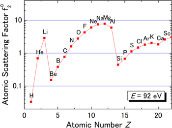
Fig. 1. (Color online) Imaginary part of the atomic scattering factor, f02, representing absorption at a photon energy of 92 eV, as a function of atomic number, z.
Download figure:
Standard image High-resolution image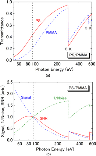
Fig. 2. (Color online) Parameters describing the SNR of a transmission EUV image: (a) transmittance spectra for 300 nm thick PS (C8H8, 1.00 g cm−3) and PMMA (C5O2H8, 1.18 g cm−3) films, (b) calculated signal, 1/noise, and SNR spectra, normalized to the values at a photon energy of 92 eV.
Download figure:
Standard image High-resolution image
Fig. 3. (Color online) SNR curves for PS/PMMA, PET/PC, and PBT/PC blends: (a) SNR spectra for 300 nm thick films, (b) SNR as a function of the film thickness. The curves show calculation results at a photon energy of 92 eV.
Download figure:
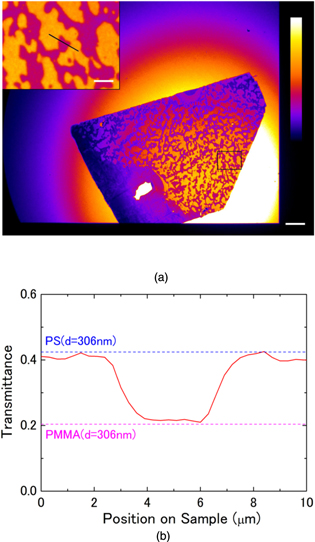
Standard image High-resolution imageTo demonstrate staining-free visualization of microstructures of a polymer blend, a PS/PMMA thin film was observed with a lab-scale transmission EUV microscope.24) PS (TSKstandard, Mw/Mn = 1.04, Mw = 190 000) and PMMA (PolymerSource, Mw/Mn = 1.09, Mw = 151 000) were used as starting materials. A solution of these two polymers in equal volumes was dissolved in benzene and stirred at room temperature for 12 h, then lyophilized to synthesize the PS/PMMA blend powder. We then applied a pressure of 50 MPa and heat of 150 °C for 1 h to form a polymer film. The resultant polymer thin film was sectioned with a cryomicrotome and placed on a SiN-membrane grid (nominal thickness: 300 ± 50 nm). A transmission EUV image observed at a photon energy of 92 eV is shown in Fig. 4(a). Bicontinuous structures in the sample were clearly observed within an exposure time of 10 ns. The bright circular area shows an image of the high-temperature plasma in the light source. The photon dose was estimated to be 0.04 photons nm−2 on the sample plane. The exposure was repeated 18 times to precisely adjust the focus, however, no structural change due to irradiation damage was observed. Figure 4(b) shows the cross-sectional transmittance across the phase boundaries, calculated along the black line in the inset of Fig. 4(a). The transmittances of the PS and PMMA, showing step-like structures, were estimated to be 0.41 and 0.22, corresponding to an image contrast of 0.30. The results clearly demonstrate that transmission EUV microscopy can visualize the structure of polymer blends with a high contrast, dependent not only on the density but also the composition of the light elements in the sample. Also, the contrast was reduced by 14% compared to the theoretical transmittances indicated by the dashed lines in the figure. One probable reason for this degradation is that each phase composed of a primary polymer contains a small amount of the other polymer, since the sample has not reached thermal equilibrium. This fact implies that EUV microscopy can provide information about the composition, as well as the shape of the microstructure in the polymer blend.
Fig. 4. (Color online) Transmission EUV images of a PS/PMMA blend film observed with a one-shot exposure of an LPP source. (a) Full-field image. The inset shows a magnified image for the black box at the lower right. The bars correspond to 30 and 6 μm. (b) Cross-sectional transmittance. The red curve is the measured transmittance across the phase boundaries, shown as a black line in (a). The dashed lines show theoretical values for 306 nm thick PS and PMMA thin films, which give the best fit for the measured values.
Download figure:
Standard image High-resolution image
In this paper, we report staining-free visualization of polymer blends with transmission EUV microscopy. To clarify the optimum observation conditions, the contrast and photon noise observed in the transmission image of the polymer blends are analyzed. The SNRs are calculated for the typical polymer blends PS/PMMA, PET/PC, and PBT/PC, and the optimal photon energy and sample film thickness for observations are considered. A three-times to one-order of magnitude better SNR is found to be expected under these conditions, compared to conventional STXM in the carbon- or water-window regions. Moreover, instead of a diffractive zone plate with a relatively low efficiency in the soft-X-ray region, the multilayer-mirror objective can bring a high throughput in the EUV region. Theses suggest that EUV microscopy is capable of visualizing fine structures in polymer blends with fewer photons, and thus fast observations with reduced damage can be expected. Finally, to demonstrate staining-free imaging with a high SNR, a PS/PMMA blend film is observed at a photon energy of 92 eV, and bicontinuous structures on the sample are successfully observed with one-shot exposure of the LPP light source. We confirmed a good contrast of 30%, which is in fair agreement with the theoretical calculations. The one-shot observation can also be applied to visualize fast destruction processes of polymer samples which would be difficult to observe with a synchrotron light source emitting a continuous wave. This paper deals with typical polymer blends containing carbon and oxygen. The proposed approach can be extended to other common elements in polymer materials, such as nitrogen, silicon, chlorine, and fluorine. EUV observations for these wider compositions will be discussed in a future work.
Acknowledgments
This work was supported in part by the ImPACT Program of the Council for Science, Technology and Innovation, Cabinet Office, Government of Japan, and a Grant-in-Aid for Scientific Research (B) from the Ministry of Education, Culture, Sports, Science and Technology (Contract No. 16H03877). The authors wish to thank Y. Suzuki and T. Ejima of Tohoku University for the preparation of the EUV microscope.