

Abstract
We report the substitution of manganese or scandium as a third element into the B-site of multiferroic BiFe0.9Co0.1O3 thin film in the ABO3 perovskite structure. Stable electric polarization switching via a biased cantilever was achieved multiple times in the BiFe0.892Co0.1Mn0.008O3 and BiFe0.87Co0.1Sc0.03O3 on SrTiO3 (001) while the piezoresponse force microscope image after the poling was inhomogeneous and was not reversible in BiFe0.9Co0.1O3 thin film on SrTiO3 (001). Although the electric domains are fragmented by Mn substitution, magnetization reversal by electric field was observed in the BiFe0.892Co0.1Mn0.008O3 thin film on SrTiO3 (001) as well as in the BiFe0.9Co0.1O3 on GdScO3 (110) studied previously.
Export citation and abstract BibTeX RIS
Electric-field control of magnetism in multiferroic materials is a significant challenging issue on the development of novel low-energy-consuming non-volatile memory devices.1–6) Perovskite bismuth ferrite BiFeO3 is widely studied multiferroic material because of strong magnetoelectric coupling between the electrical polarization and antiferromagnetic magnetic ordering above room temperature.7–9) Heron et al. proposed3) that the oxygen octahedral rotation, which governs Dzyaloshinskii–Moriya interaction, is applicable to electrical polarization switching. They verified the weak magnetization reversal caused by a two-step 180° electric polarization switching of BFO thin film through observation of magnetic signals from exchange-coupled CoFe layer.3) However, from the viewpoint of device application, the presence of the ferromagnetic top layer is not always desirable because it may complicate the device configuration.
Chemical substitutions in BiFeO3 have been explored to enhance the net magnetization.10–13) Co-substitution in BiFeO3 (BiFe1−xCoxO3; BFCO) destabilizes the cycloidal modulation of spins and generates collinear spin structure with canted spins. BFCO shows a magnetic transition from the cycloidal to collinear spin states with increasing temperature, and the samples with x ≥ 0.1 exhibit weak ferromagnetism at room temperature.14) Besides, remanent magnetization for single-crystalline BFCO revealed the existence of a magnetic easy plane perpendicular to electric polarization.15) Polarization switching by applying electric field induced reorientation of a magnetic easy plane, suggesting the possibility of controlling weak ferromagnetism by ferroelectric polarization switching. Above weak ferromagnetism with canted collinear spin states was also confirmed in epitaxially grown BFCO thin films on SrTiO3 (STO) (111) substrate.16) Recently, the correlation between local electrical polarization and magnetism was investigated for BFCO (x = 0.1)/GdScO3 (110) by piezoresponse force microscopy (PFM) and magnetic force microscopy (MFM).17) Out-of-plane magnetization reversal without domain reconstruction occurred after 71° electric polarization switching. This result indicates that BFCO has potential as an electric-writing/magnetic-reading memory medium.
In this letter, we attempted third element substitution into the B-site of BiFe0.9Co0.1O3 to improve (i) the insulating property and (ii) the electrical polarization and domain switching properties of the thin films. We chose trivalent Mn and Sc as substituting elements because the fluctuation of valence acts as a hole compensater.18–23) Indeed, we have reported that Mn substitution drastically reduced the leakage current with little modification on the magnetic properties in single-crystalline BFCO.15) We grew BiFe0.892Co0.1Mn0.008O3 (BFCMO) and BiFe0.87Co0.1Sc0.03O3 (BFCSO) thin films on SrTiO3 (001) substrate and investigated their electrical polarization and electric and magnetic domain switching behaviors.
Thin-film samples of BFCO, BFCMO and BFCSO were deposited on STO (001) (Shinkosha Co., Ltd.) by using pulsed laser deposition. The ablating targets were synthesized by a conventional solid-state reaction. An epitaxial SrRuO3 layer of ∼20 nm in thickness (determined from the X-ray Laue fringe) was grown as a bottom electrode. The modified bismuth ferrite films with a thickness of ∼100 nm were subsequently grown at a substrate temperature of 770 °C under an oxygen pressure of 15 Pa by KrF excimer laser pulse (5 Hz/1.5 J cm−2 pulse−1). The total thicknesses of films were measured by a stylus profilometer. The crystal structures of the thin films were examined by X-ray diffraction (Cu Kα, Rigaku SmartLab). Spin structure of the BFCO film was investigated by 57Fe Mössbauer spectroscopy at room temperature by using conversion electron Mössbauer spectroscopy. A 57Co in a Rh matrix was used as the γ-ray source, and the Doppler velocity of the source was calibrated by using the standard spectrum of α-Fe foil. The spectra were analyzed with standard software (Normos, made by R. A. Brand and commercially available from WissEl GmbH). The electrical properties were measured by using a ferroelectric test system (Toyo FCE-1E) after platinum top electrodes (100 μm in diameter) was patterned. PFM and MFM measurements were performed by using a scanning probe microscope (Cypher, Asylum Research); the detail description can be found in the previous paper.17)
Figure 1(a) shows the out-of-plane 2θ−ω XRD diffraction patterns of BFCO, BFCMO (Mn 0.8%) and BFCSO (Sc 3%) thin films. All the samples exhibit 00 h peaks of pseudocubic perovskite notation (denoted by subscription "pc") without any reflections from impurity phases such as Fe2O3 or Bi2O3, confirming the high quality of thin film samples. The 2θ values for Mn- or Sc-substituted BFCOs showed little variation as a function of substitution content. Figure 1(b) displays the reciprocal space maps (RSMs) around 003pc, 103pc, and 113pc diffractions. The two spots (denoted by black arrows) with different qx values are seen in the 113pc RSM, but not in the 103pc RSM. These features in RSM indicate a typical diffraction pattern of MA phase of BFO which has a monoclinic distortion along [110]pc.24–26) BFCMO and BFCSO show similar RSM patterns to BFCO. These results confirm that the MA phase is maintained after Mn or Sc substitution. The monoclinic lattice parameters of a, b, c, and β and their definition are summarized in Fig. 1(c). These plots indicate the Mn or Sc substitution made little impact on the crystal structure of BFCO within the doping level of our experiment.

Fig. 1. (Color online) (a) XRD out-of-plane 2θ−ω patterns of BFCO, BFCMO and BFCSO (non-substituted, Mn 0.8%, and Sc 3%) thin films grown on STO (001) substrate. (b) XRD RSM images around 003pc, 103pc, and 113pc reflections of the films. (c) Lattice parameters of BFCO, BFCMO and BFCSO films evaluated from RSMs, and crystal relationship between BFCO on STO substrate.
Download figure:
Standard image High-resolution imageGiven the spin structure of BiFeO3 is quite sensitive to lattice strain,27,28) it is not apparent that BFCO on STO has a similar collinear spin structure with that on GdScO3. Therefore, we performed Mössbauer spectroscopy for nearly 100% 57Fe-enriched BFCO/STO thin film. Figure 2 shows the obtained CEMS spectrum, which is symmetric in height and width, indicating a collinear spin structure. This spectrum is fitted with one magnetic component, which has a Zeeman sextet with symmetric height, an isomer shift of 0.388 mm s−1, quadrupole shift of −0.219 mm s−1, and hyperfine field of 48.2 T. The value of isomer shift is characteristic of Fe3+ ions in octahedral coordination. The quadrupole shift is almost identical to that of BFCO on GdScO3(110) (−0.217 mm s−1)17) or BFCO on STO (111) (−0.216 mm s−1).16) We should note that the negative sign of the quadrupole shift indicates that the spins lie perpendicular to the electric field gradient which is along to the polarization direction, and thus magnetization reversal via out-of-plane 71° ferroelectric switching is expected to occur as well as in BFCO on GdScO3(110).17) We also calculated the average spin direction of BFCO from the Mössbauer spectrum, which is evaluated by sin2θ = 2 R/(R + 4), where θ is the angle between the ordered spin moment and the incident γ-rays (normal to the film in this case) as illustrated in Fig. 2(b), and R is the intensity ratio between the second (or fifth) and the third (or fourth) peaks. As a result, it is obtained that BFCO/STO has θ = 80°, which is larger than that of BFCO/GdScO3 (θ = 63°). This result suggests that the BFCO/STO spins are more in-plane oriented in average probably caused by the epitaxial strain, and therefore the perpendicular component of the net magnetization in the magnetic image is expected to be relatively small.

Fig. 2. (Color online) (a) Experimental data (open circles) and fitted Zeeman sextet curve (solid red line) of 57Fe CEMS spectrum on BFCO/STO thin film. (b) The geometry of incident γ-ray and spin tilt angle θ determined by the area intensity ratio of the CEMS spectrum. The spin lies on two purple cones, where the apex angle is 2θ.
Download figure:
Standard image High-resolution imageNow, we examined the stability of polarization switching of the films. We attempted out-of-plane polarization switching multiple times via sweeping the biased cantilever of 4–6 V. Figures 3(a)–3(c) show the out-of-plane PFM phase images and corresponding line profiles of BFCO, BFCMO, and BFCSO films after the poling process. For BFCO [Fig. 3(a)], three times of polarization process was performed. The line profile indicates an almost 180° phase-difference at the boundary of poled box regions. However, the poling of BFCO is spatially imperfect; the poled box region has wavy edges and displays inhomogeneity in the phase-contrast at the inside. These results indicate that BFCO on STO (001) is not sufficiently stable to demonstrate electrical polarization procedures repeatedly. In contrast, as seen in BFCMO and BFCSO [Figs. 3(b) and 3(c), respectively], the uniform phase-contrast and straightness of the boundaries of poled box region are improved by Mn or Sc substitution. Notably, in the BFCMO film, the straightness of the boundaries was preserved even after four electrical switchings.

Fig. 3. (Color online) (a)–(c) Out-of-plane PFM phase images after the poling process and corresponding line profile obtained from (a) BFCO, (b) BFCMO, and (c) BFCSO thin films. The scan area sizes are 5 × 5 μm2 for BFCO and 6 × 6 μm2 for the others. (d) Current as a function of electric field for BFCO (red), BFCMO (green) and BFCSO (blue). The data were measured from several points of each thin film. (e), (f) ferroelectric polarization and leakage current as functions of electric field for BFCO (red), BFCMO (green) and BFCSO (blue).
Download figure:
Standard image High-resolution imageFigure 3(d) shows the relationship between leakage current density and electric field for BFCO, BFCMO, and BFCSO samples. These three samples show comparable leakage current properties. The leakage current density steeply increases at a low electric field and reaches >10–1 A cm−2 at 100 kV cm−1, which is two orders of magnitude higher than BiFeO3 on STO (001).29) This result indicates that Co in the B-site dominantly affects the leakage current, and Mn and Sc substitution did not suppress the leakage much, contrary to our original expectation from the result of bulk single-crystalline BFCMO.15) Figures 3(e) and 3(f) respectively compare hysteresis loops of polarization and leakage current as functions of electric field among the three samples. The Sc substitution did not affect polarization, while Mn substitution results in the increased coercivity and remanent polarization. Overall, third elements substitution in BFCO improves the stability of polarization switching observed by PFM with little effect on polarization curve or leakage current.
Figure 4 shows in-plane PFM images of BFCMO and BFCSO thin films with scanning along [110] of the STO substrate. Although there are four possible in-plane polarization variants P1−P4 in BFCO, three contrasts appear in these PFM images because the domains with P2 and P4 polarization, which are normal to scan direction, cannot be distinguished each other. In BFCMO, stripe domains similar to BFCO on GdScO3 (110) or BFO thin films is observed. In BFCSO, on the other hand, the stripe domain structure becomes ambiguous. We assume the domain wall density is proportional to the content of substituted Mn/Sc atoms which work as a pinning center. Since the magnetization reversal phenomena by electric polarization switching in BFCO can be observed when the ferroelectric stripe domain is clear, it seems that heavy doping in the B-site in BFCO would hamper observation of magnetization reversal.

Fig. 4. (Color online) In-plane PFM phase images for (a) BFCMO and (b) BFCSO with scanning along [110] (i.e.: φ = 45°) of the STO. The area sizes are 5 × 5 μm2. (c) Geometrical relationship between the in-plane components of the electric polarization variants P1−P4 of BFCO and the axes of STO substrate.
Download figure:
Standard image High-resolution imageWe further conducted measurements on PFM and MFM images in the same area on BFCMO thin film to investigate the correlation between the images. Figure 5(a) is the total PFM image generated from two in-plane PFM images (scan directions along [110] and [−110]) and an out-of-plane image, and Fig. 5(b) is the MFM image obtained in the same area. In the MFM image, the color contrast represents phase of magnetic interaction between sample surface and magnetic cantilever. It was expected that the ferroelectric and ferromagnetic domains of BFCMO correlate with each other since the electrical polarization and magnetization are coupled as previously reported,17) but such a correlation can be perceived in a limited region, indicated by the yellow boxes in Figs. 5(a) and 5(b), where magnetic domains show similar striped patterns. On the other hand, the other regions (outside the yellow rectangles), such stripe patterns have collapsed and no correlation between the magnetic and ferroelectric domains can be recognized. A possible reason is that the magnetic domain is subdivided into smaller sizes than the spatial resolution of MFM as a result of Mn substitution.
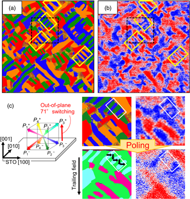
Fig. 5. (Color online) (a) Total PFM image of BFCMO thin film. The out-of-plane component directs downward of the thin film in the entire area. The in-plane component of each ferroelectric domain variant is colored as the inset. (b) MFM image of BFCMO thin film obtained in the same area as PFM. (c) Comparison of PFM and MFM images before and after the poling inside the area of broken boxes in (a) and (b). Total PFM images are colored as in the schematic illustration.
Download figure:
Standard image High-resolution image
We then demonstrated magnetization reversal by polarization switching for the BFCMO film. In Fig. 5(c), the top images are magnified views of the area inside the broken-lined box (∼1.5 × 1.5 μm2) in Figs. 5(a) or 5(b), and the bottom two figures are images obtained after the electric poling. It is clear from the total-PFM images that the out-of-plane polarization is switched from downward (P1−–P4−) to upward (P1+–P4+) in the entire poled region. There are only three domains, P1+(pink), P2+(light green) and P3+(light blue), and there is no P4+ (yellow) domain, which is unfavorable under a trailing field30,31) induced by the biased cantilever motion during the poling process. When we focused on the area inside the white box, the out-of-plane 71° polarization switching (i.e.: P2− to P2+ and P3− to P3+) occurred preserving the stripe domain pattern. Then, the stripe in magnetic domain structure remains through the poling process, but the color contrast in MFM is reversed, indicating that the out-of-plane magnetization switched via electric polarization. In contrast, outside the white box, 109° polarization switching (P1− to P2+ and P3− to P2+) and 180° one (e.g.; P1− to P3+ and P2− to P4+) as well as 71° one can be observed. This causes the magnetic domains changed destructively via the electric poling process, and the correlation between ferroelectric and ferromagnetic domains is unclear. These results agree with our previous report17) that 71° polarization switching without reconstruction of the stripe ferroelectric domain is a key of out-of-plane magnetization reversal phenomena in BFCO films.
In summary, the effect of the third element substitution on the B-site of BFCO thin film on the electrical and magnetic properties was investigated. The substitution of Mn or Sc was found to contribute to the stabilization of polarization switching by the poling with a cantilever. Magnetization reversal by application of an electric field in BFCMO is observed as well as in BFCO films. However, it is also found that substitution of Mn and Sc fragmented the electric and magnetic domains of BFCO film, leading to difficulties in observing the wide-range electric-magnetic correlation. Not only chemical substitution but also electrode configuration or method of electric field application should be improved in order to facilitate multiple magnetization reversals of BFCO.
Acknowledgments
This work was partially supported by Grants-in-Aid for Scientific Research, 17K14105, 18H05208 and 19H05625 from the Japan Society for the Promotion of Science (JSPS), a Grant-in-Aid for Challenging Research, Organization of Fundamental Research, Tokyo Institute of Technology, and by Project of Creation of Life Innovation Materials for Interdisciplinary and International Researcher Development of the Ministry of Education, Culture, Sports, Science and Technology (MEXT), Japan. The Mössbauer spectroscopic study was supported by the Nanotechnology Platform Program of MEXT, Japan. The PFM and MFM measurements were supported by the Suzukakedai Materials Analysis Division, Technical Department, Tokyo Institute of Technology.