
Abstract
RF reflectometry is a promising technique for spin qubit readout, suitable for large-scale integrated qubit systems by combination with multiplexing techniques and gate-based readout. However, one of the challenges in such systems would be that the accuracy of RF readout of individual qubits can be degraded by crosstalk among dense RF readout lines. In this study, we propose a mixed-mode RF reflectometry to reduce the effect of the crosstalk and verify its effectiveness by electromagnetic field simulations. The results of the simulations show the possibility of suppressing the influence of crosstalk by using mixed modes.
Export citation and abstract BibTeX RIS

Content from this work may be used under the terms of the Creative Commons Attribution 4.0 license. Any further distribution of this work must maintain attribution to the author(s) and the title of the work, journal citation and DOI.
1. Introduction
Practical quantum computation would require millions of qubits. 1,2) RF reflectometry is a promising technique to readout qubits in such a large-scale system, 3–14) thanks to its capability for signal multiplexing 3,15) and gate-based dispersive readout. 4,7) Reflectometry signals from the resonance circuits connected to qubits can be multiplexed in the frequency domain 4) as well as by phase encoding, using common readout circuitry outside the qubit chip. 16) However, RF lines for such readout may suffer from on-chip crosstalk when the density of the RF lines becomes higher. 17,18) The crosstalk will mix up signals, 19–21) resulting in unwanted applications of RF signals to unintended qubits and indistinguishable signals reflected from multiple qubits.
In this study, we propose a mixed-mode RF reflectometry to reduce crosstalk effects. 22–25) In the mixed mode, reflected signals are transmitted by differential and common modes of multiple transmission lines. By taking the coupling among transmission lines into account and superimposing the differential and common modes, we can obtain the reflection coefficient from a single line, hence reading out the individual qubit state, without crosstalk. We confirmed the effectiveness of the mixed mode in an electromagnetic field simulation software based on finite element method (Ansys HFSS). This paper is an extended version of Ref. 26 and includes a detailed explanation of mixed-mode transmission and simulation results. These results show crosstalk increases the impact of noise on reflectometry phase measurements, which can be suppressed by analyzing mixed-mode transmission. These considerations confirm the effectiveness of mixed-mode transmission in reducing the influence of crosstalk.
2. Theoretical background
Mixed mode transmits differential and common modes simultaneously. Advantages of mixed-mode transmission include improved immunity against noise and sensitivity to small signals in the differential mode. In the differential transmission, waves with the opposite polarities are passed through microstrip lines (MSLs), and the difference between the two signals is utilized. In the field of information and telecommunication, the common transmission is used only to measure the symmetry of the two transmission lines. In this paper, we use both of the two transmissions to obtain (ideal) single-ended S parameters without crosstalk influence  by converting the mixed-mode S parameters
  to single-ended S parameters. We note that the ideal single-ended S parameters
  cannot be calculated only from single-ended S parameters including crosstalk effect
  which are measured by standard RF reflectometry. In order to reduce the effect of crosstalk, the information on crosstalk coupling is indispensable.
For the S parameter conversion, we shall introduce the conversion matrix here. With a crosstalk influence, the conversion between mixed-mode S parameter ( ) and single-ended S parameter (
 ) is expressed with the modulation of the MSL characteristic impedance by crosstalk taken into account, by the following equations:
22)
) is expressed with the modulation of the MSL characteristic impedance by crosstalk taken into account, by the following equations:
22)


where  and
and  represent the crosstalk effects (
 and
and  are MSL characteristic impedances without crosstalk influence and differential- and common-mode characteristic impedances, respectively). In the absence of crosstalk,
  These Eqs. (1a
)–(1d
) are used later in this article to obtain single-ended S parameters to check the suppression of crosstalk influence by mixed-mode transmission.
These Eqs. (1a
)–(1d
) are used later in this article to obtain single-ended S parameters to check the suppression of crosstalk influence by mixed-mode transmission.
Based on the theoretical background described above, one can experimentally derive the single-ended S parameters with suppressed crosstalk effects from the following three steps. Firstly, we obtain characteristic impedances for differential and common modes ( and
and  ) by simulations or measurements.
22) These characteristic impedances are important parameters to obtain
) by simulations or measurements.
22) These characteristic impedances are important parameters to obtain  and
and  in Eqs. (1a
)–(1d
). Secondly, one measures the mixed-mode S parameters
in Eqs. (1a
)–(1d
). Secondly, one measures the mixed-mode S parameters  by RF reflectometry through a magic-T circuit.
27) Finally, the single-ended S parameters
by RF reflectometry through a magic-T circuit.
27) Finally, the single-ended S parameters  are calculated by substituting these parameters into Eqs. (1a)–(1d
).
are calculated by substituting these parameters into Eqs. (1a)–(1d
).
3. Simulation model
In what follows, we aim to simulate the influence of crosstalk on gate-based spin-qubit readout signals. We first quantify the effect of crosstalk for single-ended RF reflectometry, i.e., reflectometry without mixed-mode. We then demonstrate that signal degradation due to crosstalk will be suppressed in reflectometry with mixed-mode as theoretically discussed above. The simulation model used in this study is shown in Fig. 1(a). The model includes two adjacent MSLs. The parameter values used in the simulation are shown in Table I. Each MSL can be regarded as a transmission line for RF reflectometry to readout a qubit placed at the end of the line. Lumped resonance circuits consisting of inductance  capacitance
  and resistance
  are located at the end of line as a synthetic impedance for a qubit device and its readout LC resonator. In this analysis,
  nH,
nH,  fF, and
  MΩ.
13,28)
MΩ.
13,28)
 and
and  are determined based on typical values for real qubit systems; on the other hand, a small inductance is chosen for
  so that the resonance frequency is in the order of GHz. Such a relatively high resonance frequency for a spin qubit readout will be desirable in future integrated qubit systems where dense frequency multiplexing and wide bandwidth are needed at the same time. In this condition, the carrier signal is almost completely reflected with a phase shift [see Fig. 1(b)].
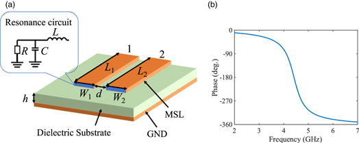
Fig. 1. (Color online) (a) Model for mixed-mode simulations. RF crosstalk can occur between the two MSLs. Each MSL is terminated with a resonance circuit. The other end is set as an RF port to readout the reflected RF signals. (b) The carrier frequency dependence of the reflection phase from a MSL terminated with a resonance circuit in (a). The resonance is observed around 4.5 GHz.
Download figure:
Standard image High-resolution imageTable I. Parameters for simulation of microstrip lines.
| Dielectric constant | 3.0 |
| Substrate thickness (h) | 0.128 mm |
| Distance between MSLs (d) | 0.001–1 mm |
| MSLs length (L1, L2) | 10 mm |
| MSLs width (W1, W2) | 0.3 mm |
| Inductor (L) | 10 nH |
| Capacitance (C) | 100, 101 fF |
| Resistance (R) | 1 MΩ |
To simulate the S parameters  and
and  of the two-MSL model, we utilized two types of RF ports: wave port and lumped port. The wave port is compatible with simulations where electromagnetic fields are spread under two MSLs, meaning that it can be used to analyze mixed modes containing differential and common modes. By mixed-mode analysis
22) the single line reflection coefficient without crosstalk can be obtained. On the other hand, a lumped port is used to calculate crosstalk effects in the MSLs. By comparing results for the two types of ports, we reveal the reduction of crosstalk effects in the RF reflectometry by mixed mode.
of the two-MSL model, we utilized two types of RF ports: wave port and lumped port. The wave port is compatible with simulations where electromagnetic fields are spread under two MSLs, meaning that it can be used to analyze mixed modes containing differential and common modes. By mixed-mode analysis
22) the single line reflection coefficient without crosstalk can be obtained. On the other hand, a lumped port is used to calculate crosstalk effects in the MSLs. By comparing results for the two types of ports, we reveal the reduction of crosstalk effects in the RF reflectometry by mixed mode.
4. Simulation result
To confirm the effectiveness of the mixed mode, we first simulated the amplitudes of 
 with and without the mixed mode (i.e.,
  and
and  ). Here,
  represents the reflection at port 1, and the reduction in its amplitude indicates crosstalk effects. We performed this analysis as a function of the inter-MSL distance
  with a carrier frequency of 4.5 GHz. In the simulation, w = 0.3 mm and d is changed between 1 μm and 1 mm. While d much smaller than 0.3 mm would be only meaningful when w is also reduced, we fix w to 0.3 mm in this work to keep the MSL characteristic impedance to 50 Ω.
As seen in Fig. 2(a), without mixed mode,  decreases as
  decreases, indicating the crosstalk effects. In contrast, as shown in Fig. 2(a), the mixed-mode analysis yields
  that is essentially independent of
  and almost equal to unity — an expected behavior without crosstalk. These results indicate an effectiveness of the mixed-mode detection.

Fig. 2. (Color online) (a) Reflection amplitude for port 1 in Fig. 1(a) with crosstalk when mixed mode is used (blue line) and unused (red line). (b) The absolute value of the difference in the amplitude of  without mixed-mode between
  fF and
  fF, as a function of MSL distance
  (c) The absolute value of the difference in the phase of
  without mixed mode between
  fF and
  fF, as a function of MSL distance
Download figure:
Standard image High-resolution imageIn some spin readout protocols such as quantum capacitance readout, RF reflectometry is used to read out a small capacitance change (∼1 fF) caused by the qubit state.
29) In the next simulation we simulate  for the two capacitance conditions, 100 fF and 101 fF, to emulate the qubit readout signal in such scenarios. Hereafter,
  (
( ) represents the reflection coefficient at
  fF (
fF ( fF). Figures 2(b) and 2(c) show the results of the shift in
  by the capacitance change as a function of
  As seen in the figures, the amplitude is affected by crosstalk; on the other hand, the phase is insensitive to
  These results indicate that phase readout is more robust against crosstalk than amplitude readout in our case, suggesting that it is more suitable for large-scale qubit systems with dense RF readout lines.
We simulated a spin readout measurement with crosstalk and revealed how mixed-mode detection can suppress the crosstalk influence. Here, we evaluate how this helps to readout the qubit state in the presence of noise.
30) To evaluate this effect, we assume a finite noise in the complex plane for the reflected signals and calculate a signal-to-noise ratio (SNR) dependence on the MSL distance  Here, we focus on the SNR for the RF phase, where we define the signal θ as the phase difference between the reflected signals for
  fF and
  fF, and the noise Φ as the phase broadening by noise
  [Fig. 3(a)].
  is a standard deviation defined by
  and is assumed to be ∼0.07,
31) where
and is assumed to be ∼0.07,
31) where  denotes the measurement outcome of
  for single-shot qubit readout in the presence of noise and
  denotes the statistical average (note that
  ). Φ is then given by
  where
where  is the reflection amplitude for
  fF (we neglect its change when
  is increased to
  fF). As shown in Fig. 2(c), θ does not change significantly by the crosstalk. On the other hand, since the absolute value of
  is reduced by crosstalk [Fig. 2(a)], Φ increases by crosstalk for the same amount of noise σ. Taking into these two contributions, crosstalk has a negative impact on SNR for RF phase readouts.

Fig. 3. (Color online) (a) The reflection coefficients  for different states in the presence of noise plotted in the IQ plane. In addition, θ represents the phase difference between
  and
and  σ represents the standard deviation in the
  measurement outcome, and Φ represents the phase spread due to noise. (b) Comparison of the change in θ and Φ (with and without mixed-mode analysis) as a function of MSL distance
Download figure:
Standard image High-resolution image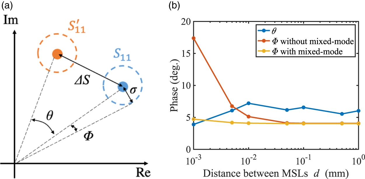
Figure 3(b) shows the calculated θ and Φ (with and without mixed mode analysis), where the model shown in Fig. 1 is used. Φ without mixed-mode detection is significantly affected as expected: it increases monotonically as the distance between MSLs becomes small. On the other hand, Φ with mixed-mode detection is almost independent of the distance. Comparing the Φ with and without the mixed-mode detection, the 14 degree increase of Φ for  mm is suppressed down to ∼1 degree. This simulation result shows the effectiveness of mixed-mode detection on the crosstalk effect between densely integrated MSLs.
5. Conclusions
In this study, we proposed a mixed-mode transmission to reduce the influence of crosstalk between close RF lines which are most likely employed in large-scale integrated qubit systems. First, we modeled a system for RF crosstalk by using an electromagnetic field simulator, which has two adjacent RF lines with readout resonators. Thereby, we performed simulations of the reflection of the system as a function of the distance between the two RF lines, with two different circuit parameters which correspond to different qubit states. The simulations show that although crosstalk increases as the distance between the two RF lines decreases, the reflection amplitudes obtained by using mixed-modes analysis are independent of the distance between MSLs. To confirm how this crosstalk affects spin readouts measurement, we simulated the impact of noise for RF phase measurement. We confirmed in the simulation that the mixed-mode detection can suppress the influence of crosstalk on phase noise, with Φ reduced from 14 degrees to 1 degree in some cases. We anticipate that this technique will be helpful for the realization of large-scale qubit systems.
Acknowledgments
This work was supported by MEXT Quantum Leap Flagship Program (MEXT QLEAP) Grant No. JPMXS0118069228, JST Moonshot R&D Grant No. JPMJMS2065, JST CREST (JPMJCR1675), JST PRESTO (JPMJPR21BA), and JSPS KAKENHI (20H00237, 20K15114, 21K14485).