
Abstract
MnSi1.7 nanosheet bundles with an improved homogeneous composition were synthesized by annealing from CaSi2 crystal powders with MnCl2 in molten salt. The MnSi and Si phases were formed at the initial stage of the synthesis with an inhomogeneous Mn distribution within the nanosheet bundles. Subsequently, the phases were transformed into MnSi1.7 with an improved homogeneous Mn distribution within them for 10 h annealing in the molten salt. The formation of multiple Mn-silicide phases and remarkable improvement in the structural homogeneity of the MnSi1.7 nanosheet bundles were discussed in terms of the reactions of Mn or Si with chloride compounds, decomposition of chlorides at elevated temperatures, phase selection of multiple silicide phases, shrinkage of the volume from Si to MnSi1.7, and dominant diffusion species. Multiple growth variants of the MnSi1.7 domains were stacked in the nanosheets. For comparison, the growth in a deliquescent environment realized by NH4Cl addition was examined.
Export citation and abstract BibTeX RIS
1. Introduction
Low-dimensional materials have attracted much interest because of their enhanced or modified properties compared with those of the bulk materials. 1,2) A nanosheet bundle is an important structure for technological applications, 3) especially in large-volume and large-area devices, such as thermoelectric generators and thermophotovoltaic batteries.
Higher manganese silicides (HMS) with a composition near MnSi1.7 are semiconducting silicides with a direct band gap of approximately 0.7 eV. The HMS are stable at high temperatures, 4) and are considered to be appropriate semiconducting materials for infrared photovoltaic devices (e.g. thermophotovoltaic batteries). 5) In addition, the HMS are promising thermoelectric materials. 6,7) Several possible structures called MnSi1.7 exist, which are superstructures of a tetragonal subcell with c ∼ 0.437 nm. These structures are Mn4Si7, Mn11Si19, Mn15Si26, Mn26Si45, and Mn27Si47, which have a lattice constant a of approximately 0.553 nm and an unusually long c-axis of up to approximately 10 nm. For synthesizing MnSi1.7, MnCl2 is used as the Mn source material. To date, MnSi1.7 layers, powders, and nanowire arrays have been synthesized. 8–10)
On the other hand, low-dimensional, quantum-confined systems were reported to exhibit sharp and nearly dispersionless bands. The appropriate size tuning to place these bands near the Fermi level could enable a marked increase in thermopower 11) that modifies or improves the optoelectronic properties. It is expected that the artificial two-dimensional MnSi1.7 silicide nanosheet bundles would modify the electronic structure and phonon characteristics of silicide, thereby improving the infrared photovoltaic and thermoelectric properties. The synthesis of silicide nanosheet bundles has been attempted via Ca extraction from CaSi2 powder. However, silicide nanosheet bundles are difficult to synthesize using these methods, owing to the instability and thermal decomposition of the source materials. The development and difficulty of forming silicide nanosheets and their bundles are discussed below.
When the CaSi2 crystal is used as a template to synthesize the bundle structure, the crystal shows tr6 and tr3 modifications of CaSi2, which differ by their stacking sequence or equivalently by the rotation of subsequent silicon double layers. 12) The Si formation by extracting Ca from CaSi2 crystals via a thermal treatment with metal chlorides using SnCl2, SbCl3, BiCl3, PbCl2, or HgCl2 has been reported. 13) Furthermore, the Si formation using CaSi2 and Cl2, as well as the reactions of CuCl2 and Si, and "active silicon" containing copper together with silver, zinc, and aluminum, have been reported. 14) However, details of the structural properties of the treated nanosheets have not been clarified. Moreover, the synthesis of siloxene and its derivatives using electrochemical methods in solutions has been reported. 12,15–17) The formation of Si nanosheet bundles from CaSi2 crystals via a chemical treatment using inositol hexakisphosphate (IP6) (C6H18O24P6) solution has been reported. 18)
Si-based nanosheet bundles were synthesized by extracting Ca from CaSi2 powders via a solid-state exfoliation reaction using chlorides. 19–22) In these reactions, metallic atoms were not incorporated into the Si nanosheets; however, silicide particles were formed. In the synthesis technique using CrCl2 as the Ca extraction agent, Si nanosheets were formed, and Cr atoms were not incorporated into the Si nanosheets. 23) Additionally, silicon-based nanosheets were synthesized using CaSi2 in a CuCl2 aqueous solution, SnCl2 ethanol solution, or SnCl2 with LiCl/KCl molten salt. 24) Notably, metal nanoparticles were formed between the nanosheets, and the metals did not diffuse into the Si nanosheets. Moreover, Si-based nanosheet bundles using CaSi2 crystals were synthesized by thermal annealing in metal chloride vapors, including FeCl2, FeCl3, deliquescent MgCl2, and NH4Cl. 25) Recently, Mg2Si/Si nanocomposites consisting of Si nanosheets and Mg2Si deposits on a Si nanosheet were synthesized via thermal annealing in MgCl2 vapor. 26) Subsequently, Mg2Si nanosheet bundles were synthesized by thermal annealing under MgCl2/Mg mixed vapors. 27) Thus, adding an excess Mg source is important to obtain structurally homogeneous Mg2Si nanosheet bundles.
In this study, the MnSi1.7 nanosheet bundles were synthesized from CaSi2 crystal powders using MnCl2 and the growth phenomena of the nanosheet bundles was examined under various experimental conditions, especially in molten salt conditions. In addition, the structural properties of the nanosheet bundles were characterized. The growth evolution of the MnSi1.7 nanosheet bundles with improved structural homogeneity was examined. Furthermore, MnSi1.7 nanosheet bundles were also synthesized by thermal annealing under MnCl2/NH4Cl vapor for comparative evaluation.
2. Experimental methods
Commercially available CaSi2 crystal powder (99% pure, powder with a typical diameter of approximately 10–100 μm in size, Kojundo Chemical Laboratory Co., Ltd.) was used as a template material. CaSi2 and MnCl2 powders (99.9%up pure, powder, Kojundo Chemical Laboratory Co., Ltd.) with a molar ratio of CaSi2:MnCl2 = 1:1 were placed in a quartz container inside a sealed stainless-steel cell under an Ar atmosphere with less than 0.1% oxygen. Scanning electron microscopy (SEM) images of the source powders, used in this study, are shown in Appendix A. The powders were annealed according to the temperature profile, shown in Fig. 1(a). At the end of the annealing period, the heaters were turned off, and the cells were naturally cooled. The molten salt synthesis was carried out at 800 °C for 10 h. The temperature profile of the "Sample 3" is shown in Fig. 1(a), wherein the melting temperatures of MnCl2 and CaCl2 are 654 °C and 772 °C, respectively. In this case, the annealing temperature of 800 °C is higher than the melting temperatures. To examine the growth evolution, the products were synthesized at 600 °C and 800 °C during an increase in the cell temperature by heating with a rate of 13 °C min−1 at the initial stage of the synthesis, shown as "Samples 1 and 2" in Fig. 1(a), respectively. The nanosheet formation reactions had already begun during the rise in the cell temperature. The heaters were immediately turned off when the cell temperature reached 600 °C and 800 °C. These synthesis conditions are noted here as the annealing temperatures of 600 °C and 800 °C for "0 h" thermal annealing time, respectively. Evidently, the annealing temperature of 600 °C was lower than the melting temperatures of MnCl2 and CaCl2. The nanosheets were synthesized at 600 °C for 10 h (Sample 5). After the thermal annealing process, the prepared nanosheets were washed in deionized water and ethanol several times for a few minutes to remove the residual chloride compounds. For comparison, a mixed-source powder with a molar ratio of CaSi2:MnCl2:NH4Cl = 1:1:2 was annealed at a thermal annealing temperature of 600 °C for 10 h (Sample 6), to examine the growth feature in the deliquescent environment, mentioned later.
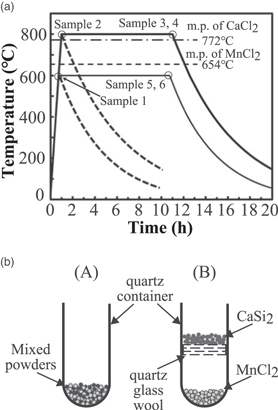
Fig. 1. "Black and white" (a) Temperature profile of the container during the growth and (b) source material configurations (A) and (B).
Download figure:
Standard image High-resolution imageTwo types of source-material configurations were employed, as shown in Fig. 1(b). In the source-material configuration (A), all the source powders were mixed and placed at the bottom of the quartz container. In contrast, MnCl2 was placed at the bottom of the quartz container, and CaSi2 was placed separately using quartz glass wool in the source-material configuration (B). At an annealing temperature of 600 °C, which is lower than the chloride melting temperatures, the CaSi2 powders were exposed to the MnCl2 vapor and vapor-phase growth occurred for both source-material configurations (A) and (B) (Sample 4). Meanwhile, for the synthesis at 800 °C, which is higher than the chloride melting temperatures, the CaSi2 powders were immersed in the chloride molten salt for the source-material configurations (A) resulting in the growth of liquid molten salt. Note that the vapor-phase growth occurs for the source-material configuration (B) at the annealing temperature of 800 °C. Most of the experiments, in this study, were conducted using the source-material configuration (A). Table I lists the series of the nanosheet bundles, prepared under the synthesis conditions, as mentioned previously.
Table I. A series of Mn-silicide nanosheet bundles synthesized from CaSi2 crystal powders by thermal annealing with MnCl2.
| Sample | Temperature (°C)/time (h) | Source material configuration | Additional compound | Products |
|---|---|---|---|---|
| Sample 1 | 600/0 | (A) | — | CaSi2, Si, MnSi |
| Sample 2 | 800/0 | (A) | — | Si, MnSi, (MnSi1.7) |
| Sample 3 | 800/10 | (A) | — | MnSi1.7, (MnSi) |
| Sample 4 | 800/10 | (B) | — | Si, MnSi, |
| Sample 5 | 600/10 | (A) | — | Si, MnSi, MnSi1.7 |
| Sample 6 | 600/10 | (A) | NH4Cl | Si, MnSi1.7 |
The morphological and structural properties of the nanosheet bundles were characterized using field-emission scanning electron microscopy with energy dispersion spectroscopy (EDS), conventional transmission electron microscopy (TEM), high-resolution TEM (HRTEM) with fast Fourier transform (FFT), and scanning transmission electron microscopy with EDS. For TEM sample preparation, the products were dispersed in a small amount of ethanol, transferred onto a lacey-carbon-coated copper grid, and dried.
3. Results and discussion
3.1. Results
The MnSi1.7 nanosheet bundle with improved structural homogeneity was synthesized by thermal annealing at 800 °C for 10 h (Sample 3). To examine the growth evolution of the nanosheets, the structural characterization of the nanosheets at 600 °C for 0 h (Sample 1) and 800 °C for 0 h (Sample 2) was performed. In Sample 1, the CaSi2 phase remained, and a few Si and MnSi phases were formed, as shown in Fig. 2(a). In Sample 2, the CaSi2 peaks disappeared, and the major products were also Si and MnSi phases [Fig. 2(b)]. When the annealing time was increased to 10 h (Sample 3), the intensities of the MnSi1.7 peaks increased, even though the small MnSi and Si peaks remained [Fig. 2(c)]. In contrast, the Si peaks were dominant in the XRD pattern of Sample 4 [Fig. 2(d)], which was synthesized at 800 °C for 10 h by using the source-material configuration (B). In this case, the MnSi1.7 and MnSi peaks were almost invisible (Sample 4). The geometric configurations of the source materials affect the gas flow-path in the vapor phase. If the configuration is not appropriate, the Mn deposition on the Si nanosheets would be suppressed. The results indicate the growth of MnSi1.7 with improved homogeneity in Sample 3 because of the high temperature and liquid molten salt environment.

Fig. 2. "Black and white" XRD patterns of the powders annealed at (a) 600 °C for 0 h (Sample 1), (b) 800 °C for 0 h (Sample 2), (c) 800 °C for 10 h with the source material configuration (A) (Sample 3), and (d) 800 °C for 10 h with the source material configuration (B) (Sample 4).
Download figure:
Standard image High-resolution imageThe effect of additional 10 h annealing at 600 °C was compared with the structural characterization of the vapor-phase-synthesized silicide nanosheet bundles. When the annealing time is increased to 10 h at this temperature, the CaSi2 peaks disappeared, and the intensity of Si peaks increased (Sample 5), as shown in Fig. 3(b). However, the compositional inhomogeneity remained in the nanosheet bundles caused by the additional formation of Si and MnSi under the vapor-phase synthesis condition when compared with those of Sample 1 (600 °C, 0 h). In addition, peaks of the MnSi phase did not appear if NH4Cl was added (Sample 6), when compared with those of Sample 5 (600 °C, 10 h without NH4Cl), as shown in Fig. 3(c). The effect of NH4Cl on the thermal reaction of CaSi2 with MnCl2 will be discussed later.

Fig. 3. "Black and white" XRD patterns of the powders annealed at (a) 600 °C for 0 h (Sample 1), (b) 600 °C for 10 h (Sample 5), and (c) 600 °C for 10 h with NH4Cl (Sample 6).
Download figure:
Standard image High-resolution imageAll the products were synthesized in powder form (Fig. 4), which maintained the dimensions of the original CaSi2 powders reported in a literature. 28) The low magnification SEM images and EDS mappings of Samples 1, 2, and 3 with the source-material configuration (A) are shown in Figs. 4(a)–4(c), respectively. In these cases, Ca extraction was successfully obtained with the increasing temperature and annealing time. The observed sheet thickness of the bundles, annealed at 600 °C for 0 h (Sample 1), was approximately a few micrometers in appearance. The bundles became thinner to approximately sub-micrometers in appearance when synthesized at 800 °C for 0 h and 10 h (Samples 2 and 3). The sheets were alternately stacked with small void spaces to form a bundle. The sheets observed in the image were easily exfoliated and divided into to further thinner nanosheets, as shown later in Fig. 5. Mn atoms started to deposit on the nanosheet bundles synthesized by thermal annealing at 600 °C for 0 h (Sample 1). The Mn atoms were inhomogeneously distributed throughout the nanosheet bundles synthesized by thermal annealing at 800 °C for 0 h (Sample 2), as shown in the EDS mappings of the bundle in Fig. 4(b). The homogeneity of the Mn atom distribution is improved by thermal annealing at 800 °C for 10 h [Sample 3; Fig. 4(c)]. The images in Figs. 4(b) and 4(c) and XRD patterns in Figs. 2(b) and 2(c) suggest that MnSi and Si phases are formed at the initial stage of the synthesis with an inhomogeneous Mn distribution within the nanosheet bundles. Further, the phases are transformed into MnSi1.7 nanosheet bundles with improved homogeneous Mn distribution after 10 h annealing in the molten salt.
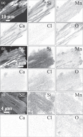
Fig. 4. "Black and white" SEM image and corresponding EDS mappings of the powders annealed at (a) 600 °C for 0 h (Sample 1), (b) 800 °C for 0 h (Sample 2), and (c) 800 °C for 10 h (Sample 3) with the source material configuration (A).
Download figure:
Standard image High-resolution image
Fig. 5. "Black and white" (a) Plan-view image, (b) cross-sectional view TEM image, and (c) plan-view HRTEM image and its FFT pattern of a piece of the MnSi1.7 nanosheet bundle annealed at 800 °C for 10 h (Sample 3).
Download figure:
Standard image High-resolution imageThe detailed fine structures of the exfoliated nanosheets were examined using TEM. Plan-view, cross-sectional view, and enlarged plan-view TEM images of pieces of the nanosheet, annealed at 800 °C for 10 h (Sample 3), are shown in Figs. 5(a)–5(c), respectively. The plan-view image shows that relatively uniform sheets were exfoliated, including domains with diameters of approximately 100 nm. The cross-sectional TEM image shows nanosheets with a thickness of several tens of nanometers, and up to approximately 200 nm are stacked with small void spaces to form a bundle. The nanosheet had a layered structure over a wide range of areas through the nanosheet, and stepped structures were observed near the edge of the nanosheets. A stacked structure, consisting of the nanosheets, was also observed in Fig. 5(c). In the image, broad, wavy, and moiré-like fringes were observed, and the features of the fringes are explained as follows.
29) Spots, which occur in the diffraction pattern where two satellite sequences meet or overlap, can also be used to make an image. The fringes are more widely spaced, and perpendicular to the segment  connecting the two interfering satellite spots. The distance is inversely proportional to
  The direction of
  is highly sensitive to slight changes in the direction of the satellite sequence. These moiré-like fringes provide a map of the vector
  and thus of the spacing and orientation anomalies.
29)
and thus of the spacing and orientation anomalies.
29)
The long-range periodic structure of MnSi1.7 was confirmed by HRTEM images and their FFT patterns (Fig. 6). Distinct symmetrical FFT patterns were obtained for the nanosheets, synthesized by the thermal annealing at 800 °C for 10 h (Sample 3). The basic spots are marked with circles. 30) The FFT spots, indexed using subcell notation, correspond to the sections of the reciprocal lattice with zone axes [210] and [110] of the basic structures, respectively.

Fig. 6. "Black and white" HRTEM images with the corresponding FFT patterns of a part of the MnSi1.7 nanosheet annealed at 800 °C for 10 h (Sample 3) observed along the (a) [210] and (b) [110] directions.
Download figure:
Standard image High-resolution imageThe distinct FFT patterns are a consequence and signature of the mismatched sublattices of the intricate MnSi1.7 Nowotny chimney ladder structures. Each bright "main" spot, associated with the Mn sublattices, is superimposed with a series of more closely spaced "satellite" reciprocal spots associated with a larger Si sublattice spacing. 29,31) In the FFT patterns, differences among several HMS structures cause additional weak spots in the patterns for the special zone axis. 32) Furthermore, the positions of some spots slightly differed slightly for different HMS phases. 32) However, because of the limited spatial resolution of the TEM images of MnSi1.7 in Fig. 6, identifying the particular MnSi1.7 phase is difficult.
The HRTEM image and corresponding FFT pattern of Sample 3 are shown in Fig. 7. The crystalline direction and plane of the layers were denoted using a MnSi1.7 subcell crystalline lattice. As previously reported, the crystallographic orientation relationship between MnSi1.7 and Si is [111] MnSi1.7 subcell//[111]Si and ![$[\bar{1}10]\,$](https://content.cld.iop.org/journals/1347-4065/62/SD/SD1021/revision2/jjapacaeb1ieqn5.gif) MnSi1.7 subcell//
MnSi1.7 subcell// ![$[\bar{1}10]\,$](https://content.cld.iop.org/journals/1347-4065/62/SD/SD1021/revision2/jjapacaeb1ieqn6.gif) Si, using the MnSi1.7 subcell notation.
33) Considering that the surface of the Si nanosheet formed from CaSi2 crystals is Si(111),
18) three types of variants possibly exist in the sheet because of the three-fold symmetry of the Si(111) surface. These variants are rotated by 120° with respect to each other along the growth direction.
33) For the tetragonal MnSi1.7 subcell crystalline lattice, the [111] direction was nearly parallel and inclined by just 1.5° with respect to the direction perpendicular to the (332) plane. Using a conventional notation, the predominant epitaxial relationship between MnSi1.7 and Si is given by (332), [110]MnSi1.7//(111), [110]Si, where the (332) MnSi1.7 plane is equivalent to (3322) and (3330) for Mn11Si19 and Mn15Si26, respectively.
33) The HRTEM image in Fig. 7(a) was obtained from the nanosheet, which was observed along the direction tilted by ∼20° from the [111]MnSi1.7 subcell direction roughly toward the [100] subcell direction. By tilting the observation direction, the lattice fringes of {210} and {122} appear. In addition, two stacked domains with moiré-like fringes, rotating each other at approximately 120°, were observed. In the FFT pattern, additional unmarked spots from domains A and B, and others were also observed. Some spots appeared because of the satellite sequences of other further inclined domains.
Si, using the MnSi1.7 subcell notation.
33) Considering that the surface of the Si nanosheet formed from CaSi2 crystals is Si(111),
18) three types of variants possibly exist in the sheet because of the three-fold symmetry of the Si(111) surface. These variants are rotated by 120° with respect to each other along the growth direction.
33) For the tetragonal MnSi1.7 subcell crystalline lattice, the [111] direction was nearly parallel and inclined by just 1.5° with respect to the direction perpendicular to the (332) plane. Using a conventional notation, the predominant epitaxial relationship between MnSi1.7 and Si is given by (332), [110]MnSi1.7//(111), [110]Si, where the (332) MnSi1.7 plane is equivalent to (3322) and (3330) for Mn11Si19 and Mn15Si26, respectively.
33) The HRTEM image in Fig. 7(a) was obtained from the nanosheet, which was observed along the direction tilted by ∼20° from the [111]MnSi1.7 subcell direction roughly toward the [100] subcell direction. By tilting the observation direction, the lattice fringes of {210} and {122} appear. In addition, two stacked domains with moiré-like fringes, rotating each other at approximately 120°, were observed. In the FFT pattern, additional unmarked spots from domains A and B, and others were also observed. Some spots appeared because of the satellite sequences of other further inclined domains.
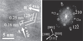
Fig. 7. "Black and white" HRTEM image with the corresponding FFT pattern of a part of the MnSi1.7 nanosheet annealed at 800 °C for 10 h (Sample 3) observed along the direction titled by ∼20° from the [111]MnSi1.7 subcell direction roughly to [100] subcell direction. The FFT spots, which belong to variants A and B, are marked by circles and squares, respectively. A schematic illustration of the crystallographic orientations of the MnSi1.7 subcell in the variant A is also shown. The indexes are shown in the subcell notation. Unmarked additional spots from domains A and B, and others are also observed.
Download figure:
Standard image High-resolution image3.2. Discussion
MnSi1.7 nanosheet bundles were successfully synthesized from CaSi2 crystal powders with improved homogeneous Mn distribution by thermal annealing with MnCl2 in a molten salt liquid-phase environment. However, nanosheet bundles with inhomogeneous Mn distribution through the powders and the existence of Si were also observed at the initial stage of the synthesis procedure. The major products of each sample are listed in Table I. The synthesis mechanism of Mn silicide and its nanosheet structure is as follows.
As the cell temperature is gradually increased from the room temperature [Fig. 1(a)], MnCl2 evaporates during the initial thermal annealing stage. For example, the vapor pressures are 0.21 Pa at 527 °C and 6.3 Pa at 627 °C, 34) providing enough impingement rate for deposition. The CaSi2 powders are exposed only to the MnCl2 vapor, when the cell temperature is lower than the melting temperature of MnCl2 of 654 °C. CaCl2 forms via the vapor-phase reaction of evaporated MnCl2 with CaSi2 powders and also possibly a solid-phase reaction between them where these powders are attached to each other. Based on the enthalpy of the formation of CaSi2 (−12.0 kcal/g-atom), MnCl2 (−38.4 kcal/g-atom), and CaCl2 (−63.4 kcal/g-atom), 35) the formation of CaCl2 is thermodynamically favored as compared to that of CaSi2, which would be a driving force for the reaction. 19) The formation of CaCl2 was confirmed in the products before washing, as discussed in Appendix A. The Mn atoms were inhomogeneously deposited on the nanosheet bundles. The MnSi phase, rather than the MnSi1.7 phase, was formed first, and the Si remained as nanosheets. The source powders were sealed under Ar at 1 atm (∼1 × 10⁵ Pa) and the total pressure inside the container at the annealing temperature was ∼3 × 10⁵ Pa. Thus, the mean free path of the molecules in the vapor is of the order of 10–100 nm. 36) At the synthesis temperature of 600 °C, the partial vapor pressure of MnCl2 is approximately 1 Pa. 34) Although the mean free path of the molecules in the vapor is too short, the Mn atoms would be preferentially deposited on the Si nanosheet surface facing and nearly attached to the MnCl2 source powders. The CaSi2 and MnCl2 source powders were randomly mixed. For MnCl2, the following reactions were considered for the MnSi growth: 37)


In addition, MnSi deposition is also expected as

It is reasonable to consider that Mn atoms are deposited and MnSi is formed. The deposited MnSi could further react with Si at elevated temperature, leading to the formation of MnSi1.7. On the other hand, it was reported that Mn atoms were deposited on Si substrates, the MnSi and MnSi1.7 phases were formed at the synthesis temperature of approximately 500 °C–600 °C using MnCl2 as a source material. The result indicates that Mn atoms were practically deposited on Si around the vapor-phase synthesis temperature using MnCl2. 8) In addition, Cl atoms are adsorbed just on Si surfaces and the Si surfaces are terminated by the chlorine. It was observed that chlorine or silicon dichloride were desorbed approximately at 600 °C and higher from Si surfaces. 38) According to literatures, 8,38) the sticking rate of Cl atoms is considered to be lower than that of Mn atoms. Chlorine or chloride molecules would wrap around the powders to react with CaSi2 to form CaCl2 and Si nanosheets around the other side of the nanosheets or bundles under the vapor-phase condition with those relatively shorter mean free path. In contrast, Mn atoms are deposited on the CaSi2 or Si nanosheet surfaces, directly facing to the MnCl2 powders. Thus, the inhomogeneous distribution of Mn in the nanosheet bundle was observed, despite the long annealing time of 10 h at 600 °C (Sample 5), as shown in Fig. 3(b), which revealed the additional formation of Si and MnSi. Although Mn atoms were the dominant diffusion species for the practical case of Mn deposition on Si using MnCl2, 8) Mn diffusion into the Si nanosheets was suppressed, owing to the existence of the void space between the nanosheets.
Because the cell temperature is higher than the melting temperature of MnCl2 (654 °C) and CaCl2 (772 °C), the liquid-phase growth took place for the source-material configuration (A). The MnCl2 molten salt was followed by the formation of MnCl2–CaCl2 eutectic molten salts because CaCl2 was formed as a byproduct of the reaction between CaSi2 and MnCl2. Although CaSi2 was consumed by increasing the annealing temperature to 800 °C, Mn distribution remained inhomogeneous for an annealing time of 0 h [Sample 2, Fig. 4(b)]. However, a drastic improvement in the Mn distribution was observed with an annealing time of 10 h for source-material configuration (A) (Sample 3). Note that, using the material configuration (B) at a temperature of 800 °C for 10 h (Sample 4), the Si formation was dominantly observed because the Mn atoms would be evaporated again from the nanosheets without capping materials in this configuration to the vapor-phase.
The results indicate that the homogeneity of the Mn distribution in Mn-silicide nanosheet bundles was remarkably improved by long annealing in the molten salt (Figs. 2 and 4). The structures of molten MnCl2 39) and CaCl2 have been reported previously. 40) One possible arrangement of ions in molten MnCl2 is the ionic orientation of a 180° corner share for each MnCl4 tetrahedron around the shared Cl atoms. It is reasonable to consider that the interactions between Mn2+ and Cl− ions are not strong. 39) The Mn2+ ions were densely and homogeneously distributed in the molten salt. The Mn atoms might be homogeneously incorporated and diffused anywhere into the Si nanosheets from the liquid molten salt. Although Mn atoms were inhomogeneously distributed during the initial stage of the vapor-phase synthesis procedure, the existence of the MnSi was suppressed, and MnSi1.7 was dominantly formed and further homogeneously synthesized with Si consumption through the nanosheet bundles under the liquid molten salt environment. MnSi might be decomposed and redistributed to form MnSi1.7 through the nanosheet bundles in the molten salt. Hence, the following two possibilities are considered: (1) the interdiffusion of Mn atoms becomes more active at the interface between the nanosheets and the liquid molten salt, compared with the surface of the nanosheets under a vapor atmosphere. (2) Mn atoms are excessively deposited to form MnSi under non-equilibrium conditions, which is dominated at the initial stage of the synthesis procedure. These atoms would be dissolved into the liquid molten salt. Then, Mn atoms are deposited again on the nanosheet to form MnSi1.7, as an equilibrium reaction facilitated by the molten salt as a pass of the Mn redistribution. These speculations agree with the discussion highlighted in a literature, as "The CaCl2 and NaCl eutectic mixture melt was speculated to promote the uniform formation of Pt2Ca nanoparticles." 41) The phenomenon of the uniform formation in the molten salts, revealed in the literature, was also observed in our experimental results, although the material systems vary. To obtain structurally homogeneous nanosheet bundles, bundles in the molten salt should be synthesized for liquid-phase synthesis. During the thermal annealing treatment at 800 °C for 0 and 10 h, the liquid phase contained MnCl2–CaCl2 (primarily CaCl2) molten salts, because CaCl2 is a byproduct of the reaction between CaSi2 and MnCl2. One of the advantages of forming a CaCl2-based molten salt is that it dissolves the Mn and/or Si in the molten salt. 42,43) CaCl2 is a byproduct of a series of the reactions; however, it plays an important role in the facile synthesis of silicides, because MnSi alloy was prepared from SiO2–MnO2 in CaCl2–NaCl molten salt. 44) Further investigations will be required to clarify the role of the MnCl2–CaCl2 (primarily CaCl2) molten salt. Thus, the reaction between MnSi and molten CaCl2 was examined at an annealing temperature of 800 °C for 10 h, as shown in Appendix B. Evidently, the MnSi surface was damaged and etched by CaCl2 molten salts. The results indicate that morphological modification was observed before and after annealing, implying that Mn and Si atoms were more mobile on the MnSi surfaces or removed from the surface in the molten salt. The results support the above speculations and show that CaCl2 molten salt is useful for dissolving or decomposing MnSi, which should be avoided, as well as the formation of MnSi1.7, by the interdiffusion between MnSi and Si at elevated temperatures.
Previously, the formation of Si nanosheets by Ca extraction from CaSi2 crystals via thermal annealing with chlorides and metal chlorides has been investigated. Although metal chlorides, such as SnCl2, SbCl3, BiCl3, PbCl2, and HgCl2 13) were used as source materials, metal deposition or the incorporation of metals into Si nanosheets was rarely reported. The details of the structural properties of the treated nanosheets have not yet been clarified. It was reported that fully oxidized silicon nanosheets were synthesized in a CuCl2 aqueous solution at room temperature, whereas partially oxidized silicon nanosheets were synthesized in SnCl2 ethanol solution at 60 °C. Hardly oxidized silicon nanosheets were synthesized in LiCl–KCl molten salt at 400 °C. The metal nanoparticles in the silicon nanosheets were removed by rinsing the as-prepared silicon nanosheets with a solution. 24) Note that metal nanoparticles were formed between the nanosheets, and metal diffusion into the Si nanosheets has not been reported. In addition, Si-based nanocomposites derived from CaSi2 were synthesized via a solid-state reaction using NiCl2, FeCl2, MnCl2, and TaCl5. 19–22) In a series of the experiments, Ni or Fe silicide particles were formed. However, Ni, Fe, and Ta atoms were not incorporated into the Si nanosheets, and silicide nanosheet formation was not reported. For Mn-silicides, detailed nanostructures have not been reported. When CrCl2 was used as a Ca extraction agent, Cr atoms were not incorporated into the Si nanosheets, and CrSi2 nanosheets were not formed. 23) Moreover, Si-based nanosheet bundles using CaSi2 crystals as a template were synthesized by thermal treatment of metal chloride vapors, including FeCl2, FeCl3, deliquescent MgCl2, and NH4Cl. 25) Mg2Si/Si nanocomposites comprising Si nanosheet bundles and Mg2Si deposits have been synthesized; however, homogeneous single-phase Mg2Si nanosheets have not been formed using MgCl2, which was carefully stored to avoid deliquescence. 26) The Mg2Si nanosheet bundles were synthesized by annealing in MgCl2/Mg mixed vapor. 27) An additional Mg source was required to form homogeneous single-phase Mg2Si nanosheet bundles.
The difficulty of silicide nanosheet formation was discussed based on the assumption that metal chlorides are decomposed, and HCl, Cl2, and their oxides or hydroxides are formed. The formation is caused by the reactions of metal chlorides with residual moisture and/or oxygen due to thermal instability and deliquescence of the chloride compounds, as reported in a literature. 25) The HCl molecules are transported to the CaSi2 crystals to extract Ca atoms. The excess HCl itself etches the silicide nanosheets, and removes the metal atoms from the nanosheet to form Si nanosheets. In addition, once the compounds are formed, it becomes difficult to form silicides via reactions with Si-nanosheets. A detailed discussion has been reported in the literature. 25) Thus, this nanosheet formation model was proposed to explain the dependence of the structural and morphological properties of Si-based nanosheets on the thermal annealing conditions, including the reactant.
For FeCl2 and MgCl2, the decomposition of the chloride compounds by reaction with residual moisture at an elevated temperature was discussed for the Si nanosheet bundle synthesis. 25) However, to the best of our knowledge, the formation of HCl via the thermal decomposition of MnCl2 has rarely been reported. The thermal stability and thermodynamics of MnCl2 45) and the decomposition behavior of several hydrous transitions have been reported. 46) In addition, a differential thermal analysis of MnCl2·4H2O was performed. 47) The formation of HCl is less pronounced because of the relatively more stable Mn chloride compared to other chlorides, such as MgCl2 or FeCl2 which chlorides causes the formation of their oxides or hydroxides by reactions with residual moisture and/or oxygen. 25) The incorporation of Mn into the Si nanosheets originating from CaSi2 crystals would not be suppressed compared with the metal incorporation of Mg or Fe into the Si nanosheets. In the past, MnSi1.7 with a variety of morphologies, namely, MnSi1.7 bulk crystals, 48) layers, 8) powders, 9) and nanowire arrays 10) have been synthesized using MnCl2 as a Mn-source material. Furthermore, Si nanowires were also synthesized using MnCl2. In this case, MnCl2, MnSi1.7, or other Mn-based compounds acted as catalyst for the growth of Si nanowires when the excess Si atoms were supplied. 10,49,50)
It is interesting to compare the results with and without NH4Cl source for the nanosheets synthesized at 600 °C for 10 h (Samples 5 and 6). When NH4Cl was used as the source material, the dissociation of NH4Cl provided HCl formation, similar to the case of using deliquescent chloride; the HCl molecules were significantly transported to the CaSi2 crystals at elevated temperatures. The discussion is consistent with the cases of the metal incorporation of Mg or Fe into Si nanosheets in the vapor phase. 25) MnSi formation was observed in nanosheet bundles, synthesized without NH4Cl. In contrast, MnSi formation was suppressed by the addition of NH4Cl (Fig. 3). Therefore, the HCl provided by NH4Cl was considered to remove the Mn atoms or suppress the additional Mn deposition in the vapor-phase synthesis environment.
The phase selection of Mn-silicide formation has been extensively discussed. The Mn–Si phase diagram indicates the presence of Mn6Si, Mn3Si, Mn5Si2, Mn5Si3, MnSi, and MnSi1.7. 51) For the Mn–Si diffusion couple, the first nucleating phase was predicted to be Mn5Si3. 52) In contrast, three phases, i.e. Mn3Si, Mn5Si3, and MnSi, were formed through a layered growth process. The formation sequence for these silicides was Mn3Si, MnSi, and Mn5Si3. 53) Unusual phenomena of coexistence of these three phases and simultaneous growth of two phases (MnSi and Mn5Si3) were also observed. 53) The phase formation depended not only on the equilibrium formation energy, but also on the interfacial composition, and lattice mismatch between the silicide phase and Si matrix. 54) Furthermore, the growth strongly depended on the boundary conditions, in addition to the free energy of formation. 54) The selective growth of a particular phase was reported to be triggered mainly by a specific interface composition and governed by the diffusion flux at the interface. 55) In this study, MnSi and MnSi1.7 phases were formed during the silicidation reaction between CaSi2–MnCl2 and Si–MnCl2 reaction couples. The MnSi1.7 phase was the preferred nucleation phase in the reaction system of the MnCl2 vapors with the Si substrates, particles, or wires under these growth conditions. 8–10) The thermal treatment condition of ∼600 °C provides an appropriate dissociation ratio for MnCl2 molecules. 8–10) At elevated temperatures, following the reactions, shown in Eqs. (1)–(3) in the literature, 37) manganese silicide and deposited manganese metal could further react with the silicon to form MnSi1.7. The molten salt synthesis using metal chlorides on Si substrates was also demonstrated for β-FeSi2 formation. The simultaneous formation of FeSi and β-FeSi2 was observed at the initial stage of the growth, and single-phase β-FeSi2 was obtained after a long annealing time. 56)
Thinner nanosheet bundles were formed in the case of molten salt synthesis compared to those formed during the vapor-phase synthesis (Fig. 2). The annealing temperature dependence of the observed thickness distribution of the nanosheets was reported. The density of the nucleation sites of the Si crystals by Ca atom extraction on the side wall of the CaSi2 crystals increased with increasing thermal annealing temperatures, thereby leading to the formation of thinner nanosheets. 49) The morphology evaluation indicated that the thickness of MnSi1.7 sheets is thinner than that of Mg2Si nanosheet bundles. 27) A small void space was formed between the nanosheets owing to the reduction in volume caused by the Ca atom extraction. An additional small volume reduction as VMnSi1.7/VSi = 0.96 was caused by the incorporation of Mn atoms into the Si nanosheets. In addition, Mn atoms preferentially diffused into the Si nanosheets because the dominant diffusion species is Mn for the practical case of Mn deposition on Si using MnCl2. 8) However, the dominant diffusion species were reported to be Mn for Mn-rich silicides, such as Mn3Si and Si for MnSi. 53) Morphological shrinkage was observed in the case of nanosized island formation. 8) These features allow the Si nanosheets to retain their morphology after the silicidation and facilitate the simple and straightforward synthesis of thinner silicide nanosheets.
The silicide phase formation on the nanosheets causes the specific nanostructure of the nanosheets. The formation of these multiple growth variants stacked in the nanosheet is caused by Mn silicide nucleation on both sides of the nanosheet. A multiple-layered structure was observed in the nanosheets, where the (001) planes were inclined by nearly 60° to the nanosheet surface. The formation of ∼(332)subcell plane layered structures provides further nanostructuring to the HMS, resulting in complex crystal structures with Si ladders inside the Mn chimneys. As reported in a literature, 57) further improvement in the thermoelectric properties is expected. This structure is considered to affect the phonon properties and electronic structure of the crystal, thereby encouraging us to modify the thermoelectric properties of MnSi1.7. The synthesis of MnSi1.7 nanosheet bundles on Si substrates is currently under investigation. The molten salt method is a cost-effective and simple bottom-up technique for fabricating sophisticated nanomaterials with controlled size, morphology, and surface 58) using the preferable selections of source materials and reaction paths.
4. Conclusions
The MnSi1.7 nanosheet bundles were synthesized from CaSi2 crystals via the thermal annealing with MnCl2. The MnSi1.7 nanosheet bundles with an improved homogeneous compositional distribution were formed through molten salt synthesis. A remarkable improvement in the structural homogeneity of the silicide nanosheet bundles in a liquid molten salt environment was observed compared with that under vapor-phase synthesis. At the initial stage of the synthesis, the MnSi phase was dominantly deposited, whereas the Si phase remained. When the vapor-phase process continued, the deposited Mn silicide decomposed. Meanwhile, most of the MnSi phases were eliminated, and most of the Si was consumed to form MnSi1.7 nanosheet bundles with improved structural homogeneity in the liquid molten salt environment. The volume shrinkage from Si to MnSi1.7, dominant diffusion species of Mn, and appropriate MnCl2 dissociation lead to the easy synthesis of thinner nanosheets bundles.
The nanosheet showed a layered structure over a wide range of areas. In addition, multiple growth variants of the MnSi1.7 domains were stacked with each other in the nanosheets. This structure can affect the phonon properties and electronic structure of the crystal and thus encourages us to modify the thermoelectric properties of MnSi1.7.
Acknowledgments
A part of this study was supported by JSPS KAKENHI Grant No. 20K04560.
Appendix A
CaCl2 was formed as a byproduct of the reaction of CaSi2 with MnCl2. The experimental results were shown for the powders after washing in deionized water and ethanol several times for a few minutes to remove the residual chloride compounds. The products were characterized after thermal annealing at 800 °C for 0 h before washing, and results are shown in Fig. A·1(a). Ca and Cl atoms are fully distributed with the atomic ratio of Ca:Cl = 1:2 in the form of round-shaped products larger than 100 μm. In contrast, Mn and Si atoms, originated from the CaSi2 and MnCl2 powders (approximately 10–100 μm in size), are scattered in small amounts in the products. CaCl2 is deliquescent, thus XRD measurement was carried out for the powders, obtained after evaporating the washed water, including the powders annealed at 800 °C for 0 h, and the result is shown in Fig. A·1(b). The formation of CaCl2 · 4H2O was observed in the XRD pattern. 59) As a comparison, SEM images of the original CaSi2 and MnCl2 source-powders are shown in Fig. A·1(c). Several pieces of the powders including Si and Mn atoms originated from the source-powders as shown in Fig. A.1(c) are distributed in the products shown in Fig. A·1(a). The results in Figs. A·1(a) and A·1(b) show a footprint of the synthesis of Mn silicide in the liquid phase, which is the molten salt of CaCl2. The CaCl2 was removed from the powders during washing; therefore, CaCl2 was not observed in the products after the washing. However, the CaCl2 affected the growth phenomena during the molten salt synthesis.
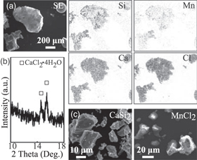
Fig. A·1. "Black and white" (a) SEM and corresponding EDS mappings of the powders annealed at 800 °C for 0 h before the washing, (b) XRD pattern of the powders obtained after evaporating the washed water, including the powders annealed at 800 °C for 0 h, (c) SEM images of the typical CaSi2 and MnCl2 original source powders.
Download figure:
Standard image High-resolution imageAppendix B
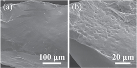
As mentioned above, although the MnSi phase was formed at the initial stage of the synthesis procedure, it was eliminated during the molten salt annealing for 10 h, leading to the formation ofF MnSi1.7 nanosheet bundles with improved structural homogeneity. The possibility of MnSi dissociation into a molten salt was examined. Commercially available crushed MnSi particles were annealed in CaCl2 molten salt at 800 °C for 10 h, and the morphological modification of the particles after annealing was observed (Fig. B·1). Furthermore, morphological evolution was observed on the surfaces of the MnSi particles. A stepped or dimpled surface was observed after annealing, indicating the possibility of the MnSi surface being etched by the molten salt or the reconstruction of the surface structure to be stabilized by low-energy surfaces. The results show that the Mn and Si atoms are more mobile in the CaCl2 molten salt environment at 800 °C.
Fig. B·1. "Black and white" SEM image of the MnSi particles (a) before and (b) after the annealing in the CaCl2 molten salts at 800 °C for 10 h.
Download figure:
Standard image High-resolution image