
Abstract
We experimentally demonstrated electrical detection of all-optical magnetization switching (AOS) induced by a single femtosecond laser pulse irradiation by measuring alternate rapid changes in anomalous Hall voltage and magneto-optic image pulse by pulse in a Hall-cross shape ferrimagnetic GdFeCo alloy thin film. We also demonstrated that the amplitude of the change in anomalous Hall voltage depended on the position of the AOS-created magnetic domain on the Hall cross. Furthermore, the AOS-created magnetic domains were stable against subsequent current applications in the Hall cross circuit, whereas reversed magnetic domains were not created when the laser pulse was irradiated with a high current. We found that the cooperative effect among magnetism, light, and electric current was assumed to have effects on the absence of the AOS. Combining the AOS phenomenon and electrical measurement/control techniques can realize ultrafast, deterministic, and distinguishable applications.
Export citation and abstract BibTeX RIS
1. Introduction
All-optical magnetization switching (AOS) with a femtosecond laser pulse has been actively studied for its ability to control magnetization at high-speed without the application of an external magnetic field. 1) Magnetization reversal induced by AOS, which occurs within a few ps, 2) is much faster than magnetization reversal with magnetization precession motion induced by an external magnetic field or spin-transfer torque.
AOS phenomenon has been observed in rare earth-transition metal (RE-TM) ferrimagnetic thin films, 1–16) and 3d transition-metal ferromagnetic thin films. 13–22) Although the femtosecond pulse laser induces a sub-ps magnetization reversal, the mechanism, including the ultrafast demagnetization and magnetic domain nucleation processes, are assumed to differ between these two material systems. Nonequilibrium thermal processes between sublattice spins play an important role in RE-TM ferrimagnetic thin films. In RE-TM ferrimagnetic thin film, such as GdFeCo, different spin dynamics between FeCo (3d) and Gd (4f) spin sublattices, which occur on a much longer timescale than the characteristic time of the exchange interaction and are followed by reproducing of antiferromagnetic exchange coupling, leads to deterministic reversal of the magnetization after the irradiation of a single femtosecond laser pulse. 2) However, in 3d transition-metal ferromagnetic thin films, the AOS is understood as stochastic nucleation of reversed domains due to the reduction of the coercivity field by laser pulse irradiation like heat-assisted magnetic recording and its following helicity-dependent domain wall motion. At least two or more laser pulse irradiations are needed to reverse the magnetization uniformly for the AOS excitation in 3d transition-metal ferromagnetic thin films. 16–18,22) Therefore, the light energy per magnetization reversal due to the AOS phenomenon is lower in RE-TM ferrimagnetic thin films than in 3d transition-metal ferromagnetic thin films. Alternatively, AOS can be induced more efficiently in RE-TM ferrimagnetic thin films. By combining the AOS phenomenon with spintronics technologies, applications with both ultrahigh-speed operation and low energy consumption can be realized. Considering these applications where magnetic recording/processing is performed in the whole memory component using AOS, while it is possible to simultaneously record/process information in multiple memory elements with a single ultrashort laser pulse, it is important to consider how to renew and maintain the magnetization state of each memory element individually. To realize these goals, electrical detection and external control methods for AOS excitation in RE-TM ferrimagnetic thin films must be established.
Since the discovery of the AOS phenomena, the main methods for evaluating AOS have been magneto-optical (MO) imaging of the size and two-dimensional shape of the magnetization reversal region. However, several studies in which the AOS phenomena are measured electrically using the anomalous Hall effect (AHE) and magnetoresistance have recently been reported. 7,8,16,18,20,21) On the other hand, most reports on the modulation of AOS in RE-TM ferrimagnetic thin films have focused on changes induced by the control of fixed parameters such as the polarization 1,3–6,12,16)/intensity 1,6,9,11,12) of the laser pulse, the sample structure, 3,4,6,11,12) and the film thickness. 6,9,12) While the mechanism of the AOS phenomenon is being studied, active control of the AOS excitation has not been investigated.
In this study, we experimentally demonstrated the electrical detection of AOS phenomena. AOS phenomenon was used to induce magnetization reversal with a single laser pulse irradiation in GdFeCo alloy ferrimagnetic thin films, and the change of Hall voltage due to the creation of the reversed domain was measured by the AHE. We also investigated the relationship between the irradiation position and anomalous Hall voltage from the viewpoint of output voltage control. In addition, to achieve external control of the AOS phenomena, we investigated the excitation of AOS phenomena with or without DC electric current flowing.
2. Experimental methods
We prepared a SiN(10 nm)/Gd23Fe67.4Co9.6(20 nm)/SiN(100 nm) thin film on a Si substrate at room temperature using magnetron sputtering. Upper SiN(10 nm) was used to prevent the oxidation of GdFeCo and to adjust the optical conditions [Fig. 1(a)]. Lower SiN(100 nm) is also used as a buffer layer of GdFeCo and electrically insulated from the substrate. The thin film was fabricated into a Hall-cross shape 50 μm wide and 800 μm long using electron beam lithography [Fig. 1(b)]. Figure 1(c) shows the result of the external perpendicular magnetic field dependence of normalized Hall voltage. Here, the external magnetic field was applied to the whole of the Hall-cross sample. The sample film in this study had clear perpendicular magnetic anisotropy with saturation magnetization of 115.5 emu cm−3, indicating that the FeCo (Gd) sublattice magnetization was parallel (antiparallel) to the net magnetization.
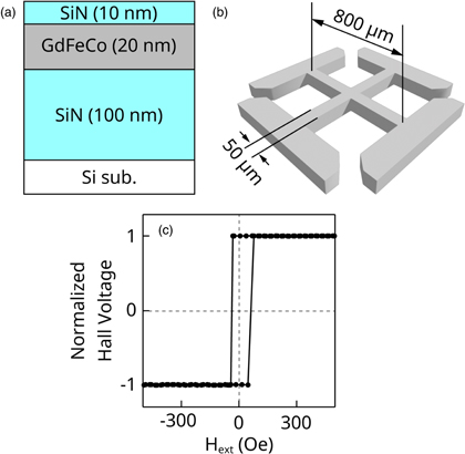
Fig. 1. (Color online) Schematic image of (a) sample structure and (b) microfabricated Hall-cross sample. (c) External perpendicular magnetic field dependence of the normalized Hall voltage.
Download figure:
Standard image High-resolution imageFigure 2(a) shows the schematic picture of the optical and electrical measurement system. A Ti:Sapphire laser system was used to emit linear-polarized laser pulses for optical excitation. The central wavelength was 800 nm and the pulse width was 35 fs. The pulse train was chopped into a single pulse with a repetition rate of 0.25 Hz using an electronic shutter. A convex lens was used to focus laser pulses on the Hall-cross sample. The Gaussian light intensity distribution was designed to have a full width at a half maximum value of approximately 30 μm on the sample surface [Fig. 2(c)]. Magneto-optical Kerr images of the sample were observed using a light-emitting diode with a wavelength of 400 nm and a charge coupled device (CCD) camera. The femtosecond pulse laser and observation light overlapped at the sample surface [Fig. 2(b)]. The polarizer and analyzer were set so that the magnetization parallel to the +z (−z) direction should be observed as light (dark) gray in MO images. The Hall-cross sample was also connected to the current source and voltmeter. A DC electric current was applied along the x direction, and the voltage induced by the AHE was measured along the y direction. Except for the initialization of the magnetization direction, no external magnetic field was applied during the experiments.
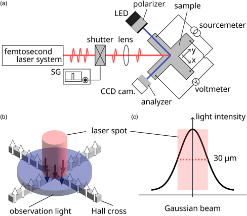
Fig. 2. (Color online) (a) Schematic picture of optical circuit and electrical measurement system. (b) The femtosecond pulse laser (small red circle) and observation light (large blue circle) overlapped at the center of the Hall cross. White (black) arrows correspond to the direction of the magnetization. (c) The converging optics were designed so that the Gaussian light intensity distribution was approximately 30 μm of full width at half maximum on the sample surface.
Download figure:
Standard image High-resolution image3. Results and discussion
3.1. Electrical detection of AOS
Figure 3(a) shows the time variation of the anomalous Hall voltage,  Before laser irradiation (
 ), the sample was magnetized to the +z direction and the anomalous Hall voltage indicated
  At
At 
 rapidly changed when the first single laser pulse was irradiated at the center of the Hall cross. Simultaneously, the contrast of the MO image at the center of the Hall cross changed from light gray to dark gray [Figs. 3(b) and 3(c)]. After that, the
  and MO images remained while the laser pulses were not irradiated. When the second single laser pulse was irradiated at
  s,
s,  changed steeply again, and an MO image similar to the initial state was simultaneously observed. After that, similar changes in the
  and MO images were repeatedly observed with each single laser pulse irradiation. These results show that the direction of FeCo magnetization at the center of the Hall cross reversed from +z (−z) to −z (+z) directions, and therefore, the
  and MO images changed after AOS was excited by the irradiation of a single femtosecond laser pulse. Let
  (
( ) the voltage after an even (odd) number of irradiations, and those two voltages were clearly distinguished even after several irradiations.
  after the second irradiation was smaller than
  because the irradiation position fluctuated [Fig. 3(a)]. It is considered that a slight misalignment between the former laser pulse and the latter one occurred due to the fluctuation of the irradiation position. Then, the inverse magnetic domains remained even after the latter pulse irradiation and
  changed due to the inverse Hall voltage from those inverse magnetic domains.
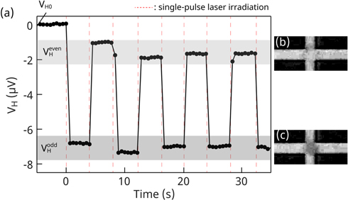
Fig. 3. (Color online) (a) Time variation of the anomalous Hall voltage. (b), (c) MO images around the center of the Hall cross captured after even-numbered and odd-numbered laser pulse irradiation. Light-gray (dark-gray) in contrast means FeCo-sublattice magnetization aligns parallel to +z (−z) direction.
Download figure:
Standard image High-resolution image3.2. Irradiation position dependence of the anomalous Hall voltage
To better understand the relationship between the steep change in  and the magnetization reversal excited around the center of the Hall cross, we measured
  by changing the irradiation position at the following points 50 μm (P), 200 μm (Q), and 450 μm (R) away from the Hall-cross center (O) in the +x direction [Fig. 4(a)]. The time variation of
  and MO images were also measured. According to the MO images obtained after the first irradiation, magnetization reversal was caused by single laser pulse irradiation at any of P, Q, and R [Fig. 4(b)]. However, the change in
 was estimated 0.46 μV at P and less than 0.03 μV at Q and R from the results of the time variation of the anomalous Hall voltage [Fig. 4(c)], which were more than ten times smaller than 4.6 μV at O [Fig. 4(d)]. Almost similar results were obtained in the −x, +y, and −y directions. These results show that magnetization reversal due to the irradiation of a single pulse around the Hall-cross center efficiently contributed to the sharp change of the
  Therefore, with precise control of the laser irradiation position, the output Hall voltage can be controlled analogously with a dynamic range of at least ten times.

Fig. 4. (Color online) (a) Schematic illustration of laser irradiated positions. (b) MO images obtained after first laser pulse irradiation at P, Q, and R. (c) Time variation of the anomalous Hall voltage obtained at P, Q, and R. (d) ∣ΔVH∣ (= ) variation with irradiation position.
Download figure:
Standard image High-resolution image3.3. Magneto-optical imaging of AOS under DC electric current
To investigate the effect of DC electric current on the AOS phenomenon, we observed AOS by changing the laser pulse irradiation timing and applying current intensity. We performed two types of experiments; (A) a single laser pulse was irradiated at  followed by DC electric current application at
  and (B) a single laser pulse was irradiated at 150 s after (
 ) the start of the current application (
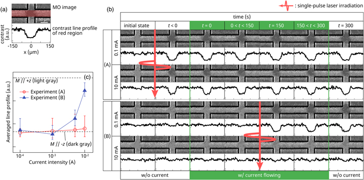
 ). In experiment (A), DC electric current was applied after the magnetization reversal caused by a single laser pulse irradiation. In experiment (B), a single laser pulse was irradiated while the current was flowing. In both experiments, the Hall-cross sample was initially magnetized in the +z direction. For these experiments, the applied current intensity varied as 0.1, 1, 5 and 10 mA. For the quantitative understanding of the MO image, we obtain the contrast line profiles along the x-axis on the Hall cross [red area in Fig. 5(a)]. Figure 5(b) shows the time variation of the MO images and the line profiles for experiments (A) and (B) with a DC of 0.1 and 10 mA. In experiment (A), the magnetization was initially saturated to +z direction and the MO contrast was light gray. The magnetization at the center of the Hall cross reversed and the MO contrast turned to dark gray when a single laser pulse was irradiated at
  . The reversed magnetic domain remained in almost the same state when a DC of 0.1 mA was flowing (
 ) and when the current flowing was stopped (
 ). Similar results were obtained when the applied current intensity increased from 0.1 to 10 mA. In experiment (B), a DC of 0.1 mA was applied at
  , and 150 s later, the magnetization reversed because of the irradiation of a single laser pulse (
 ) while the current was flowing. After that, no change in the reversed magnetic domain was observed during or after the stop of the current application (
 and
and  ). However, when the same experiment was performed with a current intensity of 10 mA, the magnetization reversal was not clearly observed by the laser pulse irradiation. To determine how the appearance of the MO contrast due to the magnetic reversal domain created under applying DC electric current changes with the variation of applied current intensity, the current intensity dependence of averaged contrast line profile between
  μm was estimated for experiments (A) and (B) [Fig. 5(c)]. In experiment (A), the variation of the current intensity has little effect on MO contrasts. However, in experiment (B), as increasing the current intensity, MO contrasts were reduced nonlinearly.
Fig. 5. (Color online) (a) MO image and contrast line profile about the red-colored area. (b) Summary of the time variation of MO images and their line profiles obtained in experiments (A) and (B) with a current of 0.1/10 mA. The red arrows mean the timing of the single laser pulse irradiation and the green box indicates the current application. (c) The current intensity variation of averaged contrast line profile between  μm. Error bars mean the dispersion in the contrast at the region of interest. The top (bottom) dashed lines represent the contrast level of the +z (−z) directional magnetized whole sample.
Download figure:
Standard image High-resolution image
3.4. Discussion
We discuss the reason why the magnetization reversal region was not created by laser pulse irradiation at a current of 10 mA from the following three aspects:
(1) Domain wall displacement due to spin transfer torque (STT).
In this study, the current density is calculated as  A m−
2 when a current of 10 mA is applied. Because the current density is approximately 10–50% that of previous studies,
23–27) the domain wall could be displaced due to STT. However, the results in experiment (A) show that the magnetic reversal domain induced by the AOS phenomenon with no electric current did not move or change its shape against a 10mA current application. Therefore, the magnetic domains induced by a single laser pulse irradiation with the current flowing is considered not to move due to STT.
A m−
2 when a current of 10 mA is applied. Because the current density is approximately 10–50% that of previous studies,
23–27) the domain wall could be displaced due to STT. However, the results in experiment (A) show that the magnetic reversal domain induced by the AOS phenomenon with no electric current did not move or change its shape against a 10mA current application. Therefore, the magnetic domains induced by a single laser pulse irradiation with the current flowing is considered not to move due to STT.
(2) Annihilation of the magnetic domain due to thermal demagnetization.
Here, we consider thermal demagnetization due to Joule heating induced by the current application. The magnetic domain induced by AOS did not disappear even after a 10 mA current was applied for 300 s, as shown using the MO image at  in Fig. 5(b). Even though the sample temperature increased during a 10mA current application, the sample temperature did not reach Curie temperature, which was expected to be between 400 and 500 K.
28–30) Therefore, the absence of the magnetization reversal region is considered not to be annihilation due to the thermal demagnetization.
in Fig. 5(b). Even though the sample temperature increased during a 10mA current application, the sample temperature did not reach Curie temperature, which was expected to be between 400 and 500 K.
28–30) Therefore, the absence of the magnetization reversal region is considered not to be annihilation due to the thermal demagnetization.
(3) Temperature dependence of AOS phenomenon.
According to Yoshikawa's study, 31) magnetization reversal induced by the AOS phenomenon was observed at 350 K in GdFeCo thin films with various composition ratios. Similar temperature dependence of AOS excitation could be observed in our study. However, the results in which the magnetic domain was not created by AOS at a temperature between room and Curie temperature are inconsistent with the previous study. Therefore, we cannot explain the origin of our results with the temperature dependence of AOS.
According to the discussions, the reason why the AOS-induced magnetization reversal domain was not created with the application of 10 mA DC current cannot be explained by only one of the above effects. The combination of STT (or electric current) and sample temperature may contribute to the magnetic domain creation process following the AOS phenomenon. On the other hand, ultrafast demagnetization or magnetization nucleation during the AOS phenomenon is assumed to be suppressed by the electric current application. Moreover, noncreation of the magnetization reversal domain against a laser pulse irradiation with an electric current application, which cannot be explained by the interaction between magnetization and light nor between magnetization and electric current, could occur only due to the cooperative effect among magnetism, light, and electric current.
4. Conclusions
We used the AHE and the MO imaging technique to detect electrically and optically the AOS phenomena induced by a single femtosecond laser pulse in a ferrimagnetic GdFeCo alloy thin film. As a result, a sharp change in the anomalous Hall voltage and MO contrast were repeatedly detected for each single femtosecond laser pulse irradiation to the center of the ferrimagnetic Hall cross circuit. The results of the laser pulse irradiation position dependence of the anomalous Hall voltage also showed that the magnetization reversal induced around the center of the Hall cross efficiently contributed to the anomalous Hall voltage, and its amplitude decreased as the irradiation position moved from the center. Furthermore, AOS excitation experiments were performed with a DC electric current application and varying the laser pulse irradiation timing, as well as current intensity. Unlike the magnetic reversal domains created by the AOS before the current application, which remained stable in position and shape during the experiment, a laser pulse irradiation with an electric current either excited or did not excite the AOS phenomena depending on current intensity. Electric current applied to the ferrimagnetic Hall-cross circuit is assumed to suppress the ultrafast demagnetization or magnetization nucleation in the AOS phenomenon. These results are assumed to show that there is a new behavior of AOS phenomenon, which occurs only when the ultrafast laser pulse is irradiated on the magnetization of RE-TM ferrimagnet with an electric current application.
To conclude, the presenting results on the ultrafast deterministic AOS provide a technologically important way to the integrated magnetic-optical-spintronic application and a new insight into the ultrafast magnetization dynamics. A combination of the precise control of AOS excitation position and the electrical detection of AHE in the ferrimagnetic Hall-cross circuit can lead to a distinguishable analog voltage output. In addition, the newly found cooperative effect among magnetism, light, and electric current on the AOS phenomenon provides new active control methods for next-generation applications such as ultrahigh-speed magnetic recording/processing devices.
Acknowledgments
This work was supported by JSPS KAKENHI Grant Numbers JP18J00338, JP19K15437, JP26103004, JP21K04184.