
Abstract
This study reports an efficient method of forming centimeter-long carbon nanotube (CNT) filaments using gas discharge breakdown. This method uses a multielectrode configuration comprising a cathode, an anode, a collection and auxiliary electrodes. The gas discharge breakdown generated between the anode and cathode coated with CNTs create a large amount of CNT dust. The auxiliary electrode controls the flow of the CNT dust formed by the gas discharge breakdown. The CNT dust finally reaches the collection electrode, and many CNT filaments longer than 20 mm are formed. By rotating the collection electrode and twisting the plural CNT filaments, the formation of CNT yarn is possible. This method is based on a novel self-assembly CNT filament formation phenomenon and enables a simple and more efficient CNT spinning than the conventional methods. Additionally, this method may enable the spinning of CNTs that are difficult to spin by the conventional methods.
Export citation and abstract BibTeX RIS
1. Introduction
Carbon nanotubes (CNTs) 1) possess many unique characteristics, such as excellent mechanical strength, remarkable flexibility, and high electrical and thermal conductivities, 2–4) which originate from the one-dimensional structure with a remarkably small diameter, comprising sp2-hybridized carbon atoms. These characteristics have attracted much interest from many researchers, motivating research activities regarding various applications of CNTs. 5–18) CNT yarn is one of the most promising CNT applications. CNT yarns are long assemblies of CNTs in which CNTs or CNT bundles are interlocked continuously. 19–32) CNT yarns enable the fabrication of lightweight and high tensile strength cables and textiles with high electrical and thermal conductivities. They can be used for various applications, such as lightweight and high tensile electrical wires and cables.
Conventional formation of CNT yarns is performed by solution-based spinning, 19,20,24) direct spinning from a chemical vapor deposition (CVD) reactor, 21,23,25,29) and spinning from vertically aligned CNTs grown on planar substrates (CNT forest spinning). 26–28,32) The formation of CNT yarns by these methods has been reported by many researchers until now. However, the abovementioned methods have some drawbacks. The solution-based spinning requires short-length CNTs (typically several microns) because the dispersion of CNTs into solvents is easier for shorter CNTs. This method also requires a complicated spinning process. In the direct spinning from a CVD reactor, the CNTs used for spinning are limited to those that the CVD reactor can synthesize. Therefore, the equipment for this method becomes large and complicated. The CNT forest spinning can only be performed using several hundred micrometers of long and vertically aligned CNTs with morphologies favorable for spinning, which is generally difficult to control. Additionally, this method requires substrates, such as silicon wafers, for the CNT growth. As mentioned above, these methods are limited in the kind of CNTs that can be used to form CNT yarns.
We have reported a CNT filament formation phenomenon induced by gas discharge breakdown between a pair of electrodes (an anode and a cathode) coated with CNT film. 33–35) Many filament-like CNT bundles are formed between the anode and cathode by the gas discharge breakdown effect between them. The CNT film exposed to the gas discharge breakdown creates many CNTs detached from the CNT mat. These CNTs are connected to each other and reconstituted into long filaments.
We also found that using a wire-shaped anode and a plate-shaped cathode on which the CNT mat was attached created a large amount of dust-like CNTs from the CNT mat. 36) The dust-like CNTs were collected and formed tree-like CNT filaments densely around the wire-shaped anode. Furthermore, we found that adding a third electrode, which served as a collection electrode of CNT filaments, to the wire-shaped anode and the plate-shaped cathode drastically enhanced the formation of the CNT filaments on the collection electrode. The length of the CNT filament reached ∼10 mm. We considered this phenomenon promising for a versatile dry spinning method for various kinds of CNTs that cannot be spinned by conventional methods. However, the CNT filament formation efficiency should be further enhanced to use this phenomenon for CNT spinning. Additionally, a proper handling method of the CNT filaments is required for the CNT spinning.
Here, we attempted to enhance the CNT filament formation efficiency by using a multielectrode configuration comprising an anode, a cathode, an auxiliary electrode, and a CNT collection electrode. In this structure, the anode and the cathode generate the gas discharge breakdown required to create the dust-like CNT bundles from the CNT mat attached to the cathode. The auxiliary electrode extracts the charged CNT dust from the region between the anode and the cathode. Finally, the collection electrode collects the CNT dust on the electrode surface and promotes the formation of the CNT filaments. We investigated the formation behavior of CNT filaments under various bias voltages applied to the auxiliary and collection electrodes. Also, we attempted to form a CNT yarn by spinning the long CNT filaments formed around the collection electrode.
2. Experimental methods
The multielectrode setup used herein is shown in Fig. 1. This setup comprises four electrodes: a cathode, an anode, an auxiliary electrode, and a CNT collection electrode. The cathode is a stainless-steel plate (grade 304) with a size of ∼10 mm × 10 mm × 0.5 mm). The cathode plate was attached to a glass plate with an adhesive bond (Araldite, Huntsman Corp.). The anode, auxiliary electrode, and CNT collection electrode are wire-shaped electrodes. A tungsten wire (Nilaco corp., purity 99.95%, 0.15 mm diameter) was used for the wire electrodes. Burrs on the tip of the anode wire were removed by electropolishing in a 5 mol l−1 NaOH aqueous solution. The wire anode was placed between the plate cathode and the auxiliary electrode, parallel to the edge of the cathode plate, where a CNT mat was attached. The wire anode was fixed on the stainless-steel plate (different from the cathode plate) with a screw. The distance between the anode and cathode was 1.0 mm. The auxiliary electrode was attached to linear motion feedthrough and was placed vertically to the edge of the cathode plate and anode wire. The distance between the anode and the apex of the auxiliary electrode was adjusted to 1.0 mm. The CNT collection electrode was placed vertically to the other side of the edge of the cathode plate; parallel to the anode and vertically to the auxiliary electrode. The collection electrode was attached to a linear motion-rotation feedthrough, thereby enabling the change in distance between the collection electrode and the cathode. Furthermore, this enables the rotation of the collection electrode. The initial distance between the cathode and the collection electrode was ∼10 mm.
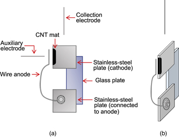
Fig. 1. (Color online) Schematic illustrations of discharge electrodes: (a) front and (b) bird's-eye views.
Download figure:
Standard image High-resolution imageThe CNT mat used herein comprises multiwall CNTs synthesized by a thermal CVD. Detailed conditions of the CNT synthesis and procedure for the CNT mat production have been described elsewhere. 36) Vertically aligned multiwalled CNTs (MWCNTs) with an average diameter of 10 nm were grown on silicon substrates by thermal CVD using acetylene as a carbon source gas. 37) The length of CNTs used herein was 147 ± 10 μm. The CNTs grown on silicon substrates were put in a vial with ethanol, and the CNTs were dispersed in ethanol by ultrasonication to prepare a CNT-dispersed ethanol solvent. Then, the solvent was heated to evaporate the ethanol. Mat-like CNT aggregates were formed at the bottom of the vial after completely removing the ethanol. The CNT mats obtained by this procedure were attached to the edge of the cathode plate.
Afterwards, the multielectrode was placed in a discharge chamber (Fig. 2). The cathode, the auxiliary electrode, and the CNT collection electrodes were connected to the DC power supplies. These voltages could be biased independently to arbitrary voltages, and the anode was grounded. The chamber was evacuated to <3 Pa by a mechanical rotary pump. Next, Ar was introduced to a predetermined pressure. Herein, 6.2 kPa of Ar pressure was used based on the result of the preceding study. 36) Gas discharge breakdown was then generated between the wire anode and the edge of the cathode plate by applying a DC voltage of −800 V to the cathode. A digital camera observed and recorded the filament formation behavior during the gas discharge breakdown (Nikon D-7500). The frame rate used for image capture was 60 frames per second.
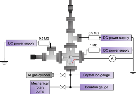
Fig. 2. (Color online) Schematic image of an experimental setup for carbon nanotube (CNT) filament formation by gas discharge breakdown.
Download figure:
Standard image High-resolution image3. Results and discussion
Figure 3 shows video snapshots revealing the temporal change of CNT dust formation and subsequent CNT filament formation around a CNT collection electrode induced via gas discharge breakdown. The original video can be found in supplementary information (Video 1 available online at stacks.iop.org/JJAP/62/SA1010/mmedia). The applied voltages to the auxiliary and CNT collection electrodes were 0 and +50 V, respectively. Figure 3(a) is a photograph of the electrodes just before the discharge breakdown ignition. The application of −800 V to the cathode generated the gas discharge breakdown between the anode and cathode. Figure 3(b) shows the situation 5 s after the discharge ignition. It can be confirmed that CNT dust, which appears as smoke rising from the discharge breakdown, is created between the anode and cathode, and flows toward the CNT collection electrode. After 15 s of ignition, short CNT filaments are formed on the collection electrode [Fig. 3(c)]. The filaments gradually elongate with time. Finally, some filaments reached the cathode [Fig. 3(d)].

Fig. 3. (Color online) Video snapshots showing the temporal change in CNT dust formation and subsequent CNT filament formation around the CNT collection electrode induced via gas discharge breakdown: (a) electrodes just before ignition of discharge breakdown. (b)–(d) Electrodes 5, 15, and 35 s after ignition of gas discharge breakdown, respectively. Applied voltages to the auxiliary and CNT collection electrode are 0 and +50 V, respectively. Scale bars are 5.0 mm.
Download figure:
Standard image High-resolution imageTo determine the voltage applied to the auxiliary electrode, we next examined the dependence of the CNT filament formation characteristics on the bias voltage applied to the auxiliary electrode. Figure 4 shows video snapshots revealing the dependence of the CNT filament formation behavior during gas discharge breakdown on the bias voltage applied to the auxiliary electrode. Herein, the voltage applied to the collection electrode was fixed at +50 V. The result without the bias voltage applied to the auxiliary electrode (i.e. the electrode was grounded) has already been shown above (Fig. 3). A similar feature was also seen in the gas discharge breakdown with +50 V of the bias voltage applied to the auxiliary electrode (not shown here). The CNT filament formation with +100 V of the bias voltage gave a quite different feature of the CNT filament formation [Figs. 4(a) and 4(b)]. Long CNT filaments floating around the electrodes are seen in Fig. 4(a). These floating CNTs are then captured on the cathode (outside the discharge area) or the CNT collection electrode. Finally, long CNT filaments connecting the cathode and the collection electrode are formed [Fig. 4(b)]. At this time, a clear flow of CNT dust seen in Fig. 3 was not observed. The original video of Figs. 4(a) and 4(b) can be found in supplementary information (Video 2 available online at stacks.iop.org/JJAP/62/SA1010/mmedia). Similar behavior of the CNT filament formation was observed in the gas discharge breakdown with +150 and +200 V of the bias voltage applied to the auxiliary electrode [Figs. 4(c) and 4(d)]. These results show that the bias voltage of +100 V or higher applied to the auxiliary electrode gives longer CNT filament formation.

Fig. 4. (Color online) Video snapshots showing the dependence of CNT filament formation behavior during gas discharge breakdown with a different bias voltage to the auxiliary electrode. (a) and (b) Photographs showing CNT filament formation behavior with +100 V of the bias voltage after 51 and 88 s from the start of gas discharge breakdown, respectively. (c) and (d) CNT filaments formed with +150 and +200 V of bias voltages. Scale bars are of 4.0 mm. Voltage applied to the collection electrode is +50 V.
Download figure:
Standard image High-resolution imageNext, we examined the dependence of the bias voltage on the CNT collection electrode of the CNT filament formation. Here, the bias voltage to the auxiliary electrode was fixed at +100 V. The collection electrode was moved upward and downward after the gas discharge breakdown ignition to capture the CNT filaments efficiently on the collection electrode. The video snapshots of the CNT filament formation recorded for different bias voltages are shown in Fig. 5. Here the images of the CNT filaments after the stopping the discharge breakdown are shown. Figure 5(a) shows the CNT filaments formed on the CNT collection electrode with a bias voltage of 0 V. Some CNT filaments are formed between the apex of the collection electrode and the cathode. The amount of the CNT filaments drastically increased by applying the bias voltage. Figure 5(b) shows the CNT filaments formed with a bias voltage of +50 V applied to the collection electrode. The formation of more CNT filaments than that of the bias voltage of 0 V was observed during the gas discharge breakdown. These CNT filaments finally formed a bundle. A bias voltage of +100 V also formed several CNT filaments [Fig. 5(c)]. A much higher bias voltage (+150 V) also gave the CNT filament formation [Fig. 5(d)]. However, the number of CNT filaments decreased compared with that of +100 V.

Fig. 5. (Color online) Video snapshots showing the dependence of CNT filament formation behavior induced by gas discharge breakdown on bias voltage to the CNT collection electrode. Voltages applied to the collection electrode are (a) 0, (b) +50, (c) +100, and (d) +150. Scale bars are of 4.0 mm. Voltage applied to the auxiliary electrode is +100 V.
Download figure:
Standard image High-resolution imageFrom the results shown above, we determined that the conditions suitable for the formation of CNT filaments are +100 and + 50 V applied to the auxiliary and CNT collection electrodes, respectively. At this condition, we attempted to form a CNT yarn. The CNT filaments were first formed by the abovementioned conditions to achieve this step. Then, the discharge breakdown was stopped, and the collection electrode was rotated to twist the CNT filaments to form CNT yarn. At this time, the application of the bias voltage to the collection electrode (+50 V) was continued. Figure 6 shows the CNT filaments on the collection electrode that gradually changes into yarn as the collection electrode rotates. Figure 6(a) shows the CNT filaments formed by the above condition. The upper and lower parts of the filaments are attached to the apex of the collection electrode and the cathode surface, respectively. From this state, the collection electrode is rotated. The CNT filaments are then twisted and gradually changed into bundles as the collection electrode is rotated [Fig. 6(b)]. The bundled part elongates as the number of rotations increases [Fig. 6(c)]. Finally, the CNT filaments are completely changed into the yarn [Fig. 6(d)]. In this process, the collection electrode was rotated 40 times. The CNT yarn formed by this process was taken out from the discharge chamber and observed (Fig. 7). The CNT yarn with ∼30 mm length was confirmed. The CNT yarn is strong enough to be pinched and handled by tweezers (Fig. 7). Observations of the yarn by scanning electron microscope were also conducted and shown in supplementary information (Fig. A·1 available online at stacks.iop.org/JJAP/62/SA1010/mmedia). Evidently, the morphology is not well-ordered, and the high magnification image shows that the CNTs in the yarn are randomly oriented and sparse because the twist of CNT yarn is not sufficient at the moment.
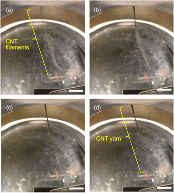
Fig. 6. (Color online) Video snapshots showing CNT yarn formation by twisting CNT filaments formed on the CNT collection electrode. (a) CNT filaments before twisting. (b)–(d) CNT filaments gradually change to CNT yarn by rotating the collection electrode. Numbers of rotations are of (b) 10, (c) 20, and (d) 40 turns, respectively. Scale bars are 5.0 mm.
Download figure:
Standard image High-resolution image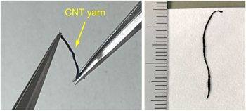
Fig. 7. (Color online) Photograph of CNT yarn formed herein.
Download figure:
Standard image High-resolution imageThe above results indicate that efficient CNT filament formation is possible using the multielectrode configuration shown in Fig. 1. Thus, the bias voltages applied to the auxiliary and collection electrode are critically important. Next, we discuss the role of the bias voltages applied to the electrodes on the CNT filament formation.
The formation mechanism of the CNT filaments by the gas discharge breakdown has been discussed elsewhere in detail. 33,36) Briefly, the CNT dust was created by irradiating the gas discharge breakdown to the CNT mat attached to the cathode. The CNT mat is a pure CNT aggregate in which the CNTs are entangled and connected by van der Waals interaction. The irradiation of ions on the mat causes the ion bombardment of the CNTs on the mat. This bombardment causes a destructive morphological change in the mat surface, which creates many liberated CNT bundles from the CNT mat. These liberated CNT bundles are extracted from the CNT mat by the electric field effect on the cathode. The CNTs and CNT bundles liberated from the mat are negatively charged. Afterward, the liberated CNT bundles depart the cathode. These liberated CNT bundles form the CNT dust around the electrodes. The CNT dust is attracted to electrodes other than the cathode, and the CNT bundles in the dust are captured on it. The captured CNT bundles attract other CNT bundles and connect. Repetition of this process creates longer CNT filaments. This discussion is based on the CNT filament formation using the triode configuration comprising the anode, cathode, and collection electrode. 36) However, it is considered that the exact mechanism of the CNT filament formation can be applied here.
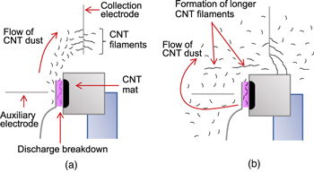
Based on the CNT filament formation mechanism mentioned above, the role of the auxiliary electrode in the CNT filament formation is first considered. The results shown in Figs. 3 and 4 indicate that applying the bias voltage to the auxiliary electrode gives longer CNT filaments. The formation processes of the CNT filaments differed between the process with the application of lower (0 and +50 V) and higher (+100 and +150 V) bias voltages to the auxiliary electrode. The CNT filament formation with a lower bias voltage showed smoke-like CNT dust rising upward and flowing directly to the collection electrode (Fig. 3). The CNT filaments were formed on the collection electrode surrounded by the CNT dust. In contrast, a higher bias voltage formed long CNT filaments floating around the electrodes (Fig. 4). These filaments were finally captured on the collection electrode or the cathode and connected. This difference can be explained as follows: the CNT bundles liberated from the CNT mat on the cathode by the irradiation of gas discharge breakdown are first accelerated to the anode because these are negatively charged. Due to its thin wire shape, the more significant part of the CNT bundles is not captured on the anode and passes through it. When the voltage applied to the auxiliary electrode is not high (<+100 V), the CNT bundles are attracted to the positively biased CNT collection electrode. These CNT bundles form the CNT dust that flows directly toward the collection electrode [Fig. 8(a)]. The CNT bundles in the dust become a constituent of the CNT filaments formed on the collection electrode. When the voltage applied to the auxiliary electrode is high (≥+100 V), the CNT bundles are not attracted to the CNT collection electrode, but the auxiliary electrode [Fig. 8(b)]. At this time, the CNT bundles are further accelerated toward the electrode. The auxiliary electrode also has a thin wire shape. Thus, the large part of the CNT bundles attracted to the auxiliary electrode is also not captured on the auxiliary electrode. Consequently, the CNT bundles move toward a direction different from the direction of the collection electrode and spread around the electrode. Several CNT bundles drifting around the electrode are connected by electrostatic force and form longer CNT filaments [Fig. 8(a)]. These long CNT filaments floating around the electrodes are finally captured on the CNT collection electrode and form many CNT filaments. These filaments connect between the collection electrode and the cathode [Figs. 4(b)–4(d)]. In short, the auxiliary electrode serves as a deflector that increases the drifting distance of the CNT bundles from the CNT mat to the collection electrode. This increase in the drifting distance promotes the formation of CNT filaments.
The bias voltage dependence on the CNT collection electrode (Fig. 5) also clearly shows that applying the voltage to the electrode is important for the CNT collection efficiency. The result in Fig. 5 indicates that +50 to +100 V of the bias voltage is sufficient for collecting CNT filaments, and an excessive voltage (+150 V) decreases the number of filaments. This trend indicates that excessive acceleration of the CNT filaments by a higher electric field decreases the efficiency of capturing CNT filaments on the collection electrode. Additionally, applying a higher voltage (+100 and +150 V) often causes burning out of the CNT filament formed between the collection electrode and the cathode due to excessive current flow. From these results, +50 V of the bias voltage was the optimum condition noted here.
Also, the transmission electron microscopy and Raman analysis of the CNTs comprising the filaments formed by the gas discharge breakdown showed that the CNTs in the filaments maintained their original tubular and graphitic structures. 36) Thus, it is possible to form the CNT filaments that have the same quality as the as-prepared CNTs by the gas discharge breakdown method.
Once the CNT filaments are formed between the collection electrode and the cathode, it is possible to form the CNT yarn by simply rotating the collection electrode (Fig. 6). The CNT yarn is strong enough to be pinched and handled by tweezers (Fig. 7), but can be easily broken by pulling it with the tweezers. As mentioned above, the CNTs in the yarn were randomly oriented and had sparse morphology (Fig. A·1) because of the insufficient twists of the CNT yarn. To strengthen the tensile strength of the CNT yarn, adding enough twists during the spinning is needed. This approach will improve the morphology of the CNTs in the yarn and, consequently, the strength of the yarn. Adding enough twists during the spinning will be realized by modifying our equipment. Our results show that this process is promising for the simple formation method of CNT yarn using CNTs that are difficult to form, such as single wall CNTs.
Fig. 8. (Color online) Illustrations of the difference in the CNT filament formation process by the application voltage to the auxiliary electrode. (a) and (b) Behavior of CNT dust when low (0 or +50 V) and high (+100 or +150 V) voltages are applied to the auxiliary electrode, respectively.
Download figure:
Standard image High-resolution image
4. Conclusions
Here, we attempted to enhance the CNT filament formation efficiency using a multielectrode configuration comprising an anode, a cathode, an auxiliary electrode, and a CNT collection electrode. We investigated the formation behavior of CNT filaments under various bias voltages applied to the auxiliary and collection electrodes. The results showed that the applications of the voltages to the auxiliary and collection electrodes promote the formation of a longer and larger number of CNT filaments, which is sufficient to spin and form the CNT yarn on the collection electrode. We also successfully formed the CNT yarn by simply rotating the collection electrode on which CNT filaments were formed. Further improvement of the CNT yarn formation is in progress for evaluating the mechanical strength and electrical conduction properties of the CNT yarn. This process enables the formation of CNT yarn using CNTs that were difficult to form, such as single wall CNTs. The formation of CNT yarn using single wall CNTs is also in progress.
Acknowledgments
This study was supported by JSPS KAKENHI (Grant Nos. 19K05206 and 22K04872) and the Alumni Association of Faculty of Engineering, Mie University.