
Abstract
A wireless power transfer (WPT) circuit was developed for an inorganic electro-luminescent (EL) device. When transmission and receiver circuits are both in resonant mode, low operating voltage of 30 V was enough to achieve the EL luminance as high as 180 cd m−2. As for the transmission and the receiver coils, different types and shapes are studied to clarify those effects on the EL luminance and transmission efficiency. Solenoid coils generally presented higher luminance than other types. Polygonal solenoid coils resulted in even higher luminance and transmission efficiency than circular solenoids. A spiral or a spider coil, in which air core area is much smaller than the solenoid coil, was found to be less sensitive to coil displacement. The difference in EL performances with the variation of coils suggests the possibility of further improvement the WPT system.
Export citation and abstract BibTeX RIS
1. Introduction
A wireless power transfer (WPT) system is known as a technology to enable non-contact power transfer without power cables. 1,2) Demands for a wireless power charging system for today's electronics products such as electric vehicles (EV), 3) smartphones, 4,5) and home appliances 6) are high, as it facilitates contactless battery charging. A magnetic coupling method, which utilizes two magnetically coupled coils to transfer electric power, is a widely accepted technique as a WPT system. When resonant capacitors are added to the transfer and receiver coils to satisfy the resonant condition, a longer transfer distance is known to be achieved, and this configuration is called magnetic resonance coupling. 1) One of the challenges for the above-mentioned WPT systems is the decrease in transfer efficiency when misalignment occurs between the transfer and the receiver coils. Long-range transfer distance should be also achieved at the same time for more practical applications.
A simple cordless lighting system can be realized when an inorganic electroluminescent device is used in the secondary circuit of a WPT system. An inorganic electro-luminescent (EL) device utilizes electroluminescence of an inorganic phosphor layer sandwiched with two sheet-like electrodes and driven from an ac power source. A dielectric layer is usually employed in order to regulate the ac current. There are two types of inorganic EL devices: a thin film type 7) and a powder type. 8,9) In the case of the thin film type, the phosphor and the dielectric layer are deposited by a vacuum process. The phosphor or the dielectric layers of the powder type, also referred to as a dispersion type EL, on the other hand, is a mixture of phosphor or dielectric powders and binder resins, which is usually wet coated or screen printed. 10) As the curing temperature of the powder type is as low as 100 °C, plastic films are common substrate materials. Several studies have been made so far to improve the brightness and the efficiency of powder EL. 11–13) Recently, tracing papers or carbon non-fibers (CNF), 14) and textiles 15) are also proposed as the substrate material of the powder EL. As the result, powder EL enjoys many advantages such as flexibility, lightweight, and low manufacturing cost. Lower brightness and higher driving voltages (100–600 cd m−2, at 100–300 V) 9,11,14) than OLED are, however, substantially limiting the market area of powder EL. Particularly, driving voltages that normally exceed 100 V prevent the powder EL from being widely used in the electronics market.
The authors have investigated the structure of the material for the powder EL so far. 12,16–18) The possibility of wireless driving of the powder EL device as a future light source was also shown. 19) Since a long-range WPT circuit was first demonstrated with a 60 W light bulb, 2) WPT systems for lighting applications were reported using LED, 20) fluorescent lamps, 21) and OLED. 22,23) Wireless driving of the dispersion type or powder EL is beneficial, as the high voltage (>100 V) power cable is not necessary, which enhances the safety and reliability of the lighting system. The use of the powder EL in the WPT system can also realize a flexible sheet-like light source without a power connection.
In this study, magnetic resonance coupling circuits as a WPT system for a powder EL are evaluated using various types and shapes of coils. Keeping a practical lighting system in mind, a relatively large (∼A4) size powder EL device was manufactured. An AFM observation of the surface of the device helped us to ensure a stable operation free from electrical breakdowns throughout experiments. As a WPT system, the EL luminance and transfer efficiency when the coils are misaligned were investigated in detail. It was found that both the primary and the secondary circuits should be in the resonant condition in order to obtain the maximum brightness at significantly low driving voltages as low as 30 V. As for the misalignment, the displacement distance between the primary and the secondary coils more than 100 mm was achieved in the resonance condition. The present results will give insights into the WPT system with a capacitive load, on which little previous research is found in the literature.
2. Magnetic resonance coupling system
A WPT system investigated in this study is based on the magnetic coupling between two coils, which principle is utilized in other devices such as a transformer. When a time-varying magnetic flux induced by ac current flowing in the primary coil intersects with the secondary coil, there arises an electromotive force on the secondary coil according to Faraday's law. When a load is connected in parallel to the secondary coil, electric power is transferred from the primary to the secondary circuit.
Efficient power transfer is achieved when the resonance frequency of the primary and the secondary circuit is matched. 1,2) This type of WPT is called a magnetic resonance coupling circuit (Fig. 1). The magnetic resonance coupling can deliver high electric power when the resonance frequency of the primary and the secondary circuit is carefully tuned.
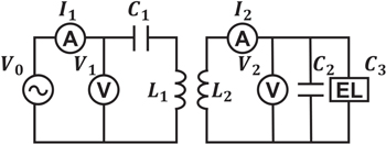
Fig. 1. Wireless power transfer (WPT) circuit for an inorganic EL device.
Download figure:
Standard image High-resolution imageWe tuned the resonance frequencies by capacitors connected in series (C1) to the primary and in parallel (C2) to the secondary coils, the inductances of which are L1 and L2. The resonance frequency f1 of the primary circuit is expressed as

and that of the secondary circuit, f2 is

where, C3 is the effective capacitance of the inorganic EL.
The advantage of employing the inorganic EL as a load is that it serves as a resonant capacitor (C3), which makes the secondary circuit quite simple. In this study, an additional film capacitor C2 was connected in parallel to the EL so that the resonance frequency settles within a desirable range to drive the EL (1–3 kHz). 24) As a result, the experimental circuit consists of minimal components as shown in Fig. 1. If an EL with the appropriate area is employed, capacitor C2 is possibly eliminated, as the capacitance of EL is proportional to its area size.
The transmission efficiency η is calculated as

where V1 and V2 are the voltage across the primary and the secondary circuits, respectively, and I1, I2, the current flowing the primary and the secondary circuits. Angles θ1 and θ2 are the phase differences between the voltages and the currents.
3. Experiment
3.1. Inorganic EL sample and AFM observation
Figure 2 shows the cross-sectional view of a powder-type inorganic EL prepared in this study. The substrate is a glass plate coated with an indium tin oxide (ITO) transparent electrode. The thickness of the glass is 1.1 mm. Commercially available EL phosphor powders (ZnS:Mn) 14,25) were dispersed in a solution of binder resin, and coated on the ITO layer. The coating method was a so-called blade or knife coating, 15,26) in which a cylindrical bar was manually moved to spread the material keeping a constant gap from the substrate surface. A dielectric layer was also coated with the same process as the phosphor layer. The dielectric material is BaTiO3 powders, the particle size of which is about 0.5 μm. The wet layers were heat-dried at 100 °C for 20 min after each coating process. The thickness of the phosphor and the dielectric layers is about 100 μm each after drying. Finally, a silver paste was knife coated on the dielectric layer as a back electrode. The active area size of the sample EL is 210 mm by 310 mm.

Fig. 2. (Color online) (a) Cross-sectional view of the experimental inorganic EL device. (b) AFM image of ITO thin film deposited on glass substrate. (c) AFM image of BiTiO3 on the phosphor layer (ZnS:Mn)/ITO thin film/glass substrate.
Download figure:
Standard image High-resolution imageAs the active area is relatively large, the thickness uniformity of each layer is essential for brightness uniformity and stable operation. While a large area uniformity is ensured by employing the knife coating process, a small-scale uniformity depends mainly on the material characteristics, which should be evaluated before the coating process. As the average particle size of the phosphor powder is around 25 μm, the surface roughness of the phosphor layer is in the same order as this particle size. 13) The dielectric layer should cover this roughness of the phosphor layer. The average particle size of the dielectric powder is 0.5 μm, and it is possible to make the surface smooth enough provided that there is no agglomeration of the powders. Sub-micrometer powders, however, are apt to agglomerate and may cause small scale non-uniformity and, in the worst case, deterioration of the withstanding voltage. Particularly, electrical breakdowns caused by low withstanding voltage can be a fatal defect for the large size device. To evaluate the smoothness of the dielectric layer, we observed its surface by AFM.
Our AFM system used in this study was based on an optical-beam-deflection scanning probe microscope system (SPI4000 SII NT, Japan), and tip height control was carried out at a scanning speed of 1 Hz. The cantilever was mechanically vibrated at a frequency f for observing topography. We used a Si-based cantilever whose spring constant and resonant frequencies were approximately 20 N m−1 and 259 kHz, respectively. The frequency f for the mechanical vibration of the cantilever was normally tuned at 500 Hz–1 kHz lower than its resonant frequency. Figures 2(b) and 2(c) show AFM images of the ITO thin film deposited onto the glass substrate, and BiTiO3 on the phosphor layer (ZnS:Mn)/ITO thin film. The AFM imaging was carried out in the tapping mode with a scanning speed of 1 Hz at room temperature. The brighter regions in the topographic images represent an elevated height.
The average roughness of the ITO thin film on the substrate is less than 20 nm in most of the area as seen in Fig. 2(b). There are bumps (bright spots) of 50 nm or so in some areas. The overall uniformity of the ITO film seems to be enough as a starting layer for a powder EL device. From the AFM image of the dielectric layer [Fig. 2(c)], the BiTiO3 powders can be seen as bright spots. The distance between these spots being several hundreds of micrometers or more, it is concluded that there is no agglomeration of the powders affecting the layer uniformity. Also, the difference between the maximum and minimum heights is less than 1 μm. This is smooth enough for the current device, which has a layer thickness of more than 100 μm.
3.2. Circular coils
Three types of air-core circular inductors (coils) were manufactured for the experimental WPT circuits. Their effects on the EL luminance and the transmission efficiency were evaluated. Coils of the same design were used both for the primary and the secondary circuit.
A spiral coil 27,28) prepared for the current study is a planar (single layer) inductor, the thickness of which is in the order of the wire diameter as shown in Fig. 3(a). The wire was wound around a thin center sheet, held between two metal blocks. There were laminate films on the inner surface of the metal blocks. After winding, the metal blocks were pressed together and heated at 100 °C, thus a film-laminated planar coil is finished.
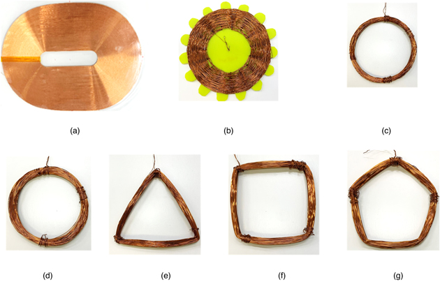
Fig. 3. (Color online) Photographs of coils prepared for the WPT experiment; (a) circular spiral coil, (b) circular spider coil, (c) and (d) circular solenoid coils, (e) triangular coil, (f) square coil, and (g) pentagonal coil. The size and electrical parameters are shown in Tables I and II.
Download figure:
Standard image High-resolution imageThe inductance measured was 14.6 mH. When looked at from the axial direction, the area of the conductor is the largest of all, and the air core size is the smallest. A spider coil, or a spider web coil 29,30) is wound around a star-shaped form that has an odd number of tubs as shown in Fig. 3(b). The thickness of the coil is at least several times thicker than the wire diameter. The area of the conductor is the second largest, and the inductance was 17.0 mH. A solenoid coil 27) shown in Fig. 3(c) is an air-core circular coil. The wire is first wound around a cylinder body. The coil is removed from the cylinder after the winding process and covered by an insulator tape. The air-core size is the largest of all, while the thickness of this coil is in the order of centimeters. The inductance was 14.5 mH. The parameters of each coil are summarized in Table I. The wire diameter of all the coils was 0.6 mm.
Table I. Three different coil types and those parameters.
| Coil type | Spiral | Spider | Solenoid |
|---|---|---|---|
| Number of turns | 250 | 200 | 250 |
| Inductance L (mH) | 14.6 | 17.0 | 14.5 |
| Resistance (DC) (Ω) | 48 | 63 | 28 |
| Size (longer side) (mm) | 286 | 160 | 140 |
| Photographs in Fig. 3 | (a) | (b) | (c) |
3.3. Procedures of experiments
At first, the electrical and optical characteristics of the sample EL were evaluated. The sample EL was directly driven by a sine wave from an ac power supply at the frequency of 2.0 Hz as shown in Fig. 4. As the EL current leads the EL voltage by 60°or more, the equivalent circuit of the EL can be expressed as the series resistor R and the capacitor C2. Here, resistor R represents the power consumption at the phosphor layer of the EL device.
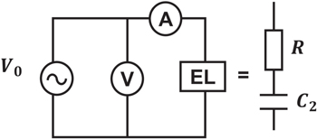
Fig. 4. Wired circuit to evaluate the EL characteristics, and the equivalent circuit of EL.
Download figure:
Standard image High-resolution imageThe applied voltage V0 (=EL voltage) was increased from 0 V to 100 V. Thus, the relation between the EL voltage and its luminance and the current was obtained. All ac voltages are shown in rms values hereafter.
Next, WPT experiments were carried out using the circuit shown in Fig. 1. Identical coils picked up from one of the three types (Table I) were employed for L1 and L2. The resonance frequency of the primary circuit f1 is adjusted to 3.0 kHz. The capacitance of the secondary circuit was tuned by an additional capacitor C2 so that it becomes the same value (f1 = f2) as that of the primary circuit.
The electrical characteristics and the luminance of EL were measured for driving frequencies of 1.0–3.5 kHz, which includes the resonance frequency. The driving voltage V0 was fixed at 30 V.
Finally, polygonal solenoid coils were prepared to evaluate the effect of the shape of the coils. At the corner of the polygonal coils, the magnetic flux may concentrate or change causing different effects on the overall WPT characteristics. 31) In addition to the circular solenoid coil, a triangular, a square, and a pentagonal solenoid coils were manufactured as shown in Figs. 3(d)–3(g). The coil parameters were summarized in Table II. These coils were used in the circuit in Fig. 1, the resonance frequency f1 (=f2) of which is also tuned to about 3 kHz. The source voltage V0 is fixed at 30 V again. The purpose of this experiment is to evaluate the effect of the coil shape on the transmission efficiency and the EL luminance when the displacement distance between the two coils is changed.
Table II. Three different coil types and those parameters.
| Coil type | Circular | Triangular | Square | Pentagonal |
|---|---|---|---|---|
| Number of turns | 100 | 100 | 100 | 100 |
| Inductance L (mH) | 2.3 | 2.6 | 2.9 | 3.0 |
| Resistance (DC) (Ω) | 5.8 | 4.9 | 5.0 | 5.1 |
| Size (longer side) (mm) | 107 | 140 | 110 | 120 |
| Photographs in Fig. 3 | (d) | (e) | (f) | (g) |
4. Results and discussions
4.1. EL characteristics
Figures 5(a) and 5(b) show the EL luminance and the EL current when the EL is driven directly by an ac power supply of f = 2.0 kHz. The supply voltage V0 was increased from 0 to 100 V at the step of 5 V. The threshold voltage is about 20 V, and both the luminance and the current increase almost linearly as the supply voltage increases. The maximum luminance of 300 cd m−2 was measured at the voltage of 100 V. Quite high luminance was obtained but the driving voltage is also high.
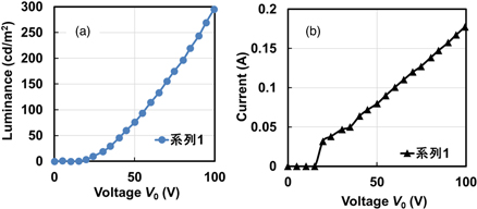
Fig. 5. (Color online) EL Luminance and current versus applied voltage in wired circuit. The EL is directly operated by an ac power source at 2.0 kHz. (a) Luminance, (b) EL current.
Download figure:
Standard image High-resolution imageThe equivalent capacitance C3 and resistance R of the EL at 70 V, 2.0 kHz is calculated to be 150 nF, and 250 Ω, respectively, from the obtained voltage and current waveforms. The reactance of the capacitor C3 being 530 Ω, the power factor (cos θ) of the EL is 0.43 and is quite capacitive as a load.
4.2. WPT experiments with different types of coils
The luminance of the wireless operated EL versus EL voltage V2 driven at 2.0 kHz is plotted in Fig. 6(a) for the circular solenoid coil shown in Table I [Fig. 3(c)]. The coils with the same design were used for the primary and the secondary circuit. The vertical distance (gap L) and the displacement of the coils D [Fig. 6(b)] is kept zero, that is, the two coils are closely attached to each other during the measurements. The luminance of the wired EL is also plotted in Fig. 6(a) in the same scale as the wireless EL. It is seen that the EL luminance is determined by the voltage across the EL in the case of wired and wireless operation either. The luminance of the wireless EL is a little lower than that of the wired at high voltages. One of the reasons for this is possibly the waveform distortion in the secondary circuit in the case of wireless drive.

Fig. 6. (Color online) (a) Luminance versus EL voltage in WPT experiment compared with the direct (wired) operation. The circular solenoid coils were used both for the transmission and receiver circuits. The measurement was carried out under the condition of f = 2.0 kHz, and L = D = 0, where the coil gap is indicated by L, and the coil displacement distance by D as shown in (b).
Download figure:
Standard image High-resolution imageFigure 7(a) shows the luminance characteristics versus operation frequency at the supply voltage V0 of 30 V. When the solenoid coils are employed, the highest peak luminance of 169.4 cd m−2 was measured at about 2.4 kHz, which is lower than the resonance frequency. In the case of the spiral coils, the lowest luminance of 60 cd m−2 was measured at 2.2 kHz. The luminance of the spider coil circuit is a little higher than that of the spiral coil circuit. Although the supply voltage is only 30 V, which is close to the threshold voltage of the EL, it is seen that the secondary voltage or EL voltage V2 is much higher than the supply voltage.

Fig. 7. (Color online) EL luminance (a) and transmission efficiency η (b) versus driving frequency for different coil types.
Download figure:
Standard image High-resolution imageThe difference in luminance is caused by the fact that the EL voltage V2 is lower when the spider or the spiral coils are used. Due to the differences in the distribution or concentration of the magnetic flux induced by each primary coil, the coupling factor between the primary and the secondary coil may be affected when the coil type is changed. The solenoid coil which has the densest windings of all could generate the highest voltage at the secondary coil and the highest luminance.
Note that the EL voltage V2 higher than the supply voltage V0 (=30 V) is not caused by the transformer effect of the coils, as the number of the turns of the primary and the secondary coils is the same in all the experiments. The higher EL voltage is due to the resonance of L2 and C2 + C3 in the secondary circuit.
The resonance frequencies of the primary and the secondary circuits were independently tuned to about 3.0 kHz (f1 = f2). When the primary and the secondary coils are coupled, however, the resultant resonance frequency as the whole system was found to be smaller than 3.0 kHz. This phenomenon has also been suggested to happen for the WPT system with a resistive load. 32) The details will be further investigated.
Transmission efficiencies were calculated using Eq. (1) for the three types of coils. The result is shown in Fig. 7(b). The transmission efficiencies η have a rather broad peak around the resonance frequency. The highest peak η of 50.8% was found for the solenoid coil circuit, while η is lower in the case of the spider and the spiral coil circuits. The peak efficiency of the spiral coil circuit is 22.0%, which is the lowest of all.
The above measurements were all performed under the condition that the primary and the secondary coils are coaxially aligned at zero gaps. Next, the axes of the two coils are displaced up to 100 mm, which length corresponds to the maximum coil radius. Figure 8 shows the EL luminance (a) and the transmission efficiency (b) versus the coil displacement ratio ρ, which is the ratio of displacement D to the coil radius r (ρ = D/r). The driving frequency is 2.4 kHz. Other conditions are kept the same as in the former experiments.

Fig. 8. (Color online) EL Luminance (a) and transmission efficiency η (b) versus coil displacement ratio ρ for different coil types. At ρ = 1.0, displacement distance D of spiral coil is 143 mm, spider coil 80 mm, solenoid coil 70 mm, respectively.
Download figure:
Standard image High-resolution imageLuminance is the highest when coil displacement D or displacement ratio ρ is 0, and decreases gradually as ρ increases. At ρ = 0, the luminance differences among the three types of coils in Fig. 7(a) were found again. When the displacement ratio is larger than 0.4, however, the order changes; the spider coil circuit shows the highest luminance, and the solenoid coil, the lowest. The half-luminance was measured at ρ = 0.37 for the solenoid coil, while it was at 0.72 for the spider and at 0.64 for the spiral coil. Therefore, the spider coil circuit is most immune to coil displacement. The spiral coil also shows reasonably good immunity to the coil displacement although the peak luminance at D = 0 is the lowest of all.
The transmission efficiencies are shown in Fig. 8(b) have relatively the same trends as the luminance characteristic in Fig. 8(a). The magnetic flux is supposed to concentrate and be dense just around the bundle of wires in the case of the solenoid coil. So, when the two solenoid coils are displaced, the number of magnetic fluxes intersecting the other coil decrease steeply. On the other hand, the magnetic flux induced by the spider or the spiral coil is more flatly distributed, 3) and the decrease in transmission efficiency is less significant when D or ρ increases.
To summarize, the transmission efficiency and the luminance being less affected by D than the solenoid coil, the spider and the spiral coils have a wider operating range in terms of coil displacement D. The thin profile of the spider and the spiral coils may bring about a good combination with the inorganic EL, because the total thickness or volume as a wireless lighting device can be reduced when these types of coils are used as the receiving inductor.
4.3. WPT experiments with polygonal of coils
The WPT characteristics of polygonal solenoid coils were evaluated in comparison with those of the circular solenoids. The sample coils were circular, triangular, square, and pentagonal in shape shown in Figs. 3(d)–3(g). The coil diameters are 107–140 mm in this experiment. The primary and the secondary coils are always the same type and shape, and the resonance frequency was tuned to 3 kHz.
Figure 9 shows the EL luminance (a) and the transmission efficiency (b) when the driving frequency was swept from 1.5 to 3.5 kHz at coil gap L = 0, and V0 = 30 V. The maximum luminance of the pentagonal coil is the highest (189.0 cd m−2), which is even higher than that of the circular solenoid coil found in Fig. 7. These values decrease inversely proportional to the number of coil corners, and the lowest for the circular coil. Because the magnetic fluxes of the polygonal coils may stronger perhaps at the corners, 31) the luminance increases when a coil has multiple corners. The transmission efficiencies η of these coils are lower than those of the circular solenoid coil in the former experiment shown in Fig. 7, although the dc resistances are low. This is because the current flowing in the primary circuit is higher due to the low inductances of the polygonal coils employed in the current experiment.
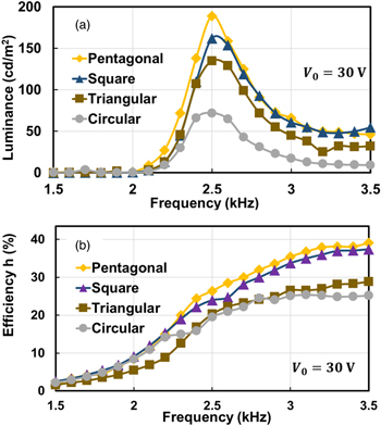
Fig. 9. (Color online) Luminance (a) and transmission efficiency η (b) versus driving frequency for different coil shapes.
Download figure:
Standard image High-resolution imageThe two coils are then displaced up to 50 mm, which length corresponds to the radius of the coils, along the line connecting the coil center and one of the corners. The results for the circular, triangular, square, and pentagonal coils are summarized in Fig. 10. Figure 10 shows the luminance of the four different coils only; the transfer efficiencies for this condition were in the same trend as the luminance, as seen in Figs. 8(a) and 8(b).
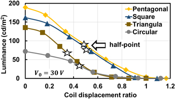
Fig. 10. (Color online) Luminance versus coil displacement ratio ρ for different coil shapes. At ρ = 1.0, displacement distance D of circular, triangular, square, and pentagonal coils are 53.5 mm, 70 mm, 55 mm, and 60 mm, respectively.
Download figure:
Standard image High-resolution imageFor all the displacement distances, the pentagonal coil circuit shows the highest EL brightness, and the highest transmission efficiency η accordingly. The displacement ratio ρ where the half luminance is obtained is 0.44 for the circular coil, 0.35 for the triangular coil, 0.50 for the square coil, and 0.47 cm for the pentagonal coil.
As a whole, the pentagonal coil is the most preferable in terms of peak luminance and immunity to coil displacement. The square coil also has good performance, showing only a little lower luminance than the pentagon coil at all displacement distances.
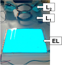
Figure 11 shows a photograph of the EL being driven by the WPT system. The circular solenoid coils are used as L1 and L2 in this picture.
Fig. 11. (Color online) WPT system using inorganic EL device as a load.
Download figure:
Standard image High-resolution image
5. Conclusions
We presented the experimental results on the effects of coil types and shapes employed for a WPT system using the inorganic EL as a load. The inorganic EL sample was operated with the WPT circuit at a significantly low supply voltage of 30 V, when the resonance condition is satisfied. The EL luminance over 150 m−2 was achieved for the WPT EL lighting system. Consequently, high voltage power cables, as well as high voltage ac power circuits, can be eliminated from the system.
Three different types of coils are compared to evaluate the EL luminance and the transmission efficiency with the WPT driving. Among all, the solenoid coil circuit presented the highest luminance when the coil displacement is zero. When the displacement distance becomes larger, the luminance of the solenoid coil becomes the lowest and the spider and the spiral coils show higher luminance.
Finally, the effects of coil shape were evaluated. Polygonal coils with different numbers of corners were prepared. The pentagonal coil presented the highest luminance and transmission efficiency at any displacement distance. Those for the circular coil were the lowest.
In conclusion, the WPT circuit is a simple and useful cordless lighting system for inorganic EL devices. Particularly, when an appropriately sized EL is employed, the additional capacitor C2 in this experiment can be eliminated, so that only two components are necessary for the secondary (load side) circuit, which makes the system much simpler.
The current results indicate the importance of the magnetic flux distribution and the coupling factor for each type and shape of the coil inductors L1 and L2 in the WPT circuits. Further analyses are being planned to investigate the relationship between the coil design and the transmission efficiency.
Acknowledgments
This work was supported by the Joint Research Center for Science and Technology of Ryukoku University.