
Abstract
This paper compares three different piston mode designs for temperature-compensated surface acoustic wave (TC-SAW) resonators using SiO2/LiNbO3 structure. It was shown that in rough approximation, phase shift given by extra elements for the piston mode operation is determined by the total mass of extra elements and SiO2 which overlaid on piston region. The hammer head design without additional metal layers does not work properly due to the weaker impact of the extra elements when the SiO2 layer is thick. On the other hand, piston mode designs using metal dots or stripes are effective to suppress the transverse mode resonances even when the SiO2 layer is thick. Although larger metal thickness is preferable for the wideband operation, it also makes the split of main resonance. Thus, the optimal metal thickness can be found from this trade-off, and then the optimal metal width can be found to achieve good transverse mode suppression.
Export citation and abstract BibTeX RIS
1. Introduction
Temperature-compensated (TC) surface acoustic wave (SAW) devices are widely used in current mobile phones. One type of TC technology is the use of layered substrate structures in which a piezoelectric LiTaO3 (LT) or LiNbO3 (LN) layer is bonded to a substrate with a small coefficient of thermal expansion, such as silicon or sapphire. 1–9) Another one is the deposition of a SiO2 layer on interdigital transducers (IDTs) and reflectors on an LT/LN substrate. 10–25) The incredible SAW structure using an ultra-thin LT/LN layer can be regarded as a combination of these technologies. 26–30) Among them, SiO2 covered 128°YX-LN is most commonly used as the TC-SAW structure. 12,13,21–25)
In this configuration, one of the most important design goals is the suppression of transverse mode resonances. Now the "piston mode" technique is widely used for the suppression of transverse modes. The technique was first proposed for bulk acoustic wave devices 31) and then applied to SAW devices. 32–36) Solal et al., proposed the use of the "hammer head" structure placed at the end of IDT. 32) Its variations are deposition of metal dots above the IDT aperture ends 35,36) and metal stripes on the SiO2 layer surface. 33) These extra elements serve as phase shifters to make the aperture edges behave mechanically free for lateral SAW propagation.
The authors compared the applicability of these piston mode techniques for TC-SAW resonators on 131°YX-LN with SiO2 overlay. 37) This paper is an extended version of Ref. 37, and is aimed at discussing the applicability of these three-piston mode techniques systematically and more in detail. The three structures are designed by the three-dimensional (3D) finite element method (FEM), and it is shown how design parameters affect spurious responses and how each structure should be designed.
Roughly speaking, the phase shift is mostly determined by the total mass of extra elements and SiO2 which overlaid on the piston region. The applicability of the "hammer head" design is limited due to the weaker impact of the extra elements when the SiO2 layer is thick. Namely, transverse modes can be suppressed only when the SiO2 layer is thin. In contrast, the designs using metal dots or stripes can work well even when the SiO2 layer is thick.
It should be noted that the deposition of metal dots or stripes makes the main resonance split in two due to the mass loading. Thus, their thickness should be limited so that the split of the main resonance is negligible. Since thicker is preferable in principle, the thickness should be set close to this limitation. Then required width of metal dots or stripes will be determined to give sufficient transverse mode suppression.
It is interesting to note that the required width of metal dots is about two times larger than that of stripes for the given metal thickness. This can be understood due to the difference in the metallization ratio (MR) in the extra elements.
2. Structural design and simulation
Figure 1 shows the cross-sectional view of the SiO2/131°YX-LN structure used for the 3D FEM analysis. Cu is chosen as the IDT material, and the top surface of the covering SiO2 layer is assumed to be flattened. The perfect matching layer (PML) is given at the bottom surface of LN. No additional loss is included in the simulation. Table I shows its design parameters.
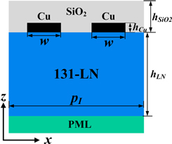
Fig. 1. (Color online) Cross-sectional view of the resonator structure under concern. 37)
Download figure:
Standard image High-resolution imageTable I. Used structural parameters.
| Parameters | Value |
|---|---|
| IDT period pI | 1.9 μm |
| LN Thickness, h LN | 10 μm |
| Cu electrode thickness, h Cu | 5%pI |
| SiO2 thickness, h SiO2 | 30%pI |
| Electrode width, w | 0.25pI |
| Aperture | 16pI |
| Gap length | pI |
| Busbar width | 3pI |
| Metallization ratio (MR) | 0.5 |
Figure 2 shows the top view of four IDT patterns used in this discussion. PMLs are given to the left and right boundaries while the periodic boundary conditions are applied to the top and bottom boundaries. Figure 2(a) shows the basic structure without the extra elements (design A), and Fig. 2(b) shows a piston mode design (design B) with widened IDT electrode ("hammer head") edges. In the design shown in Fig. 2(c) (design C), Cu stripes are deposited on the top surface of the SiO2 layer while Cu dots are added to the IDT aperture edges in the design shown in Fig. 2(d) (design D) on the top of IDT electrode.

Fig. 2. (Color online) Top view of four IDT patterns used for the discussions. 37)
Download figure:
Standard image High-resolution imageFigure 3 shows admittance (Y) and conductance (G) of these designs calculated by the 3D FEM. Results giving the best transverse mode suppression are shown for designs B, C and D. When the piston design is not applied (design A), transverse mode resonances are clearly seen above the main resonance [see Fig. 3(a)].

Fig. 3. (Color online) Calculated Y and G of four designs. 37)
Download figure:
Standard image High-resolution imageFigure 3(b) shows the calculated Y and G of design B when the MR and length of hammer heads are set at 0.9 and 0.53 pI, respectively. Transverse modes could not be suppressed well using this design. Its reason will be discussed in Sect. 3.1.
Figure 3(c) shows the calculated Y and G of design C, where the thickness hstripe and width wstripe of Cu stripes are set at 0.037 pI and 0.13 pI, respectively. It is seen that the transverse mode resonances are well suppressed.
Figure 3(d) shows the calculated Y and G of design D, where the thickness hdot and width wdot of Cu dots are set at 0.037 pI and 0.32 pI, respectively. Transverse mode resonances are well suppressed also for this case.
3. Discussions
3.1. Piston B design
Figure 4 shows the variation of Y of design B with hSiO2 when the metallization ratio and length of hammer heads are set at 0.9 and 0.53 pI, respectively. It is seen that transverse resonances can be suppressed to some extent when hSiO2 is reduced to 0.08pI. Further calculation indicated that good transverse resonance suppression can be achieved when hSiO2 is reduced to 0.06pI after slight MR reduction.
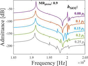
Fig. 4. (Color online) Variation of Y of deign B with thickness of SiO2 layer.
Download figure:
Standard image High-resolution imageThis may be explained by the fact that larger hSiO2 gives deeper SAW energy penetration to the SiO2 layer and makes impact of the extra elements weaker. This means applicability of the design B is limited intrinsically to cases when the SiO2 layer is thin under comparison with designs C and D.
3.2. Piston C design
Figure 5(a) shows the variation of Y of design C with hstripe when wstripe is fixed at 0.13 pI. It is seen that although transverse modes are well suppressed when hstripe = 0.037 pI, ∣Y∣ of the main resonance is small. This height reduction is due to split of the main resonance to two instead of the Q reduction. In fact, this additional resonance can be seen clearly below the main resonance when hstripe > 0.037 pI.

Fig. 5. (Color online) Variation of Y of the design C with width and thickness of the Cu stripes.
Download figure:
Standard image High-resolution imageFigure 6 shows the total displacement at the two spurious peaks m1 and m2 in Fig. 5(a). Clear energy concentration, i.e. resonance, is seen near the Cu stripe region. Existence of two resonances and asymmetry of the resonance pattern are due to intrinsic anisotropy in LN. Their frequencies do not change with wstripe so much. On the other hand, a larger hstripe is preferable for transverse mode suppression for a wide frequency range as shown in Fig. 5(a) when hstripe is set from 0.016pI to 0.037pI. This is because the transmission phase in the phase shifters changes rapidly with the frequency near their resonance. Thus hstripe should be set to close to this limit, namely 0.037 pI when hSiO2 is set at 0.3pI.
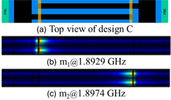
Fig. 6. (Color online) Total displacement of the design C.
Download figure:
Standard image High-resolution imageFigure 5(b) shows the variation of Y of the design C with wstripe when hstripe is fixed at 0.037 pI. The split of main resonance becomes obvious when wstripe is larger than 0.14 pI, and spurious resonances can be well suppressed when hstripe is circa 0.13 pI.
Figure 7 shows the variation of optimal wstripe giving the best transverse mode suppression with hstripe. Similar responses can be achieved even when wstripe is set a little longer (or shorter) when hstripe is set a little smaller (or larger).
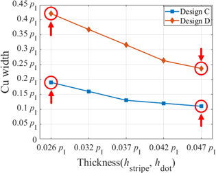
Fig. 7. (Color online) Variation of optimal Cu width with Cu thickness.
Download figure:
Standard image High-resolution imageFigure 8 shows the admittance curves of corner conditions in Fig. 7. Figure 8(a) shows variation of Y of the design C with wstripe when hstripe is fixed at 0.026 pI, it can be seen that optimal wstripe should be 0.19 pI which has been shown in Fig. 7. Figure 8(b) also shows the optimal wstripe of design C should be 0.11 pI when hstripe is fixed at 0.047 pI.
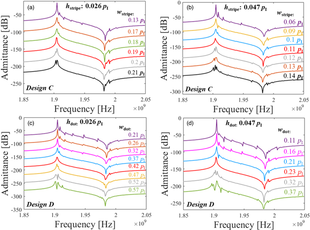
Fig. 8. (Color online) Variation of Y of the design C and design D with the width of Cu stripes and dots.
Download figure:
Standard image High-resolution image3.3. Piston D design
The procedure for the Piston D design is quite similar to the Piston C design described above.
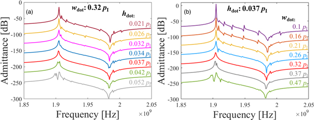
Figure 9(a) shows the variation of Y of design D with hdot when wdot is fixed at 0.32 pI. The split of main resonance can be also seen clearly for this case when hdot > 0.037 pI. This additional resonance is due to a SAW resonance of the Cu dot region. Thus, we can conclude that hdot should be set close to 0.037 pI when hSiO2 is set at 0.3pI.
Fig. 9. (Color online) Variation of Y of the design D design with width and thickness of Cu dots.
Download figure:
Standard image High-resolution image
Figure 9(b) shows the variation of Y of design D with wdot when hdot is set at 0.037 pI. It is seen that most of all spurious resonances disappear and a clean response is achieved by setting wdot to 0.32 pI.
In Fig. 7, variation of optimal wdot with hdot is shown also for this case. The variation is similar to Design C.
Figure 8(c) shows the optimal wdot of the design D should be 0.42 pI when hdot is fixed at 0.026 pI while Fig. 8(d) shows the optimal wdot of the design D should be 0.23 pI when hdot is fixed at 0.047 pI, the variation of optimal wdot with hdot is shown in Fig. 7.
Note that the optimal wdot (design D) is about two times larger than the optimal wstripe (design C) for given Cu thickness. This can be understood due to the fact the metal dots cover only IDT fingers in this case while the metal stripes cover also gaps between fingers.
These results confirm that the phase shift given by the extra elements is mostly determined by the total mass of extra elements and SiO2 which is overlaid on the piston region in rough approximation.
4. Conclusions
This paper compared three different piston mode designs for the TC-SAW resonator, and their design procedures were explained in detail.
It was shown that in rough approximation, phase shift given by the extra elements is determined by the total mass of extra elements and SiO2 which overlaid on piston region. The hammer head design without additional metal layers does not work properly due to the weaker impact of the extra elements when the SiO2 layer is thick. On the other hand, piston designs using metal dots or stripes are effective for the transverse mode suppression even when the SiO2 layer is thick.
Although larger metal thickness is preferable for wideband operation, it also causes another resonance just below the main resonance. Thus, the optimal metal thickness can be estimated from this trade-off, and then the optimal metal width can be found to achieve good transverse mode suppression for the determined metal thickness.
In practice, other factors such as other spurious responses and fabrication tolerance must be also taken into account. The authors believe that the design procedures given in this paper will be helpful even for such cases.
Acknowledgments
This work was supported in part by the Research Project under Grant A1098531023601318 and in part by the National Natural Science Foundation of China and the China Academy of Engineering Physics under Grant U1430102.