
Abstract
Recently, remarkable developments in contact-less manipulation methods using ultrasonic transducer arrays have been reported. Ultrasonic non-contact manipulation enables precise control of small objects without contamination; therefore, it is expected to have a wide range of applications. In this paper, we present a novel approach for the stable non-contact pick-up of small particles from a rigid stage using a hemispherical ultrasonic transducer array. We achieved stable pick-up by employing adaptive phase and amplitude control against the distance from the reflection stage.
Export citation and abstract BibTeX RIS

Content from this work may be used under the terms of the Creative Commons Attribution 4.0 license. Any further distribution of this work must maintain attribution to the author(s) and the title of the work, journal citation and DOI.
Acoustic non-contact manipulation enables the precise control of small objects without contamination. Acoustic radiation force can also be used to manipulate particles of various sizes and materials. 1–4) For non-contact manipulation via acoustic radiation force in air, Langevin transducers for ultrasonic emitters have been mainly used. 5–7)
Recently, remarkable developments in contact-less manipulation methods using ultrasonic transducer arrays have been reported. Unlike the Langevin oscillator, a transducer array can be operated within a small system. 8) A method of facing ultrasonic transducer arrays has been proposed; this approach enables three-dimensional manipulation. 9) Furthermore, holographic techniques 10,11) have been applied to acoustic levitation. An advanced method for manipulating objects in a three-dimensional space has been proposed; this approach entails optimizing the phase delay of each ultrasonic transducer in the array, and it enables three-dimensional manipulation, even when using a single-sided ultrasonic transducer array. 12) However, when employing these methods to manipulate a single small object, it is necessary to first use metal or plastic tweezers to place the object at the focal point created by the transducer array. In other words, a contact operation is required at the beginning of the non-contact operation. Hence, to achieve a completely non-contact operation for an object present on the stage, the object should be picked up by the sound waves themselves. However, a major concern when picking up objects using the acoustic radiation force is the reflection effect caused by the stage. Because the sound field is disturbed by this reflection, it is not possible to hold the object in a stable manner. To solve this problem, our research group previously proposed an approach involving the use of a stage with low acoustic reflection, representing the first step toward a method for the pick-up of objects with a transducer array. 13)
Another feasible approach is to use the reflected sound; this approach has received significant research attention. 14,15) It is well known that a particle levitates at the nodes of a standing wave. Consequently, altering the frequency of the signal of transducers enables the transfer of a particle. 14) However, it remains unknown whether this technology is capable of picking up particles in air. Recently, a contact-less pick-up method using inverted near-field acoustic levitation with an ultrasonic Langevin transducer was proposed; 16) however, this method is incapable of manipulating objects.
In this background of aerial acoustic manipulation, non-contact pick-up from a rigid stage using a hemispherical ultrasonic transducer array was proposed in our previous work. 17) In this study, we first succeeded in picking up a small object from a stage with acoustic reflection by applying blocking and phase and amplitude control to the excitation of a transducer array.
Improving the stability remains a research task for the transport of particles. We previously proposed an approach for improving stability. 18) In the present study, we further developed this method and established an approach involving the use of two types of phase and amplitude control adaptively. This approach can pick up and hold particles in a stable manner.
We developed a multi-channel hemispherical ultrasonic transducer array for adaptively controlled non-contact manipulation. We used 180 ultrasonic transducers (Murata MA40S4S), each having a diameter of approximately 10 mm and a center frequency of 40 kHz. Figure 1(a) shows the arrangement of the array and the axis of coordinates. The hemispherical array was divided into 7 segments, and each segment was driven independently, as shown in Fig. 1(b). Each segment was further divided into two halves for two types of excitation methods, resulting in a total of 14 channels. These segments were individually controlled as shown in Fig. 1(b). Figure 1(c) shows a simplified diagram of the driving system used to pick up particles. We used a personal computer to control two digital-analog (D/A) converters (RME FIREFACE 802 and Babyface Pro FS) connected in parallel. The power amplifier used was CROWN CT8150. Supplementary file 1 (available online at stacks.iop.org/JJAP/61/SG8004/mmedia) shows a photograph of the hemispherical ultrasonic transducer array.

Fig. 1. (Color online) (a) Transducer array arrangement and the axis of coordinates. (b) Schematic of the 14-channel configuration (the color represents the segments controlled independently) (c) a simplified diagram of the driving system for picking up a particle.
Download figure:
Standard image High-resolution imageIt is known that, when driving a hemispherical array half of whose transducers are mounted with reverse polarity, an acoustic trap is generated at the center of the array. 13,19) In the proposed method, we divide the transducers in the array into spherical segments capable of individual control (see Fig. 1(b)). To optimize the signals of each segment, we employ the method derived from the sound reproduction technique 20) with an inverse filter, as follows:
If there are  transducers in the jth segment, we define variable
  as follows:

where  is the propagator, and
  is the number of transducers. The sound reflections are calculated using the image-source method and added to the propagator, which is defined as

where  is a constant defined by the transducer power,
  is a zeroth-order Bessel function of the first kind,
  is the wavenumber,
 is the radius of the piston,
  is the distance between the transducer and control points, and
  is the angle between the normal to the transducer and the control points. Thus, we define the matrix
  as follows:

where  and t are the total number of control points and spherical segments, respectively. Moreover, we define the target wave field as
 ![$H=\left[{h}_{1},{h}_{1},{h}_{2}\cdots ,{h}_{c}\right].$](https://content.cld.iop.org/journals/1347-4065/61/SG/SG8004/revision2/jjapac51c4ieqn14.gif) We calculate the filter coefficient
We calculate the filter coefficient ![$W=\left[{w}_{1},{w}_{1},{w}_{2}\cdots ,{w}_{t}\right]$](https://content.cld.iop.org/journals/1347-4065/61/SG/SG8004/revision2/jjapac51c4ieqn15.gif) by solving the following equation:
by solving the following equation:

We solve this equation using the weighted least squares method with

where * denotes the Hermitian transpose and  is the weight. Filtering the signal of each channel using the filter coefficient
  we optimize the phase and the amplitude. We selected the target wavefield
  that was formed at the center when a spherical ultrasonic transducer array was driven half part of the opposite phase. This wavefield only generated an acoustic trap at the center. The target wave field was calculated using a numerical simulation based on geometrical acoustics. We slide up this wavefield to translate a particle. We placed control points in a grid and added a large weight to the surrounding trap point.
We divided the spherical array into two segments in the vertical plane (see Fig. 1(b)) to switch the opposed-phase and in-phase excitations. During the opposed-phase excitation, we reversed the polarity of one of the excitations. Figure 2 shows some cases of the acoustic pressure fields of the in-phase and opposed-phase excitations calculated through numerical simulations. Figure 3 shows some cases of the phase patterns of the in-phase and opposed-phase excitations. In-phase excitation makes a sound field look like a standing wave (Figs. 2(a) and 2(b)), and can stably levitate near a rigid stage. When slightly levitating a particle from a rigid stage, we used the segments at the top of the array. Opposed-phase excitation can levitate and hold a particle up to the center of the array (Figs. 2(c) and 2(d)). Therefore, adaptively switching between opposed-phase and in-phase excitations can enable robust non-contact picking up of a particle. The non-contact pick-up procedure can be described as follows:
- 1.
- 2.
- 3.
- 4.
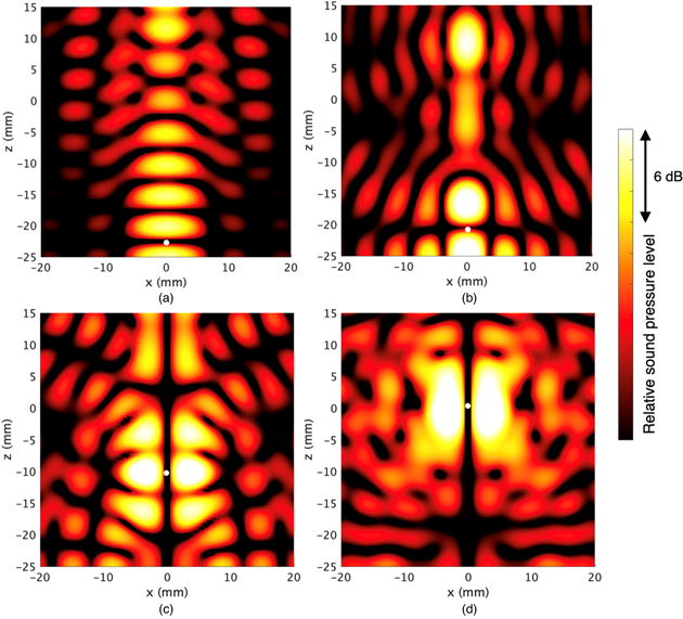
Fig. 2. (Color online) Wavefield on the vertical plane calculated via numerical simulations based on geometrical acoustics when capturing a particle. The rigid stage is at  mm. (a) Only using certain segments at the top of the array during in-phase excitation to hold a particle at
  (Step 1). (b) Using all segments of the array during in-phase excitation to hold a particle at
  mm (Step 2). (c) Using all segments of the array during opposed-phase excitation to hold a particle at
  mm (Step 3). (d) Driving all segments of the array during opposed-phase excitation by a single signal to maintain the particle (Step 4).
Download figure:
Standard image High-resolution image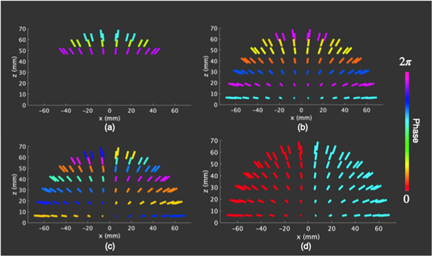
Fig. 3. (Color online) Color maps showing the phase of each transducer. (a) Only using certain segments at the top of the array during in-phase excitation to hold a particle at  mm (Step 1). (b) Using all segments of the array during in-phase excitation to hold a particle at
  mm (Step 2). (c) Using all segments of the array during opposed-phase excitation to hold a particle at
  mm (Step 3). (d) Driving all segments of the array during opposed-phase excitation by a single signal to maintain the particle (Step 4).
Download figure:
Standard image High-resolution imageWe performed the pick-up of a particle with a hemispherical ultrasonic transducer array. The target wave field calculated via the numerical simulation was realized using a spherical array comprising 360 transducers (including 180 transducers, as estimated by the mirror image method) driven at 40 kHz. The control points for the computation were set at 4 mm intervals, in a centered 25 mm range. Consequently, a total of 1331 target points were obtained. The weight coefficients were set according to a Gaussian function centered at the trap point.
As shown in Fig. 3(a), we used three segments at the top of the array to lift a particle. The rigid reflective stage was located 25 mm below parallel to the array. We employed a polystyrene sphere with a diameter of approximately 1 mm as the target object.
We used a personal computer to control the input signals, convert the digital signals to analog signals with an RME D/A converter, and amplify the signals using the CROWN amplifier as an experimental system (see Fig. 1(c)). The signal amplitude ranged from 0 to 18.5 V (peak-to-peak).
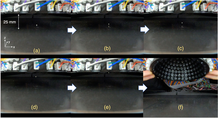
Figure 4 and supplementary file 2 present the experimental results. As is evident, particles could be picked up and held. The adaptive use of in-phase and opposed-phase excitations enables stable pick-up. By designing the trap point appropriately, the instability when switching between the in-phase and opposed-phase excitations can be eliminated. By exciting the upper segment of the array, an acoustic trap can be appropriately generated within a small area to ensure that the particles are suspended near the stage.
Fig. 4. (Color online) Photograph highlighting the picking up of a particle on the rigid stage: (a) successful picking up; (c)–(d) upward motion; and (f) successfully maintaining the particle.
Download figure:
Standard image High-resolution image
It should be noted that it is impossible to lift a particle to the array position using only the in-phase excitation method because the range of motion of the nodes is relatively narrow. In addition, we could selectively pick up the particles; moreover, if the particles were more than 1 cm apart, we could pick up the targeted particle.
We developed a multi-channel hemispherical ultrasonic transducer array capable of switching between the two excitation modes. The proposed method can achieve stable pick-up from a rigid stage, as well as ensure stable retention of the particles. In future research, we plan to introduce an embedded system to make the system small and simple. We will plan to install an FPGA to increase the number of channels and attempt to pick up droplets and large particles.
Acknowledgments
This work was partially funded by The Murata Science Foundation.