
Abstract
Multi-user underwater acoustic communication is expected to support efficient and reliable underwater exploration by networking devices in oceans. However, crosstalk occurs when multiple devices emit signals simultaneously. To address this issue, we previously proposed an aplanatic compound eye lens that had the potential to achieve space-division multiple access, but the lens had a complex shape. In this paper, we designed a simple-shape lens consisting of a concave meniscus and having a hemispherical incident surface. Multi-user communication using lenses was simulated. The results showed that the proposed hemispherical lens had almost the same communication quality as the existing aplanatic compound eye lens.
Export citation and abstract BibTeX RIS
Recently, the cooperative use of multiple underwater vehicles has attracted attention for their ability to make ocean exploration more efficient. Underwater acoustic (UWA) communication is a means of establishing an underwater mobile network. However, the establishment of a UWA network is still challenging due to issues in both physical and network layers. In the physical layer, the UWA channel has large delay and Doppler spreads, and countermeasures, such as orthogonal signal-division multiplexing, have been proposed. 1–8) In the network layer, the UWA channel has a large delay and the available bandwidth is severely limited. Hence, the collision of packets on a shared single channel can degrade performance. To address this, multiple access techniques (e.g. time-, frequency-, code-, or space-division multiplexing) or packet scheduling algorithms have been considered. 9–15)
As an alternative, we previously proposed a space-division multiplexing UWA communication system using acoustic lenses and mirrors. 16–18) The use of acoustic lenses has the potential to realize a simple UWA network because it can transmit and receive multiple beams simultaneously without the need for complicated circuits. Aplanatic compound eye acoustic lenses with partitions have been found to be effective in realizing multi-user communication. 19) However, the lens had a complex shape and faced high underwater resistance. To install an acoustic lens on devices such as AUV, the lens must have a simpler shape.
In this paper, we design a hemispherical compound eye lens consisting of concave meniscus lenses to simplify the shape and reduce underwater resistance. 20) We also design a transducer array to match the locations of focal points using a wave propagation simulation. We then evaluate the quality of UWA communication using the proposed hemispherical lens in comparison with that using the existing aplanatic compound eye lens designed with the same parameters as the hemispherical lens.
The meniscus lens is shown in Fig. 1. The first surface is spherical with a radius of r. The second surface is aspherical to correct the spherical aberration and is designed using an optimization technique. The aperture of the second surface is larger than that of the first surface D, because the incident rays are refracted in the diffusing direction. Refractive index n, thickness d, and focal length f are initially determined. The optical path length through the center of each lens, l0, is expressed as,

The incidence point P1(z1, y1) is on the hemisphere and is expressed as,


The refraction angle β on P1 can be calculated by Snell's law as,

Therefore, the refracted acoustic ray can be expressed as,

The ray expressed by Eq. (5) is again refracted at point P2(z2, y2) on the second surface. The ray then arrives at the focal point F(f − r, 0). The optical path length of this ray, l, can be expressed as,

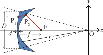
Fig. 1. (Color online) Schematic view of concave meniscus lens.
Download figure:
Standard image High-resolution imageThe spherical aberration can be corrected under the condition of l = l0. However, it is challenging to analytically determine the position of P2. Therefore, we slightly change z2 within a certain range to find the condition of l = l0. As long as l = l0 holds, the calculation will be conducted sequentially from y1 = 0 to y1 = D/2. If l = l0 does not hold, the calculation is terminated.
We initially choose 180° as the angle of view of the whole lens, 30° as the angle of view of each lens segment, and 6 as the number of meniscus lenses. The radius of the first surface r = 400 mm, the refractive index n = 0.56, and the central thickness d = 5 mm. Thus, the shape of the lens would depend on the focal length f. Several shapes of the lens are shown in Fig. 2. The ratio of focal length f to aperture D was varied from 0.5 to 1.0 at intervals of 0.1. The black dotted line indicates the separation line between adjacent meniscus lenses. The longer the focal length f is, the larger the aperture of the second surface becomes, because the calculation continues under the condition l = l0. The ratios f/D = 0.5, 0.6, and 0.7 are not sufficient because their second surfaces, indicated by the blue lines, do not cross the separation line, and those of f/D = 0.9 and 1.0, indicated by the green lines, are far beyond the separation line. Therefore, we decided to use f/D = 0.8.

Fig. 2. (Color online) Examples of concave meniscus lens designed for several ratios of focal lengths and diameter f/D.
Download figure:
Standard image High-resolution imageThe sound propagation was calculated using the two-dimensional finite difference time domain (2D FDTD) method. The discretization widths were 0.25 μs in time and 1 mm in space. The dimensions of the simulation field are −500 mm ≤ z ≤ 500 mm and −500 mm ≤ y ≤ 500 mm. The outer boundary is Higdon's second-order nonreflecting boundary. The parameters of the media are shown in Table I. A line source is located on z = −495 mm. A chirp signal (center frequency, 37.5 kHz; bandwidth, 5 kHz) was emitted from the line source. The angle of incidence θ was varied from −15° to 15° at intervals of 1°. The focal points of the meniscus lens and those of an aplanatic lens designed with the same parameters as the meniscus lens were calculated.
Table I. Parameters of 2D FDTD simulation.
| Medium | Sound speed (m s−1) | Density (kg m−3) | Attenuation rate (Np m−1) |
|---|---|---|---|
| Water | 1500 | 1000 | 0 |
| Lens (acrylic resin) | 2700 | 1140 | 1.4 |
| Polyurethane | 1000 | 1190 | 13 |
The calculated focal points of the two lenses are shown in Fig. 3(a). The focal plane of the meniscus lens is almost straight, whereas that of the aplanatic lens is curved. Thus, we designed a transducer for the aplanatic lens by curve fitting using a parabola. The arrangements of the hemispherical and the aplanatic compound eye lenses with the transducers, partitions, and backing materials are shown in Figs. 3(b) and 3(c). Polyurethane is intended to be used for the partitions and the backing materials. Comparison of the lens shapes shows that the hemispherical lens has a simpler and thinner shape.

Fig. 3. (Color online) Shapes of the focal points and schematic view of simulation fields: (a) calculated focal points and arrangement of fitted transducers, (b) arrangement of the aplanatic compound eye lens, and (c) arrangement of the hemispherical compound eye lens.
Download figure:
Standard image High-resolution imageSimulations were performed to evaluate the quality of UWA communication using the designed lens and the transducer array. We simulated the reception of sound waves from two directions, which were θ1 and θ2, to generate crosstalk. The impulse responses were calculated by a cross-correlation function between the transmitted and received signals, from θ1 = −90° to θ1 = 90° at intervals of 1°. Then the received communication signals on each transducer were calculated by convoluting a communication data block and the impulse response. The communication signals were calculated by modulating a data block that consisted of a training sequence of 100 bits and a message sequence of 1000 bits by bi-phase shift keying and up-converting the signal to the frequency of 37.5 kHz (signal bandwidth, 5 kHz). The received communication signals from θ2 were calculated using the same method. Crosstalk signals were generated by adding these two received communication signals from θ1 and θ2. The crosstalk signals were equalized by a decision feedback equalizer using recursive least squares (feedforward, 51 taps; feedback, 50 taps; forgetting factor, 0.999). Finally, the communication quality was evaluated by the output signal-to-noise ratio (OSNR) and bit error rate (BER) of each azimuthal difference ∣θ1 − θ2∣. UWA communication using the proposed hemispherical compound eye lens was compared with that using the existing aplanatic compound eye lens and that using the transducer array of the hemispherical lens (no lens or partition).
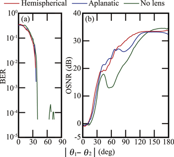
The BERs are shown in Fig. 4(a). Each BER becomes smaller as the azimuthal difference increases. Areas with no lines indicate that no errors have occurred. Since there is no error in the area above 90°, that area is omitted. The BERs of the hemispherical and the aplanatic compound eye lenses almost agree and become error-free above ∣θ1 − θ2∣ = 35° and 36°, respectively. This result makes sense because the lens segment has an angle of view of 30°. The BER of the transducer array becomes error-free at ∣θ1 − θ2∣ = 72°. Thus, the use of the lens improved the azimuthal difference to minimize crosstalk by more than 30°.
Fig. 4. (Color online) Results of communication simulation: (a) relationships between BERs and azimuthal difference and (b) relationships between OSNRs and azimuthal difference.
Download figure:
Standard image High-resolution image
OSNRs of UWA communication are shown in Fig. 4(b). They are almost identical below ∣θ1 − θ2∣ = 30°. The OSNR of UWA communication using the aplanatic compound eye lens is the highest among the three conditions when 38° ≤ ∣θ1 − θ2∣ ≤ 68°. Then, that using the hemispherical is the highest when 68° < ∣θ1 − θ2∣ ≤ 140°, and that using no lens is the best when 140° < ∣θ1 − θ2∣. These results can be discussed as follows. For 38° ≤ ∣θ1 − θ2∣ ≤ 68°, the aplanatic lens-correcting spherical and coma aberrations focused better than the hemispherical lens-correcting spherical aberration only and showed better-quality UWA communication. However, as the azimuthal difference increased, the signals from different directions could be easily separated. Thus, the attenuation in the lens became more important than the focusing characteristic of the lens. For 68° < ∣θ1 − θ2∣ ≤ 140°, the hemispherical lens having a thinner shape than the aplanatic lens showed better-quality UWA communication, and for 140° < ∣θ1 − θ2∣, quality of communication became rather better without the lens.
In this paper, we designed a hemispherical compound eye lens consisting of meniscus lenses. We evaluated the quality of UWA communication using the proposed lens by simulation in comparison with the existing aplanatic compound eye lens. As a result, though the hemispherical lens showed low-quality UWA communication at specific incidence angles, it achieved crosstalk-free communication of the same quality as the aplanatic compound eye lens. Hence, the hemispherical lens was found to effectively reduce underwater resistance and is suitable for installation on AUVs because of its simple shape.
Acknowledgments
This work was supported by JSPS KAKENHI Grant No. 19H02351.