

Abstract
The propagation and resonance properties of longitudinal leaky surface acoustic waves (LLSAWs) on bonded structures consisting of a quartz (Qz) thin plate and a Qz support substrate with different Euler angles were investigated theoretically. By using both an X-cut Qz thin plate and a Qz support substrate with optimal Euler angles, we obtained LLSAWs with a larger coupling factor, a smaller attenuation, and a lower temperature coefficient of frequency than those on a single Qz substrate. Furthermore, from the resonance properties simulated by the finite element method, the bonded structures were found to exhibit a large admittance ratio and a high quality factor, which could not be obtained when using a single Qz substrate; the bandwidth, however, was as small as 0.016%–0.086%.
Export citation and abstract BibTeX RIS
1. Introduction
High-performance surface acoustic wave (SAW) devices with large bandwidth (BW), high frequency, high quality (Q) factor, and small temperature coefficient of frequency (TCF) are required for fifth-generation (5G) and next-generation communication systems. Recently, many studies have been reported related to high-performance SAW devices. 1–19) The SAW propagation modes suitable for high-frequency devices include a shear horizontal (SH) leaky SAW (LSAW) and a longitudinal LSAW (LLSAW) with relatively high phase velocity. However, an LSAW has inherent attenuation because it propagates while radiating a shear vertical (SV) bulk wave into the substrate. An LLSAW has also huge attenuation due to the radiation of SV and SH bulk waves. It is necessary to suppress bulk wave radiations to achieve high Q. When using a single piezoelectric substrate such as quartz (Qz), LiTaO3 (LT), or LiNbO3 (LN), it is difficult to simultaneously satisfy the above requirements including small attenuation. Recently, to satisfy such requirements, high-performance dissimilar-material bonded structures have been developed. 1,7–20) For instance, bonded structures comprising an LT or LN thin plate with a thickness of less than one wavelength and a Qz support substrate have been developed and the LSAWs and LLSAWs in these structures have been investigated. 13–19) A high-frequency resonator with an LN thin plate and a multilayered acoustic reflector with a SiO2/Pt layer have been realized by utilizing LLSAW with high velocity. 1)
It is difficult to bond of dissimilar-material structures owing to the difference between the linear expansion coefficients of the different materials. Previously, we theoretically clarified the conditions under which LSAWs with larger resonance than those of LT and LN can be obtained on a similar-material bonded structure consisting of a thin plate and a support substrate with different Euler angles. 21) Furthermore, we experimentally found that the attenuations on the free and metallized surfaces were simultaneously reduced by fabricating a 5°Y-cut X-propagating LN (5°YX-LN) thin plate bonded to a 64°YX-LN substrate. 22) We also theoretically found that the resonance properties of LSAWs on similar-material bonded substrates consisting of a Qz thin plate and a Qz support substrate with different Euler angles are larger than those on a single substrate. 23)
We theoretically investigated the propagation and resonance properties of LLSAWs on bonded structures comprising a Qz thin plate and a Qz support substrate, and found the conditions optimal for obtaining small attenuation and large resonance properties. 24) In this study, those properties were investigated in more detail using an analytical solution and a finite element method (FEM). Moreover, the causes of the small attenuation and large resonance properties of LLSAWs upon bonding with a similar-material substrate were examined.
2. Theoretical calculation of propagation properties
Figures 1(a) and 1(b) show theoretical analysis models. We analyzed a three-layer structure of air/quartz thin plate/quartz support substrate, where the propagation of LLSAWs was in the x1 direction and the substrate depth was in the x3 direction, and the amplitude and phase in the x2 direction were uniform. The analysis of an LLSAW with attenuation in this section was based on Yamanouchi's method, and Farnell and Adler's SAW propagation analysis method was used for a layered structure. 25,26) The material constants of quartz reported by Kushibiki et al. were used. 27) The electromechanical coupling factor (K2) was determined from the relation K2 = 2(vf−vm)/vf, where vf and vm are the phase velocities for the electrically free and metallized surfaces, respectively. TCF was calculated from the relation TCF = TCV−α, where TCV is the temperature coefficient of velocity and α sets the linear expansion coefficient in the propagation direction for the support substrate. For the TCF analysis, the temperature coefficient of the Al electrode was not taken into account because the optimum thicknesses of the Al electrode for the bonded structures are as thin as 0.005λ or less as described later.
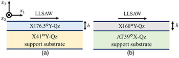
Fig. 1. (Color online) Theoretical analysis models of (a) X176.5°Y-Qz/X41°Y-Qz and (b) X160°Y-Qz/AT39°X-Qz structures.
Download figure:
Standard image High-resolution imageThe propagation properties of LLSAWs on the rotated Y-cut Qz have been reported. 28–30) For instance, AT-cut 0°X-propagating Qz [Euler angle: (0°,–54.7°,0°)] exhibits a high phase velocity of 5745 m s−1 and a small attenuation of less than 10–2 dB/λ; however, its K2 is 0.023%. 28) In general, wave energy is concentrated in the region with a slower phase velocity. The effect of the concentration of LLSAW energy in the thin plate can be expected by adopting a support substrate with a faster phase velocity than that of the thin plate. Therefore, in this study, for the Qz support substrate, Euler angles with high velocity for LLSAWs were chosen.
First, X-cut 41°Y-propagating Qz (X41°Y-Qz) was chosen as a support substrate because it has the highest phase velocity among X-cut Qz (X-Qz) materials [Euler angle: (90°,90°,ψ)] for LLSAWs. When a thin plate was chosen to be X176.5°Y-Qz, a small attenuation was obtained at a certain thin plate thickness. Figure 2(a) and 2(b) show the calculated propagation properties (phase velocity, attenuation, K2, and TCF) of LLSAWs on the X176.5°Y-Qz/X41°Y-Qz bonded structure [Fig. 1(a)]. The horizontal axis of these figures is the thin plate thickness h/λ normalized by the wavelength λ of LLSAWs. The attenuation shows a minimum value of 2.1 × 10⁻⁶ dB/λ at h/λ = 0.99. The K2 at h/λ = 0.99 is 0.14%, which is about 50 times higher than that (0.0026%) of the single X41°Y-Qz. Furthermore, the TCF at h/λ = 0.99 is –8.6 ppm which is about sevenfold lower than that (–58.9 ppm/°C of the single X41°Y-Qz.
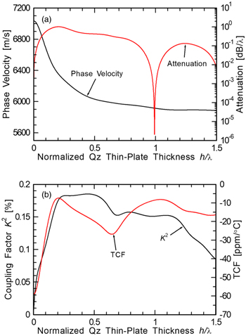
Fig. 2. (Color online) Calculated propagation properties of LLSAWs on X176.5°Y-Qz/X41°Y-Qz: (a) phase velocity and attenuation, and (b) K2 and TCF. 24)
Download figure:
Standard image High-resolution imageSecond, when AT39°X-Qz, which has a high phase velocity for LLSAWs, was used as a support substrate, the attenuation was found to be small with X160°Y-Qz bonded as a thin plate. Figures 3(a) and 3(b) show the calculated propagation properties of LLSAWs on the X160°Y-Qz/AT39°X-Qz bonded structure [Fig. 1(b)]. The attenuation shows a minimum value of 5.0 × 10⁻⁴ dB/λ at h/λ = 0.18. The K2 at h/λ = 0.18 is 0.15%, which is about 330 times larger that (0.00046%) of the single AT39°Y-Qz. Furthermore, the TCF at h/λ = 0.18 is 7.8 ppm/°C which is about sixfold lower than that (–42.4 ppm/°C of the single AT39°X-Qz. It was also found that zero TCF appeared at h/λ = 0.16, 0.60, and 0.72.
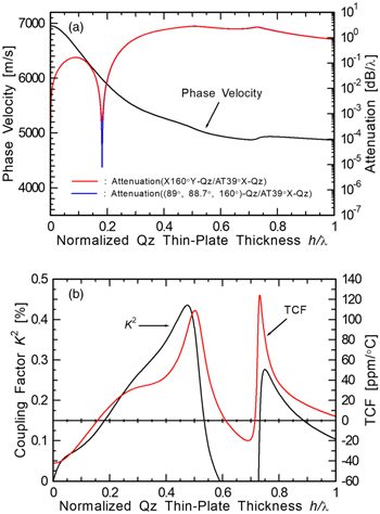
Fig. 3. (Color online) Calculated propagation properties of LLSAWs on X160°Y-Qz/AT39°X-Qz: (a) phase velocity and attenuation, and (b) K2 and TCF. 24)
Download figure:
Standard image High-resolution imageMoreover, the attenuation was further reduced by optimizing the Euler angle of the thin plate. For the (89°,88.7°,160°)-Qz/AT39°X-Qz bonded structure, an attenuation (7.9 × 10⁻⁶ dB/λ) smaller than that of X160°Y-Qz/AT39°X-Qz at h/λ = 0.18 was obtained, as shown in Fig. 3(a).
To investigate the cause of the reduced attenuation of LLSAWs, the component ratios in LLSAWs were calculated by deriving the interface potentials of longitudinal (L), fast-shear, slow-shear, and electrostatic wave components at the boundary between the thin plate and the support substrate. Figures 4(a) and 4(b) show the interface potentials of such components to X176.5°Y-Qz/X41°Y-Qz and (89°,88.7°,160°)-Qz/AT39°X-Qz bonded structures as functions of h/λ. The amplitudes were normalized interface potentials of electrostatic waves at each h/λ. The corresponding attenuation is also shown in these figures.

Fig. 4. (Color online) Normalized interface potentials of longitudinal, fast-shear, and slow-shear components, and attenuation for (a) X176.5°Y-Qz/X41°Y-Qz and (b) (89°,88.7°,160°)-Qz/AT39°X-Qz.
Download figure:
Standard image High-resolution imageThe interface potentials of the fast-shear and slow-shear components on X176.5°Y-Qz/X41°Y-Qz were both minimum at h/λ = 0.99, as shown in Fig. 4(a). For (89°,88.7°,160°)-Qz/AT39°X-Qz, a similar result was obtained at h/λ = 0.18, as shown in Fig. 4(b). Therefore, when the interface potentials of the fast-shear and slow-shear components were both minimum or small, this indicated that they were well separated from the L and electrostatic wave components. Then, the combination of the fast-shear and slow-shear components with the main component of LLSAWs weakened and the attenuation was almost zero. The attenuations of X176.5°Y-Qz(h/λ = 0.99)/X41°Y-Qz and (89°,88.7°,160°)-Qz(h/λ = 0.18)/AT39°X-Qz were 2.1 × 10⁻⁶ and 7.9 × 10⁻⁶ dB/λ, respectively. A small attenuation was obtained in the bonded structure where the interface potentials of the fast-shear and slow-shear components were both minimum. From the above results, the sufficient separation of the fast-shear and slow-shear components from the L and electrostatic wave components is considered to be an important factor that reduces the attenuation of LLSAWs.
3. Simulation of resonance properties
We simulated the resonance properties of an LLSAW in the case of forming an infinitely periodic interdigital transducer (IDT) with a period λ of 8.0 μm and an Al thin film (hAl: thickness) by FEM (Femtet, developed by Murata Software Co., Ltd.). A perfectly matching layer was placed at the bottom of the support substrate with a thickness of 10 λ.
First, to obtain a large admittance ratio and a high resonance Q factor by optimizing the Al thin film and thin plate thicknesses on the bonded structure, we investigated the dependence of the Al thin film thickness on each structure of X176.5°Y-Qz/X41°Y-Qz and (89°,88.7°,160°)-Qz/AT39°X-Qz without considering the mechanical losses Qm of Qz and Al. Figures 5 and 6 show the (a) admittance ratio and (b) resonance Q factor (Qr) for the normalized Al thin film thickness (hAl/λ) values of the X176.5°Y-Qz/X41°Y-Qz and (89°,88.7°,160°)-Qz/AT39°X-Qz bonded structures, respectively. The parameter in these figures is the normalized thin plate thickness h/λ, which was changed in the ranges of 0.96–1.01 in Fig. 5 and 0.17–0.19 in Fig. 6.
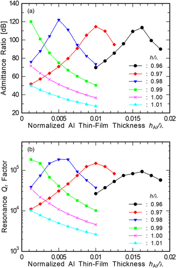
Fig. 5. (Color online) Al thin film thickness dependences of (a) admittance ratio and (b) resonance Qr factor on X176.5°Y-Qz/X41°Y-Qz.
Download figure:
Standard image High-resolution image
Fig. 6. (Color online) Al thin film thickness dependences of (a) admittance ratio and (b) resonance Qr factor on (89°,88.7°,160°)-Qz/AT39°X-Qz.
Download figure:
Standard image High-resolution imageFigures 5 and 6 show the Al film thickness at which the admittance ratio was maximum and the shift of the resonance Qr factor toward the larger thickness direction when h/λ was decreased. When h/λ was 0.98 for X176.5°Y-Qz/X41°Y-Qz, the maximum admittance ratio of 122 dB and the resonance Qr factor of 185 060 were obtained. On the other hand, when h/λ was 0.18 for (89°,88.7°,160°)-Qz/AT39°X-Qz, the maximum admittance ratio of 101 dB and the resonance Qr factor of 107 100 were obtained.
Then, from the above-mentioned Al thin film thickness dependences, Fig. 7 shows the simulated resonance properties of the X176.5°Y-Qz/X41°Y-Qz (h/λ = 0.98, hAl/λ = 0.005) and (89°,88.7°,160°)-Qz/AT39°X-Qz (h/λ = 0.18, hAl/λ = 0.00125) bonded structures with optimal Al thin film and thin plate thicknesses without considering Qm of Qz and Al. Shimizu et al. reported experimentally that an LSAW resonator using LST-cut Qz exhibited a resonance Q factor of 22 000 at 182 MHz.
31) From the reported Q factor, the resonance properties on those structure with considering Qm = 20 000 (1/Qm = 5  10–5) of Qz were also simulated and are also shown in Fig. 7. The resonance property of a single X176.5°Y-Qz (hAl/λ = 0.005) is also shown in Fig. 7. The horizontal axis of Fig. 7 shows the phase velocity v converted from the frequency f using the relation v = fλ. As shown in Fig. 7, it was found that a steep and large resonance for LLSAWs can be obtained by utilizing the similar-material bonded structures, whereas a small resonance appeared for a single Qz.

Fig. 7. (Color online) Simulated resonance properties of LLSAWs on a single Qz substrate, X176.5°Y-Qz/X41°Y-Qz, and (89°, 88.7°, 160°)-Qz/AT39°X-Qz. 24)
Download figure:
Standard image High-resolution imageTable I shows the simulated admittance ratio, fractional BW, resonance Qr factor, and anti-resonance Qa factor of LLSAWs for the similar-material bonded structures with and without Qm. It was also found that a large resonance can be obtained for X59°Y-Qz with a thin plate and an X41°Y-Qz support substrate. The simulated results of this X59°Y-Qz(h/λ = 0.40)/X41°Y-Qz bonded structure are also shown in Table I. The X176.5°Y-Qz/X41°Y-Qz showed the largest admittance ratio (61 dB with Qm) and the largest Qa (20 000 with Qm) the among the bonded structures considered. The largest Qa was saturated to the assumed Qm, whereas the Qa was simulated to be 740 880 without Qm. (89°,88.7°,160°)-Qz/AT39°X-Qz showed a 4 dB larger admittance ratio (57 dB with Qm), a higher Qr (17 040 with Qm), and a higher Qa (15 630 with Qm) than X160°Y-Qz/AT39°X-Qz.
Table I. Simulated resonance properties.
| 1/Qm | Admittance ratio [dB] | Fractional BW [%] | Qr | Qa | |
|---|---|---|---|---|---|
| X59°Y-Qz(h/λ = 0.40) /X41°Y-Qz | 0 | 78 | 0.016 | 216 700 | 288 980 |
| 5.0 × 10⁻⁵ | 32 | 0.017 | 18 450 | 19 300 | |
| X176.5°Y-Qz(h/λ = 0.98) /X41°Y-Qz | 0 | 122 | 0.086 | 185 060 | 740 880 |
| 5.0 × 10⁻⁵ | 61 | 0.086 | 18 050 | 20 000 | |
| X160°Y-Qz(h/λ = 0.18) /AT39°X-Qz | 0 | 75 | 0.070 | 46 900 | 46 900 |
| 5.0 × 10⁻⁵ | 53 | 0.083 | 13 880 | 11 910 | |
| (89°,88.7°,160°)-Qz(h/λ = 0.18) /AT39°X-Qz | 0 | 101 | 0.083 | 107 100 | 375 200 |
| 5.0 × 10⁻⁵ | 57 | 0.083 | 17 040 | 15 630 |
Since the optimum thicknesses of the Al electrodes for these bonded structures are as thin as 0.005λ or less, it is necessary to adjust the Al thin film thick so that the Al electrodes possess appropriate resistance when the LLSAW resonator will be actually fabricated. The simulated fractional BWs of these structures ranged from 0.016% to 0.086%. These values are much smaller than that required for the 5G and next-generation communication systems. The construction of a filter with a large BW and steep cutoff characteristics can be expected by combining the bonded structure with a ceramic LC filter having broad cutoff characteristics. The expected concrete method is as follows. A SAW resonator also operates as a band rejection filter. 18) First, two band rejection filters are prepared using the LLSAW resonator with a narrow BW and steep characteristic on the bonded structure, in which the rejection frequencies are set to the lower and upper cut-off frequencies of a ceramic LC band pass filter. Then, by cascade-connecting these band rejection filters to the LC filter, a filter with a large BW and steep cutoff characteristics can be realized.
To investigate the cause of the steeper and larger resonance in the bonded structure than in the single substrate, particle displacements were investigated by FEM. Figures 8(a) and 8(b) show the simulated displacement contours of the X176.5°Y-Qz(h/λ = 0.98)/X41°Y-Qz bonded structure and single X176.5°Y-Qz substrate, respectively. These figures show the particle displacements of u1, u2, and u3, which correspond to the L, SH, and SV components, respectively, when an AC voltage of ±1 V of the resonance frequency was applied to the IDT. The resonance frequencies for the bonded structure and single Qz substrate were 740.328 and 730.715 MHz, respectively.

Fig. 8. (Color online) Simulated particle displacement contours of LLSAWs on (a) X176.5°Y-Qz/X41°Y-Qz bonded structure and (b) single X176.5°Y-Qz.
Download figure:
Standard image High-resolution image
For both the bonded structure and the single Qz substrate, the main displacement component of LLSAWs is u1, which is the L component. All u1, u2 and u3 components for the bonded structure are trapped in the vicinity of the surface, whereas all of the components leak into the single Qz substrate. Therefore, steep and large resonance properties can be obtained because the particle displacements of LLSAWs are concentrated by utilizing similar-material bonded structures.
4. Conclusions
In this study, the propagation and resonance properties of LLSAWs on bonded structures comprising a Qz thin plate and a Qz support substrate were investigated theoretically. By combining an X-cut Qz thin plate and a Qz support substrate with optimal Euler angles, we obtained LLSAWs with a larger coupling factor, a smaller attenuation, and a lower temperature coefficient of frequency than those on a single Qz. The bonded structures of X176.5°Y-Qz(h/λ = 0.99)/X41°Y-Qz and (89°,88.7°,160°)-Qz(h/λ = 0.18)/AT39°X-Qz were found to exhibit LLSAWs with an attenuation smaller than 1 × 10⁻⁵ dB/λ owing to the sufficient separation of SH and SV components from L and electrostatic wave components.
Furthermore, from the resonance properties simulated by FEM, the bonded structures were found to exhibit a large admittance ratio and a high Q that do not appear on a single Qz owing to the concentration of particle displacements in the vicinity of the surface, although the bandwidth was as small as 0.016%–0.086%. As the next step, we will investigate such bonded structures experimentally.