
Abstract
The effect of the liquid crystal (LC) layer thickness on the optical characteristics of an ultrasound LC lens was explored. Three LC lenses with differing LC layer thicknesses (100, 200, and 300 μm) were fabricated, and the optical focal lengths were measured by an optical microscope with a varying driving voltage. For the lens with a 200 μm thick LC layer, a larger change in the focal length was observed for a smaller driving voltage compared with that of the other two lenses, indicating that the LC layer thickness is appropriate for a variable-focus lens.
Export citation and abstract BibTeX RIS
Camera modules are installed in various electric products, such as cellular phones and tablets. Generally, the focal point can be controlled by moving several solid lenses through an actuator and gearing system, which causes the camera modules to increase in size. A high-speed response in focusing is also desired for taking photographs of objects moving in the axial direction at high-speed. 1) Despite the need for small, thin camera modules with a high-speed response, it is difficult for conventional camera modules with moving mechanical parts to meet these requirements. Our group has developed variable-focus lenses using acoustic radiation force and immiscible liquids, 2,3) viscoelastic gels, 4,5) and liquid crystal (LC), 6,7) which have no moving mechanical parts. LCs are in a material state between a liquid and a solid and exhibit both liquidity and optical anisotropy. Thermotropic (temperature-shift-type) LCs can be divided into three phases: the smectic phase, which has a layer structure; the nematic phase, in which LC molecules almost align in one direction; and the cholesteric phase, which has a helical structure. Nematic LCs are used widely because they have high liquidity and can be controlled by external forces such as electromagnetic forces. 8)
Sato and colleagues developed a variable-focus lens using LCs. The focal length can be controlled by applying an electric field to the lens and changing the orientation of the LC molecules. 9–13) LC lenses require no moving mechanical parts and are suitable for downscaling; thus, LC lenses are expected to replace conventional camera modules. However, rare metal indium tin oxide (ITO) is required for transparent electrodes to generate an electric field across the LC layer. ITO electrodes have high transparency and low power consumption; additionally, ITO electrodes are fabricated by sputtering deposition with high equipment costs and complex processing requirements. 14) Although several researchers have reported flexible LC devices, 15–17) the use of ITO electrodes is difficult due to their low flexibility. Thus, LC devices without ITO electrodes will lead to new industrial applications.
We previously proposed a method for controlling the orientation of LC molecules via ultrasound vibration without ITO electrodes. 18) This technique can also be applied to variable-focus LC lenses. 19) Our group has investigated the effects of acoustic radiation force generated by ultrasound vibration on the molecular orientation of LCs in lenses. 6,7) In our previous report, 20) two LC lenses with different LC layer thicknesses (100 and 200 μm) were fabricated, and the captured images and maximum focal shifts of the lenses were compared. However, to the best of our knowledge, the relationship between LC layer thickness and the variable-focusing characteristics of LC lenses based on ultrasound has not yet been investigated. In this work, lenses with 100, 200, and 300 μm thick LC layers were fabricated, and the effect of LC layer thickness on the optical characteristics of the lens was investigated. Changes in the LC layer thickness are expected to affect the optical characteristics, producing effects such as a variable-focus function, because the LC molecular orientation depends on the acoustic radiation force and anchoring force based on the film orientation. Thus, the effects of LC layer thickness on optical characteristics should be clarified for LC device design.
Three ultrasound LC lenses with different LC layer thicknesses tLC were fabricated to evaluate the focal change [Figs. 1(a) and 1(b)]. The lens consists of an LC layer sandwiched between two glass discs and an ultrasound transducer. Nematic LC 5CB (refractive index no at 589 nm: 1.533; birefringence Δn at 589 nm and 24 °C: 0.183; viscosity at 25 °C: 28 mPa; product code: C1550; TCI, Japan) was used. An annular piezoelectric lead zirconate titanate (PZT) transducer (C-213, Fuji Ceramics, Japan; outer diameter: 30 mm; inner diameter: 20 mm; thickness: 1 mm) was attached to glass disc (a) (diameter: 30 mm; thickness: 0.5 mm) using epoxy. Glass disc (b) (diameter: 15 mm; thickness: 0.5 mm) was coaxially fixed to glass disc (a) via a polyethylene terephthalate film spacer with a thickness of 100, 200, or 300 μm, (denoted as lenses 1, 2, and 3, respectively) such that an LC layer could be fabricated between the glass discs. Nematic LC was injected into the small gap between the glass discs, and an LC layer was fabricated by sealing the surrounding area using epoxy. Orientational polyimide films (vertical alignment type; SE-5811, Nissan Chemical, Japan) were formed on the inner surface of the glass plates without rubbing.
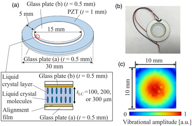
Fig. 1. (Color online) (a) Configuration and (b) photograph of the ultrasound LC lens. (c) Vibrational amplitude distribution of lens 1 at 22.7 kHz.
Download figure:
Standard image High-resolution imageWhen a continuous sinusoidal electric signal was input to the ultrasound PZT ring, a vibration mode in the radial direction was generated by the transverse piezoelectric effect, generating a concentric flexural standing-wave vibration on the two glass plates in the thickness direction. The acoustic wave propagating in the glass plates and the LC layer induces a difference in acoustic energy density among the LC layer, glass plates, and surrounding media (air) because most of the acoustic wave is reflected at the glass/air boundary owing to a large difference in acoustic impedance. The acoustic radiation force 21) is generated from the glass and LC and transferred to the air, causing a change in the molecular orientation of the LC layer. Because LC molecules have uniaxial optical anisotropy, the distribution of the refractive index in the radial direction of the lens is changed, and the incident light to the lens is refracted at the LC layer. Consequently, the lens acts as a variable-focus lens.
Figure 2(a) shows an observation system based on the LC lens. Here, the three LC lenses and an optical microscope (VW-9000, Keyence, Japan) were used. The optical characteristics of the LC lenses were evaluated under the single-Nicol condition with a polarizer. The LC lens was arranged on the optical axis between an objective lens of the microscope and the polarizer, and the distance between the LC lens and objective lens was 1 mm. A test target (1951USAF) was observed via the microscope through the LC lens. The brightness of captured images was analyzed using the image-processing software ImageJ to determine the focal point of the LC lens.
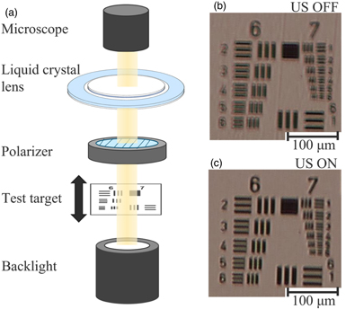
Fig. 2. (Color online) (a) Optical observation system using an LC lens and a microscope. Representative microscopic images obtained through an LC lens (lens 1) (b) without and (c) with ultrasound excitation at 22.7 kHz. The bars represent 100 μm.
Download figure:
Standard image High-resolution imageSeveral resonance frequencies were observed between 20 and 100 kHz for each LC lens. In this work, we focused on the axisymmetric second flexural vibration mode of the lens with two vibrational nodal circles; these resonance modes were generated at 22.7, 22.8, and 23.1 kHz on lenses 1, 2, and 3, respectively. Figure 1(c) shows the vibrational amplitude distribution generated on the surface of glass disc (b) in lens 1 at 22.7 kHz. A measurement area of 10 × 10 mm2 around the center of the lens was scanned by a laser Doppler vibrometer (NLV2500, PI Polytech, Waldbronn, Germany), and the vibrational amplitude was normalized by the maximum value. A concentric flexural vibration with two vibrational nodal circles was generated (only one nodal circle appeared in the measurement area), and the maximum vibrational displacement amplitude at the lens center was 9.0 μm for an input voltage of 37 Vpp. Figures 2(b) and 2(c) show representative microscopic photographs of the test target through lens 1 without [Figs. 2(b)] and with [Fig. 2(c)] ultrasound excitation. The blurred image [Fig. 2(b)] was changed to a focused image [Fig. 2(c)] without any changes in the LC lens position, indicating that the focal point varied along the optical axis as the LC lens was ultrasonically excited.
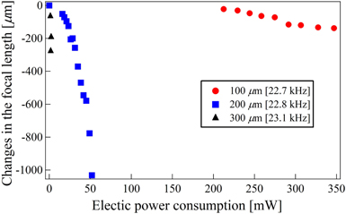
The focusing characteristics of the three LC lenses with different LC layer thicknesses were evaluated. Figure 3 shows the relationships between electric power consumption and change in the lens focal length. The focal length was determined from the sharpness of the captured image as the position of the test target changed; we defined the position with the maximum spatial gradient of image brightness as the focal point of the LC lens. The vertical axis indicates the distance of the altered focal length from the default focal position of each LC lens without ultrasound excitation (0 W) as the input voltage amplitude changed. It should be noted that the "focal length" is influenced by the optical characteristics of the objective lens of the microscope. A negative change in the focal length indicates that the focal point approaches the lens surface from the default position. For all LC lenses studied, the focal length decreased with increasing electric power consumption of the lens; hence, a larger input voltage induced a smaller radius of curvature, and the LC lens acted as a variable-focus convex lens under ultrasound excitation. The focal points of all lenses could be controlled by the input voltage. An electric power consumption threshold arose for each LC lens, which induced a change in the focal length, and the electric power consumption threshold increased as the LC layer thickness decreased. As the LC layer thickness changed, a higher electric power consumption was required for the lens with the thinnest LC layer to change the focal length; the electric power consumption at which lens 1 induced a focal length change of 70 μm was approximately 15 times larger than that for lens 2. Additionally, the gradient of the plots in Fig. 3 increases with the LC layer thickness of the lens. An electric consumption threshold at which turbidities were induced in the optical image was also observed, preventing the variable-focus function and resulting in the largest focal change for lens 2 (1.03 mm) among the three lenses. This result occurred because the LC layer became turbid and a "dynamic scattering mode," which also occurs in LC devices using electric fields, 22) was generated when the input voltage exceeded the threshold for each lens. This unstable phenomenon is attributed to turbulence in the LC layer induced by external forces (the acoustic radiation force) and the secondary restoring torque of the LC molecules, resulting in the light scattering in the LC layer and the fluctuation of the transmitted light. Dynamic scattering mode was observed in our ultrasound LC devices, and the detail was included in our previous study. 7)
Fig. 3. (Color online) Relationship between electric power consumption and changes in the focal length of LC lenses.
Download figure:
Standard image High-resolution image
Because a thinner LC layer requires a higher electric power consumption for the variable-focus function, the relationship between the acoustic radiation force acting on the LC layer and the anchoring force exerted by the orientational polyimide film is one of the most important factors to consider in designing an ultrasound LC lens. The anchoring force of the orientational film is inversely proportional to the square of the distance from the film to the LC molecules. 23) This trend implies that the lens with the thickest LC layer can be controlled by a smaller input voltage (and smaller acoustic radiation force) because the anchoring force on the LC molecules in the center region in the thickness direction decreases as the LC layer thickness increases. The experimental results in Fig. 3, where the gradient increases with the LC layer thickness, support this hypothesis. Although the lens with the thickest LC layer would give a larger change in the focal length and would be suitable for a variable-focus lens under the assumption that the distribution of the refractive index in the LC lenses is identical, the focusing characteristics of the LC lenses shown in Fig. 3 indicate that 200 μm is the optimal LC layer thickness. The molecular orientation in the LC layer under ultrasound excitation is determined by the balance between the acoustic radiation force and the restoring force originated from the elasticity of the nematic LC and the anchoring effect exerted by the orientational film. For lens 1, a larger anchoring force acted on the LC molecules owing to the thin LC layer, and a larger acoustic radiation force was required to change the molecular orientation, resulting in a small change in the focal length. In contrast, for lens 3, although the anchoring force of the orientational film was small and the LC molecular orientation in the central region in the thickness direction could be changed by a smaller acoustic radiation force, the stability of the molecular orientation was disturbed, and a dynamic scattering mode was induced by a smaller acoustic radiation force compared with lens 2.
The varifocal characteristics of ultrasound LC lenses were investigated in this work. Three LC lenses consisting of a PZT ring and a 100, 200, or 300 μm thick LC layer sandwiched by two glass discs were fabricated, and the focal lengths were measured under the single-Nicol condition via a microscope and a test target. A maximum focal length change of 1.03 mm was obtained for an LC layer thickness of 200 μm. An optimal LC layer thickness was observed for the variable-focus function, which was determined by the balance between the anchoring force of the orientational films and the acoustic radiation force generated by ultrasound vibration.
Acknowledgments
This work was partly supported by a KAKENHI Grant-in-aid (No. 19H020056) and Casio Science Promotion Foundation. We thank Kristi Hatch, Ph.D., from Edanz (https://jp.edanz.com/ac) for editing a draft of this manuscript.