
Abstract
This paper discusses the influence of displacement and patterning of phase shifters for piston mode operation of the temperature compensated surface acoustic wave (SAW) resonator on SiO2/LiNbO3 structure. As the phase shifters, Cu metals placed on the top surface of SiO2 are considered. First, the conventional Cu stripes are chosen, and their displacement is considered from interdigital transducer (IDT) aperture edges. It is shown that achievable transverse mode suppression is almost identical when the stripe shape is adjusted for each case. Next, Cu dots are considered as patterned phase shifters. It is shown comparable transverse mode suppression is possible also for this case. However, relatively strong SAW lateral leakage occurs when they are placed above IDT fingers. These results indicate that location and pattern can be added as design parameters for the phase shifters on SiO2. It is favorable for further enhancement of total device performances.
Export citation and abstract BibTeX RIS
1. Introduction
Now temperature compensated (TC) surface acoustic wave (SAW) devices are widely used in mobile communication handsets. Two TC mechanisms are often used; one is based on the bonding of piezoelectric LiNbO3 (LN) or LiTaO3 (LT) layer with lower thermal expansion coefficient such sapphire, 1–5) and another one is the use of SiO2 6) or SIOF 7) with a positive temperature coefficient of elasticity. 8–12)
In SAW devices, one of the most important design challenges is the suppression of transverse mode resonances. Various suppression techniques 13–28) have been proposed such as selective removal of SiO2, 17–22) bending resonator structure, 23) and piston mode design. 24–28) For the piston mode operation, phase shifters such as hammer head and metal dots are placed on electrodes near the aperture edges of interdigital transducer (IDT). When the SiO2 top surface is flattened, metals are not necessary to place directly on the electrodes but on the SiO2 top surface. 29) The metal stripes are placed above the aperture edges even in this case similar to the traditional piston mode design. Although they can be displaced and/or patterned theoretically, discussions have not been reported yet.
The authors discussed the influence of phase shifter location to piston mode operation of TC-SAW using SiO2/LN structure. 30)
This paper is an extension of this work and discusses the impact of displacement and patterning of the phase shifters from various aspects.
First, three phase shifters, shaped as stripes, and with different location are designed for the same resonator configuration, achievable performances are compared. The results indicate that mostly similar performances can be achievable after slight adjustment of phase shifter design.
Next, the discussion is extended to the application of metal patterning of the phase shifters. Here we deal with Cu dots with the same width of IDT fingers, and their impact is discussed. It is shown comparable transverse mode suppression is possible also for this case. However, relatively strong SAW lateral leakage occurs when they are placed above IDT fingers.
These results indicate that the metal location and shape can be used as new design parameters. This is desirable for further enhancement of total device performances.
2. Location impact of strip-like phase shifter
Figures 1(a) and 1(b) show the top and cross-sectional views, respectively, of the TC-SAW resonator structure used for the discussion. 131oYX-LN is used for the piezoelectric material, while Cu is chosen as the IDT material. SiO2 covers throughout the structure, and its top surface is assumed to be flattened. Table I shows structural parameters used in the simulation, and their symbols are defined in Fig. 1.
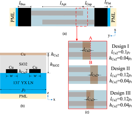
Fig. 1. (Color online) Device configuration used for the simulation. (a) top view, (b) cross-sectional view, and (c) location of metal stripes on SiO2.
Download figure:
Standard image High-resolution imageTable I. Employed structural parameters.
| Parameter | Value | Parameter | Value |
|---|---|---|---|
| hSiO2 | 570 nm(0.3pI) | pI | 1.9 μm |
| hCu1 | 95 nm(0.05pI) | w | 475 nm(0.25pI) |
| hLN | 10 μm | lFlat | 2 μm |
| lApt | 32 μm | lBus | 6 μm |
| lGap | 1.9 μm(pI) | hCu2 | 76 nm(0.04pI) |
Figure 1(c) shows the location of Cu stripes discussed here; Design I where the stripes are placed just inside on the aperture edges, Design Ⅱ where the stripes are just outside, and Design III which is a mixture of Designs I and II, and half of the stripes overlaps with the aperture.
The commercial software COMSOL® is applied for the three dimensional (3D) finite element method analysis, and no material loss is added for the simulation. In Fig. 1(a), the periodic boundary condition is applied to the upper and lower boundaries, while the perfect matching layer (PML) is applied to the left and right boundaries. On the other hand, in Fig. 1(b), PML is given to the bottom surface. All the material parameters are taken from the COMSOL® material library.
Figure 2 shows calculated admittance ∣Y∣ and conductance G per IDT period of the designed resonator without and with phase shifters. When the phase shifters are not given (Original), strong transverse mode resonances are clearly seen above the main resonance. On the other hand, all three piston mode designs offer good transverse mode suppression. Note that the results shown for Designs I–III are those giving the best transverse mode suppression, used stripe height hCu2 and length lCu2 for each case are given in Fig. 1(c). The optimal lCu2 increased slightly with a displacement of stripes to the outside.

Fig. 2. (Color online) Variation of calculated admittance ∣Y∣ (blue line) and conductance G (red line) per IDT period with the stripe location. Lines for Designs n are displaced vertically by 100 dB * n for clear visibility.
Download figure:
Standard image High-resolution imageAlthough Design III seems to offer the best transverse mode suppression judging from Fig. 2, a more detailed investigation is necessary. Anyway, we can conclude mostly similar performances can be achievable even when the stripe location is displaced after giving a slight adjustment of the phase shifter design.
3. Influence of patterning
In this section, patterning of the metal phase shifters is discussed. First, the use of dots instead of stripes is studied.
Figure 3 shows patterned phase shifters discussed in this paper. In Designs IV–VI, metal dots are placed on electrodes or their extension while they are placed on gaps or their extension in Designs Ⅶ–Ⅸ. Similar to the stripe cases, three locations are discussed: Designs IV and VII where the dots are placed just inside, Designs Ⅴ and VIII where the dots are just outside, and Designs VI and IX, still a mixture design of IV–V and VII–VIII respectively.
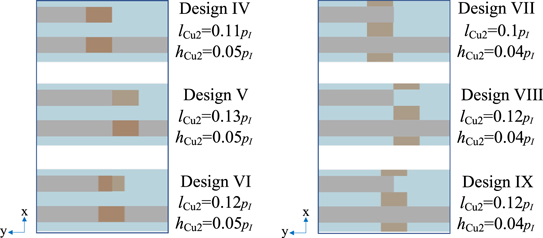
Fig. 3. (Color online) Patterned phase shifter with different location.
Download figure:
Standard image High-resolution imageIn the figure, dots height hCu2 and length lCu2 are given for each case. They are the settings giving the best transverse mode suppression given below.
Figure 4 shows calculated admittance ∣Y∣ and conductance G per IDT period of the Designs IV–VI. All three designs offer good transverse mode suppression comparable to the stripe cases shown in Fig. 2. However, G increases locally around 1.93 GHz for all three designs.
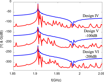
Fig. 4. (Color online) Calculated admittance ∣Y∣ and conductance G per IDT period of the Designs IV–VI. Lines for Designs V and VI are displaced vertically by 100 and 200 dB, respectively, for clear visibility.
Download figure:
Standard image High-resolution imageFigure 5 shows the displacement of the device with Design VI at 1.933 GHz. SAW amplitude is large near the dots and leakage to the bubar region is clearly visible. Although the leakage is also visible in the other designs, its amplitude is much smaller than this case.

Fig. 5. (Color online) Total displacement of 3D periodic device at 1.933 GHz.
Download figure:
Standard image High-resolution imageRequired dot height hCu2 and/or length lCu2 for the Designs IV–VI are a little larger than those for Designs I–III, respectively. This may be explained by the difference in the metallization ratio of the phase shifters.
Figure 6 shows calculated admittance ∣Y∣ and conductance G per IDT period of the Designs VII–IX. All three designs offer good transverse mode suppression comparable to the stripe cases shown in Fig. 2, and local increase in G is not visible for all three designs.

Fig. 6. (Color online) Calculated admittance ∣Y∣ and conductance G per IDT period for the Designs VII–IX. Lines for Designs VIII and IX are displaced vertically by 100 and 200 dB, respectively, for clear visibility.
Download figure:
Standard image High-resolution image
It is interesting to note that the required dot height hCu2 and length lCu2 for the Designs VII–IX are exactly the same as the Designs I–III, respectively.
4. Conclusions
This paper discussed the impact of displacement and patterning of the phase shifters for TC-SAW resonators on the SiO2/LN structure.
First, Cu stripes were chosen as phase shifters, and the influence of their location was compared for the same resonator configuration, achievable performances were compared. The results indicated that almost identical performances can be achievable when the stripe shape is adjusted for each case.
Next, the discussion was extended to the application of Cu dots as the patterned phase shifters. It was shown that comparable transverse mode suppression is possible also for this case. However, relatively strong SAW lateral leakage occurs when they are placed above IDT fingers.
These results indicated that the metal location and shape can be used as new design parameters. It is desirable for further enhancement of total device performances.
Acknowledgments
This work was supported in part by the Research Project under Grant A1098531023601318 and in part by the National Natural Science Foundation of China and the China Academy of Engineering Physics under Grant U1430102.