
Abstract
To confirm the feasibility of a theoretically proposed method of forming free-standing germanene [Araidai et al., J. Appl. Phys. 128, 125301 (2020).], we experimentally investigated the hydrogen desorption properties of hydrogen-terminated germanane (GeH) flakes. Thermal desorption spectroscopy analysis revealed that hydrogen desorption occurred during heating under an ultrahigh vacuum environment corresponding to a mass loss of 1.0 wt%. Moreover, we have found that using an ultrahigh vacuum, ambient and short-time annealing for hydrogen desorption is a key to sustain the crystal structures.
Export citation and abstract BibTeX RIS
1. Introduction
Germanene, the two-dimensional honeycomb structure of germanium (Ge), is an attractive material for next-generation group-IV nanoelectronics. It is theoretically predicted to possess a graphene-like Dirac-cone-shaped energy dispersion, 1) resulting theoretically in an extremely high carrier mobility (∼6 × 105 cm2V−1s−1). 2) In addition, there are a few differences between germanene and graphene. For example, germanene is composed of a buckled structure 3) with a heavy element, which offers a much more significant spin–orbit gap (23.9 meV) 4) than that of graphene (<0.05 meV) 5–7) and bandgap tuning by applying an external vertical electric field. 8,9)
To determine these exciting properties, germanene must be prepared artificially, as there is no free-standing germanene in nature. Up to now, many researchers have developed advanced growth methods such as vapor deposition 10–14) and surface-segregation methods, 15–18) enabling the synthesis of germanene on metallic substrates; specifically, Pt(111), 10) Au(111), 11,12) Al(111), 13,15) Cu(111), 14) Ag(111), 16–18) and graphene/Au/Ag/Ge on a silicon substrate. 19) It is however predicted that the Dirac-cone is destroyed, due to the strong covalent bonding with the element of the metallic surface. 20) Therefore, another approach to synthesize free-standing germanene is required in order to measure its electronic properties.
Against this background, we recently proposed a simple method to create free-standing germanene from hydrogen-terminated germanane (GeH). 21) According to theoretical calculations, hydrogen atoms could be removed from the GeH surfaces by heating and reducing the hydrogen partial pressure. Several reports of experiments in the thermogravimetric analysis on GeH exist that showed a weight change by thermal heating in an N2 22) or Ar 23) atmosphere. However, it is not clear whether or not there was hydrogen desorption. We recently demonstrated hydrogen desorption from GeH by using thermal desorption spectroscopy measurements. 21,24) However, the detailed crystal structures before and after heating have not been clarified. This study investigates gas desorption by thermal heating up to 300 °C from multilayer GeH flakes under different vacuum environments. We found that the crystal structures strongly depend on the base pressure and the annealing time; in-plane Ge-Ge bond structures in the flakes can be sustained after the hydrogen desorption.
2. Experimental procedure
A schematic illustration of the key steps to form multilayer germanene is shown in Fig. 1(a), where the atomic configurations were drawn by Visualization for Electronic and Structural Analysis. 25) We first synthesized multilayer GeH flakes using topochemical deintercalation of Ca atoms from CaGe2 crystals (CaGe2 + 2HCl → 2GeH + CaCl2), according to the synthesis technique proposed by Bianco et al. 22) A 3-g CaGe2 lump (Kojundo Chemical Lab.) [Fig. 1(b)] was soaked in a glass bottle with a 100 ml HCl solution at −40 °C for 5 days. Then the samples were washed with de-ionized water to remove residual CaCl2 and dried in a vacuum. The sample was in flake shape, about 1–3 mm in diameter [Fig. 1(c)]. Analysis by transmission powder X-ray diffraction (XRD) [Fig. 1(d)] and energy dispersion spectroscopy (EDS) [Fig. 1(e)] revealed that the crystal structure of CaGe2 was completely changed into GeH, although weak EDS signals of Ca and Cl still remain for the GeH sample. We guess that the weak signal is due to residual CaCl2.
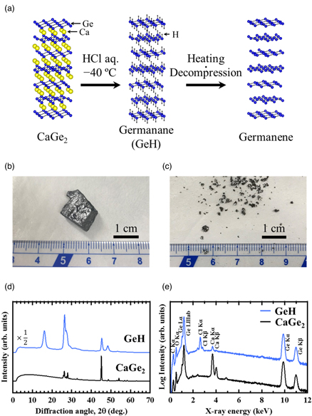
Fig. 1. (Color online) (a) Schematic illustration of the key steps to form multilayer germanene. Optical images of (b) the CaGe2 lump and (c) multilayer GeH flakes. (d) Transmission powder XRD patterns and (e) EDS spectra obtained from the CaGe2 lump (black) and multilayer GeH flakes (blue).
Download figure:
Standard image High-resolution imageWe next investigated the hydrogen desorption from the GeH flakes by thermal heating in various conditions (annealing time and base pressure). The details are summarized in Table Ӏ. In our previous study on thermal desorption spectroscopy (TDS), 21,24) it was revealed that the temperature at which hydrogen desorption is completed is around 300 °C, thus we chose the maximum temperature as 300 °C in the present study. The base pressure was varied from 10−6 to 10−3 Pa; the processing time from room temperature (RT) to 300 °C was varied from 35 to 300 min. After natural cooling to RT in a vacuum, the samples were exposed to air and characterized. The sample temperature evolution during the thermal heating is shown in Fig. S1 (see supplementary material for details, which is available online at stacks.iop.org/JJAP/61/SC1048/mmedia).
Table I. Summary of the heat treatment conditions for the GeH flakes.
| Sample name | Base pressure (Pa) | Max. pressure (Pa) | Temperature | Time (min) | Exhaust systems |
|---|---|---|---|---|---|
| UHV-35 | 10−6 | 10−4 | RT—300 °C | 35 | TMP/RP |
| UHV-300 | 10−6 | 10−4 | RT—300 °C | 300 | TMP/RP |
| HV-110 | 10−3 | 100 | RT—300 °C | 110 | TMP/diaphragm pump |
We used TDS (ESCO TDS1200II) to quantitatively analyze the gas desorption under an ultrahigh vacuum environment with a base pressure of less than 10−8 Pa. Here the samples were sandwiched between 0.1 mm thick carbon sheets and heated by infrared lamps with a heating rate of 20 °C min−1. A quadrupole mass spectrometer is installed in the target chamber, which allows in situ TDS analysis with the m/z range of 1–100. The structural properties of the flakes were characterized by transmission powder XRD (Rigaku R-AXIS VII) with Cu Kα radiation (λ = 1.5418 Å), scanning electron microscopy with EDS (JEOL JSM-7001FAEBSP), Fourier-transform infrared spectroscopy (FTIR; JASCO FT/IR-615V), and micro Raman spectroscopy (Nanophoton RAMAN-11) with a 532 nm laser. The samples for the FTIR measurements were prepared by the KBr pellet method.
3. Results and discussion
3.1. Hydrogen desorption from GeH by thermal heating
In this section, we will discuss hydrogen desorption from the GeH flakes by thermal heating. Figure 2(a) shows the ion current mapping for various m/z as a function of the temperature, where the color-scale intensity corresponds to the ion current. It is found that gases of m/z 1–2, 16–18, 28, 32, and 44 are detected above 50 °C. These gases of m/z 2, 18, 28, 32, and 44 correspond to H2, H2O, CO, O2, and CO2 respectively. We speculated that the gas of m/z 1 corresponds to the fragment ion derived from H2; those of m/z 16 and 17 correspond to fragment ions derived from the H2O. It is also found that gases of HCl isotope (m/z 36 and 38) and Cl2 isotope (m/z 70, 72, and 74) are detected above 260 °C, suggesting residual HCl. Next, we discuss the gas desorption quantitatively. Figure 2(b) shows the thermal desorption spectra of the six main gas species, i.e. H2 (m/z 2), H2O (m/z 18), CO (m/z 28), O2 (m/z 32), HCl (m/z 36), and CO2 (m/z 44). The gas desorption of CO, O2, HCl, and CO2 is insignificant compared with H2O and H2. At the low-temperature range (<150 °C), the H2O desorption is the largest; at the high-temperature range (>150 °C), the H2 desorption is the largest. The H2 desorption rate reaches a peak of 3 × 10⁻⁸ mol s−1 at 231 °C. The total desorbed H2 was estimated to be 5.0 × 10⁻⁶ mol, indicating that 75% of the H atoms desorbed from the GeH. 21) The corresponding mass loss of 1.0 wt% showed values almost the same as the previous works reported by Bianco et al. (≈1.1 wt%) 22) and Liu et al. (≈1 wt%). 23)

Fig. 2. (Color online) (a) Ion current mapping for various m/z obtained from the multilayer GeH flakes during thermal heating as a function of the temperature. (b) The thermal desorption spectra of the main gas species of H2 (m/z 2, blue), H2O (m/z 18, light blue), CO (m/z 28, green), O2 (m/z 32, pink), HCl (m/z 36, orange), and CO2 (m/z 44, purple). The heating rate was 20 °C min−1.
Download figure:
Standard image High-resolution imageTo reveal the loss of Ge-H bonding, we show the FTIR spectroscopy of the GeH flakes before and after the TDS measurements (Fig. 3). Before the TDS measurement (blue curve), Ge-H stretching vibration 22,26–28) at 1992 cm−1 and multiple Ge-H wagging modes 22,26–28) were observed at 557 cm−1 and 467 cm−1 respectively. Additionally, a sharp absorption at 856 cm−1 with a broad absorption was observed. We speculate that the sharp and broad absorption corresponds to the bending vibration mode of the Ge-H2 bond 22,29) and Ge oxide 26) respectively. A small absorption at 1620 cm−1 corresponds to the vibration mode Ca-Cl bond, 30) which is reasonable considering the EDS results [Fig. 1(e)]. After the TDS measurements (red curve), the absorption related to the stretching Ge-H vibration disappeared, and that of multiple Ge-H wagging modes was decreased, indicating that the hydrogen atoms were certainly fewer than before the TDS measurement. It is noted that absorptions related to Ge oxides exist for the flakes, though a clear Raman peak associated with an in-plane vibration mode in the Ge honeycomb lattice was observed, where the peak intensity does not change as a result of the hydrogen desorption. 24) It is suggested that the in-plane Ge-Ge bond structure is sustained after dehydrogenation. Several groups have previously reported thermal stability. Bianco et al. 22) claimed that GeH in a 5% H2/Ar atmosphere is stable up to 75 °C, though complete amorphization occurs above 175 °C; Liu et al. 23) claimed that GeH sealed in a vacuum quartz tube becomes germanene nanosheets at 270 °C and then Ge particles at 280 °C. On the other hand, we observe that the amorphization of GeH by heating to 300 °C under an ultrahigh vacuum does not occur. Therefore, it suggests that heating in a vacuum is necessary to remove the hydrogen while preserving the crystal structure of GeH.
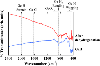
Fig. 3. (Color online) FTIR spectra obtained from multilayer GeH flakes before (blue) and after dehydrogenation (red).
Download figure:
Standard image High-resolution image3.2. Crystal structures of the flakes before and after thermal heating
Schematic illustrations of the experimental setup of the transmission powder XRD are shown in the insets of Fig. 4. We change the incident angle of the X-rays to be perpendicular (φ ≈ 90°) or parallel (φ ≈ 0°) to the surface of the flakes respectively. During the measurements (exposure time of the X-ray: 90 s for HV-110 or 120 s for the others), a sample was rotated in a range of 1° around a rotation axis. The diffracted XRD intensities were recorded using the imaging plate. First, we show diffraction patterns of the multilayer GeH flake (before thermal heating). The results are shown in Figs. 4(a) and 4(b), where simulated XRD patterns for 6R-GeH [Figs. 4(c) and 4(d)] and 2H-GeH [Figs. 4(e) and 4(f)] are also shown for comparison. For φ ≈ 90°, the pattern has 6-fold symmetry, and there are some overlapping diffraction spots (as indicated by red arrows). These features agree well with the simulation of 6R-GeH. For φ ≈ 0°, the pattern has a distinctive 2-fold symmetry (as indicated by the red arrows) corresponding to 6R-GeH 006 or 2H-GeH 002, meaning a layered structure. The interlayer distance was estimated to be about 5.55 Å, based on 2θ = 15.96°. The reported values of the interlayer distances are 5.506 Å (6R-GeH) and 5.82 Å (2H-GeH). 31) Hence, the structure of our GeH flakes corresponds to that of 6R-symmetry.
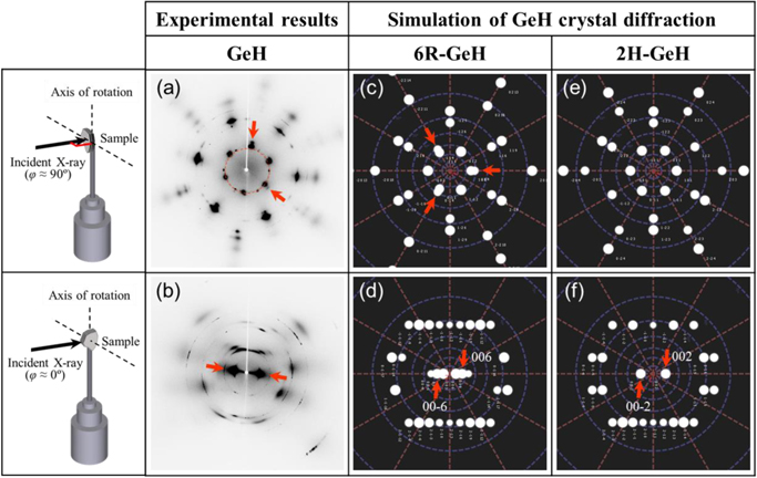
Fig. 4. (Color online) Transmission powder XRD patterns measured with (a) φ ≈ 90° and (b) φ ≈ 0° configurations for multilayer GeH flakes. The simulated patterns for (c), (d) 6R-GeH and (e), (d) 2H-GeH are also shown for comparison. The detailed measurement setups are schematically shown in the insets.
Download figure:
Standard image High-resolution imageNext, let us discuss the influence of thermal heating on crystal structures. Figure 5 shows the diffraction patterns obtained from the flakes after thermal heating under different conditions (base pressure and processing time). For UHV-35 and UHV-300, the patterns obtained by φ ≈ 90° configuration [Figs. 5(a) and 5(c)] have 6-fold symmetry, where strong (indicated by red arrows) and weak diffraction intensities were observed alternately. These features are similar to those found in the simulation result of 6R-GeH [Fig. 4(c)], suggesting that the in-plane crystal structure is sustained after heating under an ultrahigh vacuum condition. For HV-110, on the other hand, the pattern obtained by φ ≈ 90° configuration [Fig. 5(e)] has not only diffraction points but also Debye rings. Hence, it indicates that the in-plane crystal structures break from the initial GeH, then the Ge diamond structure is formed during heating. We speculate that some remaining gas species (e.g., O2 molecules) have attacked and destroyed the structure. The theoretical calculations based on density functional theory 32,33) reported that the O2 molecule attacking germanene easily makes Ge-O bonds, breaking the crystal structure of single-layered germanene. Consequently, we infer that thermal annealing in UHV conditions, an environment with less residual O2 molecules, is more desirable to create germanene. The patterns were also obtained by a φ ≈ 0° configuration; however, clear 2-fold symmetry, indicating a layered structure, has not been observed in any of the samples [Figs. 5(b), 5(d), and 5(f)]. We are considering that the difficulty of accurate parallel incidence of the X-ray and/or absence of the layered structures is the possible reason. A detailed study of microscopic observations, such as transmission electron microscopy, is needed to clarify this.

Fig. 5. (Color online) Transmission powder XRD patterns measured with φ ≈ 90° and φ ≈ 0° configurations for the samples of (a), (b) UHV-35, (c), (d) UHV-300, and (e), (f) HV-110. The detailed measurement setups are schematically shown in the insets.
Download figure:
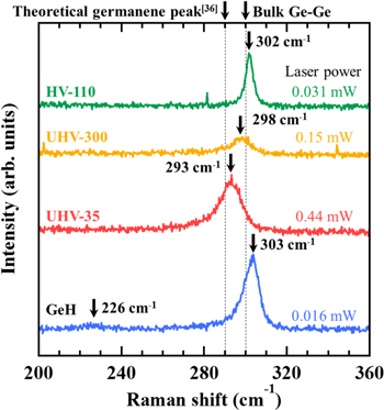
Standard image High-resolution imageFinally, we present the Raman spectra obtained from the flakes after hydrogen desorption. The results are shown in Fig. 6, where the GeH flakes (before hydrogen desorption) are also shown for comparison. Here, we carefully choose the laser power to prevent heating due to the laser, 34) because the layered crystal has a low thermal conductivity [GeH: 1.1 ± 0.3 Wm–1 K−1 (perpendicular direction)]. 35) For GeH, two peaks are observed at 226 and 303 cm−1, which correspond to out-of-plane and in-plane vibration modes in the Ge honeycomb lattice respectively. 22,27) For UHV-35 and UHV-300, the weak peak observed for GeH (at 226 cm−1) disappeared; the main peak was red-shifted compared to GeH. The red-shifted values interestingly, are larger for UHV-35. The main peak position for UHV-35 (at 293 cm−1) agrees well with the calculated results of free-standing germanene (around 290 cm−1). 36) For UHV-300, the main peak is blue-shifted compared to UHV-35, indicating that annealing time also affects the crystal structures (e.g., lattice strain). Here we note that the honeycomb lattice has remained even for UHV-300, as shown in Fig. 5(c). Hence, we infer that the shorter annealing time is better for sustaining the original honeycomb structures. For HV-110, on the other hand, the Raman peak was observed at 302 cm−1, which is very close to that for bulk Ge (300 cm−1). This is reasonable, taking into account the XRD results [Figs. 5(e) and 5(f)]. As a result, we can say that it is important to use short heating with an ultrahigh vacuum to sustain the crystal structures during hydrogen desorption. Additionally, we note that the XRD and Raman measurements were done in air, thus the flakes have some resistance to oxidation after hydrogen desorption.
Fig. 6. (Color online) Raman spectra obtained from the samples of UHV-35 (red), UHV-300 (orange), and HV-110 (green). The result of multilayer GeH flakes (blue) is also for shown comparison.
Download figure:
Standard image High-resolution image
4. Conclusions
We investigated hydrogen desorption from multilayer GeH flakes to verify the usefulness of a theoretically proposed method to create free-standing germanene. 21) We experimentally demonstrated that terminated hydrogen atoms in the GeH flakes could be removed as an H2 gas by thermal heating under vacuum conditions. Furthermore, XRD and Raman analysis revealed that the crystal structures strongly depend on the conditions during hydrogen desorption, specifically the base pressure and the annealing time. An ultrahigh vacuum and short annealing could provide the honeycomb Ge structures without H atoms (not bulk Ge). We believe that this is a good guidance for the creation of multilayered germanene in the near future.
Acknowledgments
This work was partly supported by JSPS KAKENHI (Grant Nos. 18K19020 and 19H04541) and the Foundation of Public Interest of Tatematsu. The authors thank Dr. Kenshi Kimoto of ESCO Ltd, Japan, for providing the opportunity to use the TDS measurement system and helpful discussions. The authors also acknowledge Mr. Tatsuo Hikage of the High Intensity X-ray Diffraction Laboratory, Nagoya University, Japan, for his cooperation in the XRD measurements.