
Abstract
Despite the high electrocatalytic activity of Pt and the fact it is a champion catalyst for the counter electrode (CE) of state-of-art dye-sensitized solar cells (DSSCs), its high cost, rarity, and the concern about its possible deterioration by the iodine-based redox electrolyte, has compelled the search for suitable and low-cost catalysts for CEs. To circumvent this issue, efforts were directed to exploring the suitability of various types of poly(3,4-ethylenedioxythiophene)(PEDOT)-based conducting polymers as the most suitable electrocatalysts for low-cost CEs. Amongst various types of PEDOT explored as CEs, micelle directed electropolymerized PEDOT:SDS (:sodium dodecyl sulfate) exhibited not only excellent catalytic activity (>Pt), as confirmed by cyclic voltammetry and electrical impedance spectroscopy investigations, but also fairly good photovoltaic performance exhibiting photoconversion efficiency of 5.8%, which is only slightly lower than the performance shown by Pt-based CE for the DSSCs fabricated under similar experimental conditions. Further improvement for the PEDOT:SDS-based CE surpassing the Pt-based CE is envisioned by morphological control and making their suitable composites with carbon-based nanomaterials.
Export citation and abstract BibTeX RIS
1. Introduction
Solar energy is one of the potential renewable energy resources that has the capability to solve all of our future energy needs. 1) Implementation of solar cells to use this immense energy is the most attractive way owing to the direct conversion of this energy into easily usable electrical energy. Although the harvesting of solar energy by silicon-based solar panel installations is ever-increasing worldwide, it is high cost compared to the cost/performance of electricity produced by fossil fuels. This can be understood by the fact that electricity generated by solar photovoltaics contributed to only 1.2% of the total worldwide energy consumption in 2015. 2) This has compelled the research and development of the next-generation, also known as third-generation, solar cells such as dye-sensitized solar cells (DSSCs), organic thin-film polymer solar cells, and perovskite solar cells, as a low-cost alternative to the commercial silicon-based solar cells currently being used. 3–5) Their low cost is attributed to them being lightweight and using low-cost raw materials, and their manufacture excludes the use of ultra-high purity raw materials, clean rooms, and high energy-consuming processes that utilize very high temperatures. Among the next generation of solar cells, DSSCs have attracted huge attention owing to their relatively lower cost of production, esthetic beauty due to utilization of various vibrant colors, transparency, and very good performance under low light intensities making them highly suitable for indoor light harvesting. 6) DSSCs are composed of a working electrode with a sensitizing dye absorbed to the most commonly used nano-crystalline titanium oxide (TiO2), a conducting counter electrode (CE) with a catalytic layer, and an electrolyte that fills the space between them.
In the past three decades, several efforts have been directed toward the optimization of various components of DSSCs, leading to the demonstration of photoconversion efficiency (PCE) surpassing amorphous silicon. 7,8) To compete with existing commercial silicon-based solar cells, the solution of the intriguing issues of DSSCs, like further enhancement in the PCE, reduction in the cost of production, and enhancement in the long-term ambient stability, is essential. The recent past has witnessed several efforts in this direction by the scientific community, such as the use of metal-free organic dyes, the removal of costly transparent conducting oxide (TCO), and low-cost Pt-free CEs. 9–11) Amongst the various components of DSSCs, CEs play a dominant role not only in completing the DSSC working cycle but also in reducing the cost by utilizing low-cost raw materials. In DSSCs, they display versatile functions like a catalyst supporting the regeneration of a redox electrolyte, as a positive electrode for collecting electrons from the external circuit, and reflecting the incident photons by a mirror-like electrode with thick Pt-sputtered on fluorine-doped TCO (FTO). 12) In principle, an optimal CE should not only have good electrical conductivity but should also possess high electrocatalytic activities for facile and efficient reduction of the redox couple. The catalyst material used for the fabrication of the CE must be coated on a conducting substrate to minimize the charge transfer overpotential. At the same time, a CE must also be able to address various issues arising from various interfaces, such as the series resistance (Rs) associated with the sheet resistance of the conducting glass/contact resistance of the cell and the charge transfer resistance at the CE/electrolyte interface. Electrochemical impedance spectroscopy (EIS) and Tafel polarization studies have been widely used to characterize the performance of novel CEs.
Although this mirror-like CE is advantageous for the back-reflection of light, in the case of transparent DSSCs or bifacial DSSCs needing transparent CEs, they are not suitable. Although carbon-based materials have been advocated as potential low-cost CEs owing to the high conductivity, good catalytic activities and high surface area, opaqueness poses the limitation for their use as transparent CEs. 13) Pt has been the most commonly used catalyst for the CE of DSSCs owing to its very high electrical conductivity as well as electrocatalytic activities demonstrating the highest PCE in the state-of-art high-efficiency DSSCs. The reactions at the CE rely on the type of redox couple in the electrolyte. In the case of the most commonly used iodine-based redox electrolyte consisting of the I−/I3 − redox couple, I3 − ions generated after receiving the electrons from I− ions regenerate the oxidized dyes and themselves get reduced at the CE. Although Pt catalysts have been demonstrated in high-performance DSSCs, the precious metal Pt is one of the most expensive components in DSSCs. Moreover, it was reported that the presence of a small amount of water in the electrolyte can lead to the deterioration of Pt. 14) Therefore, exploring a low-cost and high-performance alternative catalyst to Pt-based CEs has become a major focus for the realization of low-cost DSSCs.
Amongst the various possible alternative low-cost and Pt-free CEs, conductive polymers (CPs) are one of the potential candidate materials for DSSCs owing to their facile and versatile synthetic approaches, morphological control, tunable electrical/electrochemical properties, and favorable catalytic properties. 15,16) Amongst CPs, poly(3,4-ethylenedioxythiophene) (PEDOT) has been most extensively investigated as a CE, owing to its huge synthetic versatility, morphological control, and transparency, in combination with very good catalytic activities towards the facile reduction of the iodine-based redox electrolyte. 17) The recent past has witnessed the utilization of molecularly engineered sensitizing dyes and cobalt complex-based redox electrolytes, leading to a very high PCE of the DSSCs (>12%). 18,19) At the same time, PEDOT-based CEs have also been reported to impart nearly a similar PCE as compared to their Pt-based CE counterparts. 20,21) Although there are many reports on commercial as well as electrochemically prepared PEDOT as CEs of DSSCs, reported results were scattered pertaining to the limited selection of the type of the PEDOT undertaken either commercially or electrochemically, and the nature of the sensitizing dyes taken were also different. Although spin-coated PEDOT:PSS (:polystyrene sulfonate) has been widely used as the CE of DSSCs aiming towards low-cost CEs, in the majority of cases, commercial PEDOT:PSS has been directly spin-coated on the substrate to fabricate the CEs. Various commercial formulations of PEDOT:PSS have been available mainly for organic photovoltaic (OPV) and perovskite solar cells for surface modification and facile hole transport. In the case of DSSCs, catalytic activities and redox behavior play a dominant role, therefore, the best PEDOT formulation suitable for OPVs may not be optimal for CEs of DSSCs. Secondly, PEDOT:PSS has been used directly by spin coating leading to not only huge material loss but also lack any further modification to tune their surface and catalytic properties. On the other hand, electrochemically prepared PEDOT offers not only excellent material utilization but also fine-tuning of the surface properties of the thin films as well as electrocatalytic activities by the judicious selection of the electrical and electrolyte parameters during the electropolymerization. In this work, we have not only used a wide variety of PEDOT largely used for OPV and perovskite solar cells but also electrochemically prepared PEDOT:SDS as the CE using other conditions of DSSCs such as sensitizing dye, electrolyte, and photoanode fabrication with constant conditions. This is expected to figure out and propose the selection of optimum PEDOT in place of costly Pt for use as the potential CE of DSSCs. In this work, we would like to report about exploring the potential of various types of PEDOT as catalysts coated on FTO glass as CEs, aiming towards the proposal of suitable and low-cost CE for high-performance Pt-free DSSCs.
2. Experimental methods
2.1. Materials
4-tert-butylpyridine (tBP) was purchased from Sigma-Aldrich. Lithium iodide (LiI), Iodine (I2), Sodium Dodecyl Sulfate (SDS), were purchased from Wako, Japan. cis-bis(isothiocyanato)bis(2,2'-bipyridyl-4,4'-dicarboxylato) ruthenium (II) (N719) dye was purchased from Dyesol. TiO2 paste (Ti-nanoxide D/SP), 1,2-dimethyl-3-propylimidazolium iodide (DMPII), and 60 μm hot-melt sealing film (Meltonix 1170-60) were purchased from Solaronix. 3,4-Ethylenedioxythiophene (EDOT) was purchased from TCI. Solution processable PEDOT:PSS formulations like PH500, AI4083 and HTL Solar 3 were used as received.
2.2. Preparation of CEs
Pre-drilled FTO glass substrates were cleaned under sonication using ethanol, acetone and 2-propanol for 10 min each followed by UV/O3 treatment for 10 min. After cleaning, a mirror-like Pt was sputtered with a sheet resistance of less than 10 Ω/sq and used as a Pt-based CE for reference and comparison of variously prepared PEDOT-based CEs utilized for the present investigation. AI4083, PH500 and HTL Solar 3 were spin-coated on FTO at 2000 rpm for 60 s and annealed at 120 ℃ for 60 min to remove the residual solvents. Sodium dodecyl sulfate (SDS) doped PEDOT (PEDOT:SDS) thin films on FTO were prepared by galvanostatic electropolymerization as per the report by Ellis et al. 22) The solution for electro-polymerization consisted of the micellar aqueous solution of 0.1 M SDS and 0.01 M EDOT. Electro-polymerization of EDOT was performed with a potentiostat/galvanostat (HA-151, Hokuto-Denko, Japan). A two-electrode cell with a 2.0 cm × 2.5 cm predrilled FTO glass was used to deposit the PEDOT:SDS at a constant current of 0.65 mA for 3 min followed by their annealing at 120 ℃ for 60 min to complete this CE.
2.3. Device fabrication
The FTO glass substrate (15 Ω/sq) was cleaned ultrasonically followed by the UV/O3 treatment for 30 min as discussed above. Scree-printable TiO2 paste (Ti-nanoxide D/SP) was screen-printed and sintered at 500 ℃ for 45 min in a muffle furnace (FO100, Yamato Co., Ltd.), resulting in 15 μm thick TiO2. The TiO2 coated glass substrates were then dipped in 0.3 mM dye solution of N719 in ethanol for 24 h followed by rinsing with the same solvent ethanol to remove the un-adsorbed dye molecules. The photoanode was thus prepared and the different types of CEs were then sandwiched with Meltonix 1170-60 hot-melt spacer followed by injection of the iodine-based redox electrolyte through the pre-drilled hole. The composition of the electrolyte was 0.05 M I2, 0.1 M LiI, 0.5 M tBP and 0.6 M DMPII in acetonitrile. After injection, the two holes were sealed with the UV curable resin (Three-bond, Japan). A schematic representation of the cross-sectional view of DSSCs fabricated has been shown in Fig. 1.
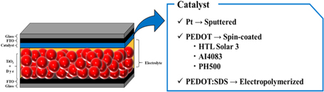
Fig. 1. (Color online) Schematic cross-sectional view of the DSSC utilizing different types of catalysts utilized for the fabrication of counter electrodes.
Download figure:
Standard image High-resolution image2.4. Device characterization
Cyclic voltammetry (CV) (HSV-100, Hokuto Denko, Japan) was measured in a three-electrode glass cell. A working electrode (Pt/FTO, HTL Solar 3/FTO, AI4083/FTO, PH500/FTO and PEDOT:SDS/FTO), CE (Pt plate), and a non-aqueous reference electrode (Ag/Ag+) were dipped in electrolyte which consisted of 10 mM LiI, 1 mM I2, and 0.1 M LiClO4 in acetonitrile. CV was conducted in a potential range of −0.8 to 1.0 V with respect to the Ag/Ag+ reference electrode at the scan rate of 50 mV s−1. For the solar cell performance evaluation, photocurrent density–voltage (J–V) curves were measured using an AM1.5G solar simulator (PEC-L01, Peccell Japan) for the standard incident light source and a source-measure unit (Keithley 6400). The intensity of light was calibrated to 100 mW cm−2 with a standard silicon photodiode. The device area was precisely controlled using a black metal mask with an aperture area of 0.25 cm2 during the photovoltaic performance evaluation. EIS was also used for characterizing the CEs using a frequency response analyzer (Solartron Analytical, 1255B), connected to a potentiostat (Solartron Analytical, 1287). An AC perturbation of 10 mV was applied in the frequency range from 0.1 Hz to 103 kHz.
3. Results and discussion
3.1. Cyclic voltammetry
Electrochemistry plays a dominant role in the investigation of the various components of DSSCs, such as dyes, electrolytes and catalysts of the CEs. Amongst the various electrochemical techniques, CV has been most widely and extensively used for the characterization of the CEs of DSSCs. 23,24) The observed waveform for reversible redox couple is the result of the various processes like polarization, diffusion and the rate of the electron transfer. Especially, the difference between the oxidation peak (Epo) and reduction peak (Epr), ΔEp of a reversible redox reaction, is an important electrochemical parameter and gives valuable information about the rate of the redox reaction. At the same time, it is inversely proportional to the rate of the redox reaction suggesting that a smaller value of ΔEp represents higher electroactivity. 25) Reaction kinetics of the I−/I3 − redox couple was studied by CV for different CEs to investigate their relative electrocatalytic activity. Figure 2 exhibits the CV obtained for Pt, HTL Solar 3, AI4083, PH500 and PEDOT:SDS and Pt/FTO in the presence of the I−/I3 − redox electrolyte. Typically two pairs of redox peaks can be clearly seen for almost all of the CEs under investigation except in the case of AI4083 and PH500, exhibiting a single and unclear redox peak indicating their poor electrocatalytic activity. At the same time, the lack of any redox peak for FTO suggests that it has no electrocatalytic activity and works merely as a transparent conducting substrate.
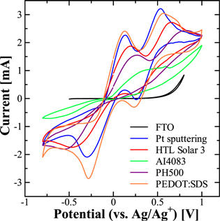
Fig. 2. (Color online) CV for different types of the CEs using I−/I3 − redox electrolyte measured at the san rate of 50 mV s−1.
Download figure:
Standard image High-resolution imageDifferent electrochemical parameters, such as oxidation peak current (Ipo), reduction peak current (Ipr), oxidation potential (Epo), and reduction peak potential (Epr), along with the ΔEp deduced from the CV shown in Fig. 2, are summarized in Table I. The two pairs of the redox peaks for the I−/I3 − redox couple are associated with two different types of involved redox reactions. 26,27) The first pair of redox peaks appearing at a relatively lower redox potential are associated with the two-electron redox reaction between the I3 − and I−, and the shape and position of the redox peaks were found to be highly affected by the nature of the CE under investigation. As discussed before, the electrocatalytic activity of the CE is negatively correlated with the ΔEp. CEs based on PEDOT:SDS not only exhibit the enhanced redox peak current but also, the ΔEp value of the PEDOT:SDS electrode (0.409 V) was found to be lower than that of the Pt electrode (0.430 V) indicating higher electrocatalytic activity for PEDOT:SDS than Pt towards the I−/I3 − redox reaction. On the other hand, the ΔEp value of the HTL Solar 3 electrode (0.667 V) was higher than the Pt electrode suggesting a relatively hampered catalytic activity for this CE as compared to that of Pt. On the other hand, for the AI4083 and PH500 CEs, two typical pairs of redox peaks were not clearly observed indicating their relatively inferior catalytic activities.
Table I. Electrochemical parameters deduced from CV, obtained with different CEs in the presence of I−/I3 − redox electrolyte.
| Pt sputtering | HTL Solar 3 | AI4083 | PH500 | PEDOT:SDS | |
|---|---|---|---|---|---|
| Ipo [mA] | 2.264 | 1.874 | — | 1.549 | 2.409 |
| Epo [V] | 0.135 | 0.191 | — | 0.270 | 0.130 |
| Ipr [mA] | −2.092 | −1.746 | — | −1.809 | −2.863 |
| Epr [V] | −0.295 | −0.476 | — | −0.555 | −0.279 |
| ΔEp [V] | 0.430 | 0.667 | — | 0.825 | 0.409 |
3.2. Electrochemical impedance spectroscopy
In combination with CV, EIS analysis has also been widely used to investigate the reduction of I3 − ions at CEs and characterize the electrocatalytic activities and a well-supported equivalent circuit is a powerful tool to study the performance of the DSSC CEs in operation. 28,29) Since the focus of this work was to explore the suitability of different PEDOTs as Pt-free low-cost CEs, other DSSC parameters were kept the same, such as the working electrode and redox electrolyte. EIS investigations were carried out using symmetrical devices consisting of two identical respective CEs and iodine-based redox electrolytes in the dark. Under EIS, analysis pertaining to the Nyquist plot and Bode plot was carried out to investigate the internal electron transfer kinetics at the electrolyte/CE interface. Figure 3 exhibits the Nyquist plots and the equivalent circuit for the electrochemical cells based on various CE materials in the presence of the I−/I3 − redox electrolyte in darkness. In the Nyquist plot, the starting point represents the magnitude of Rs whilst the 1st semicircle appearing in the high-frequency region is associated with the charge transfer resistance (RCT) existing at the interface of the CE and redox electrolyte. Electrical parameters such as Rs and RCT, deducted from the Nyquist plots after fitting the measured value in the equivalent circuit shown in Fig. 3, are summarized in Table II. To elucidate regions associated with Rs and RCT, the Bode plot, which is basically the frequency-dependent change in magnitude of the impedance or phase-shift under EIS, was also analyzed. Figure 4 exhibits the Bode plots for the same symmetrical cells based on various CEs in the presence of an I−/I3 − redox electrolyte in the dark. It can be seen from the Bode plot, there are two peaks, which are associated with two semicircles observed pertaining to the Rs and RCT, appearing in the low frequency (0.1–10 Hz) and high frequency (5000–15 000 Hz) regions, respectively.

Fig. 3. (Color online) Nyquist plots and the equivalent circuit for the electrochemical cells, using various counter electrodes in the presence of iodine-based redox electrolyte.
Download figure:
Standard image High-resolution imageTable II. Electrical parameters obtained from Nyquist plots and Bode plots for the symmetrical electrochemical cells based on various counter electrodes.
| Pt | HTL Solar 3 | AI4083 | PH500 | PEDOT:SDS | |
|---|---|---|---|---|---|
| Rs [Ω] | 23.70 | 23.48 | 21.36 | 28.90 | 19.63 |
| RCT [Ω] | 2.141 | 4.652 | 14.54 | — | 0.2302 |
| fp [Hz] | 1.19 × 10⁴ | 1.19 × 10⁴ | — | 18.9 | 6.91 × 10³ |
| τ [μs] | 13.4 | 13.4 | — | 8425 | 23.04 |
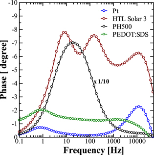
Fig. 4. (Color online) Bode plots for the symmetrical cells using various counter electrodes in the presence of iodine-based redox electrolyte.
Download figure:
Standard image High-resolution imageThis high frequency region peak associated with RCT can be used to investigate the relative kinetics of electron transport at the CE/electrolyte interface by estimating the interfacial electron lifetime using the relation τ = 1/2π fp, where fp is the peak frequency in the high-frequency region. Estimated values of the fp and τ from the Bode plot shown in Fig. 4 are summarized in Table II. It can be seen from this figure and table that catalysts like Pt and PEDOT:PSS formulation HTL Solar 3 exhibit similar electron lifetimes of 13.4 μs, while there was a slight increase in the observed lifetime (23.0 μs) for the PEDOT:SDS catalyst. Contrary to this, the commercial PEDOT:PSS formulation, PH500, exhibits very high electron lifetimes of 8.93 × 10³ μs. A lower value of τ corroborates the faster reaction kinetics of I3 − ions, resulting in improvement in the catalytic activity of the CE under investigation. It is also worth noting that for PH500 catalyst-based CE, the peak associated with the second semicircle in the Nyquist plot has been found to shift to the relatively much lower frequency region with a much-enhanced magnitude of the phase shift. This very long lifetime for PH500 could be attributed to its highly hampered electrocatalytic activity, responsible for the poor photovoltaic performance. In an interesting report on Pt-free metal and metal alloy based catalysts for DSSCs, Liu et al. have also reported that CEs utilizing catalysts with hampered electrocatalytic activities not only exhibit highly enhanced electron lifetime but also RCT peaks in the Bode plot highly shifted towards the lower frequency region and highly pronounced phase shift. 30) In the high-frequency region, Ohmic series resistance (Rs), which is mainly associated with the resistance of the FTO glass, can be determined from the onset of the first semicircle. It can be seen from Fig. 3 that the Rs for the cell prepared from the CE based on PEDOT:SDS was found to be the lowest (19.63 Ω). RCT and the double-layer capacitance of the electrode can be calculated from the first semicircle. The RCT observed for the CE utilizing PEDOT:SDS was even smaller (0.23 Ω) as compared to CE based on Pt/FTO (2.14 Ω), suggesting that PEDOT:SDS exhibits higher exchange current density than Pt. Therefore, the faster reduction rate of I3 − ions is expected due to the increased electrocatalytic activity of the PEDOT:SDS-based CE. On the other hand, very high values of Rs and RCT observed for the PEDOT:PSS-based CE formulations like AI4083 and PH500 may result in the hampered photovoltaic performances of their corresponding DSSCs.
3.3. Photovoltaic characterization
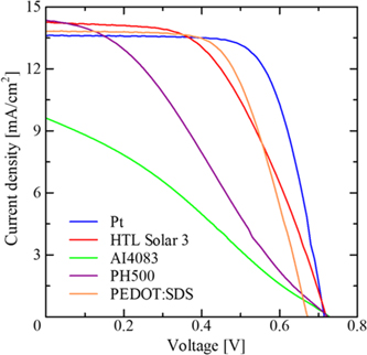
To explore the suitability of various CPs based on PEDOT as an electrocatalyst, DSSCs were fabricated after coating their thin films on FTO to use them as the CE of the DSSCs thus fabricated. It is worth mentioning here that other components of DSSCs such as N719 dye adsorbed photoanodes and the I3 −/I− redox electrolyte were kept the same to investigate the explicit performance of CEs under investigation. Photovoltaic characteristics for the DSSCs thus fabricated after 1 Sun simulated solar irradiation has been shown in Fig. 5. At the same time, photovoltaic parameters, such as the short-circuit photocurrent density (Jsc), open-circuit voltage (Voc), fill factor (FF), and PCE determined from the respective J–V curves are also summarized in Table III. A perusal of Fig. 5 and Table III clearly corroborates undoubtedly, the PCE for the CE based on Pt/FTO was highest at 6.46% efficiency, owing to the excellent catalytic activity of the Pt. On the other hand, CEs utilizing HTL Solar 3, based on PEDOT:PSS formulation prepared for perovskite solar cells by Ossila company and SDS doped PEDOT prepared under micelle-guided electro-polymerization (PEDOT:SDS), have also emerged as good electrocatalysts and function very well as CEs exhibiting a relatively better photovoltaic performance next to the Pt-FTO based CE. DSSCs utilizing HTL Solar 3-based CEs gave Jsc of 13.2 mA cm−2, Voc of 0.72 V, and FF of 0.52 corresponding to a PCE of the 4.95%. The same CE based on PEDOT:SDS exhibited a PCE of 5.77%, which is slightly lower than the DSSCs based on Pt-based CE. Although the higher electrocatalytic activity of this electrode as compared to Pt, confirmed by CV and EIS investigations, resulted in the improved Jsc, a slightly smaller Voc and FF compared Pt resulted in a slightly hampered PCE. This might be attributed to the relatively poor electrical conductivity of PEDOT:SDS compared to that of Pt. On the other hand, AI4083 and PH500 electrode cells exhibited highly hampered PCE compared to other CEs used for the present investigation. The DSSCs utilizing CEs based on AI4083 and PH500 exhibited the PCE of 1.86% and 3.11%, respectively, and the main cause of the decrease is the low FF, which is attributed to their poor catalytic activity and Rs, respectively, and is in accordance with the results of CV and EIS investigations discussed before. Therefore, enhancing the electrical conductivity of PEDOT:SDS by making their composites with carbon nanotubes or graphene appears to give the CE better performance, even surpassing Pt, and efforts in this direction are currently in progress.
Fig. 5. (Color online) Photovoltaic characteristics of DSSCs based on different types of counter electrodes after simulated solar irradiation of 100 mW cm−2.
Download figure:
Standard image High-resolution image
Table III. Photovoltaic parameters for DSSCs based on different types of counter electrodes. Values shown in the parentheses are standard deviations in parameters for DSSCs for four independent cells prepared under identical experimental conditions.
| Pt | HTL Solar 3 | AI4083 | PH500 | PEDOT:SDS | |
|---|---|---|---|---|---|
| Jsc [mA cm−2] | 13.3 (±0.686) | 13.2 (±0.729) | 8.98 (±0.542) | 13.8 (±0.827) | 13.9 (±0.157) |
| Voc [V] | 0.710 (±0.008) | 0.720 (±0.008) | 0.723 (±0.005) | 0.720 (±0.014) | 0.680 (±0.008) |
| FF | 0.686 (±0.008) | 0.519 (±0.024) | 0.286 (±0.004) | 0.312 (±0.004) | 0.612 (±0.004) |
| PCE [%] | 6.46 (±0.376) | 4.95 (±0.366) | 1.855 (±0.132) | 3.11 (±0.239) | 5.77 (±0.026) |
4. Conclusions
Pt-free CEs of DSSCs made using low-cost alternate materials based on the PEDOT class of CPs have been systematically investigated by CV, EIS, and photovoltaic characterizations. PEDOT-based CEs exhibited their capability as alternate low-cost components with slightly lower photovoltaic performance as compared to Pt. Especially, the CE based on PEDOT were fabricated either by spin coating or electro-polymerization, making them suitable for use as flexible and transparent CEs not made using special equipment like a sputtering unit or high temperature sintering, commonly used for the preparation of the Pt-based CE. CEs based on PEDOT:SDS exhibited fairly good a PCE of about 5.8%, which is slightly smaller as compared to the performance of Pt-based CE (6.5%) under the similar experimental condition of the DSSC fabrications, which was attributed to its high electrocatalytic properties as confirmed by CV and EIS. Further improvement in the performance of DSSCs utilizing PEDOT:SDS is expected by improving electrical conductivity and the morphology of the fabricated thin film leading to improved FF and efforts in this direction are currently in progress.
Acknowledgments
The authors would like to gratefully acknowledge the financial support under the Kyutech-UPM joint collaborative project.