

Abstract
A comparative experimental study of terahertz generation by optical rectification of femtosecond laser pulses with a wavelength of 1560 nm in a 100 μm thick slab of GaAs sandwiched between the walls of a tapered metallic waveguide and in a bulk GaAs crystal has been performed. In both cases, the velocity mismatch between the optical and terahertz beams propagating in GaAs was overcome by using the Cherenkov phase-matching method. The dependence of the terahertz time-domain signal amplitude, spectral bandwidth, and dynamic range on the focusing conditions were measured and compared. For both samples, the most efficient generation was observed for the 50 mm focal length lens. A significant improvement in the directionality of the terahertz emission from the thin GaAs slab due to the tapered waveguide was predicted by FDTD simulations and this was also confirmed experimentally.
Export citation and abstract BibTeX RIS
1. Introduction
The technique of terahertz time-domain spectroscopy (THz-TDS) was first introduced by Grischkowsky et al. in 1989 1,2) and in its contemporary widely used form, i.e. as a setup with photoconductive antennas (PCAs), Si lenses, and parabolic mirrors being reported in 1990. 3) Subsequently, the frequency range of the technique has been expanded and its sensitivity improved. 4) Nowadays, THz-TDS is one of the main methods of broadband far-infrared spectroscopy applicable for studying various physical properties of different materials from solids to gases. 5–8) In most typical THz-TDS setups, the LT-GaAs PCA that is triggered by an 800 nm wavelength femtosecond laser is used both as a terahertz emitter and detector. Unfortunately, highly stable, compact, and low-cost fiber lasers with a wavelength of 1560 nm have insufficient quantum energy for the above-band-gap excitation of LT-GaAs. Moreover, using two-step excitation via mid-gap states in LT-GaAs 9–12) as well as above-band-excitation of narrow-band-gap InGaAs, 13,14) have not been reported to yield sufficient terahertz radiation efficiencies.
Another way to generate and detect terahertz radiation is based on using nonlinear optical crystals, such as ZnTe and LiNbO3 (LN). ZnTe has a relatively large nonlinear optical coefficient, d14 = 68.5 pm V−1. 15) Additionally, it accommodates velocity matching between the 800 nm wavelength light and terahertz waves, 16) such that a long optical-terahertz interaction length can be achieved in ZnTe. For these reasons, ZnTe has been extensively used as a material of choice for nonlinear optical-terahertz generation and detection using a Ti:sapphire laser as the excitation source. Similarly, LN is one of the most promising nonlinear crystals due to its large nonlinear coefficient, d33 = 168 pm V−1. 15) To overcome a large optical-terahertz velocity mismatch in LN, the Cherenkov phase-matching scheme with a LN crystal attached to a Si-prism coupler has been proposed for both terahertz generation 17) and detection. 18,19) The most efficient generation has been achieved with a LN crystal operating as a slab 20–23) or ridge 24,25) waveguide for the pump optical radiation.
For nonlinear optical-terahertz generation and detection with the use of a fiber laser (1560 nm wavelength) as a light source, GaAs is a highly appropriate material. Aside from its large nonlinear optical coefficient, d14 = 65.6 pm V−1, 15) the noncollinear synchronism of the optical pulse (1560 nm wavelength) and terahertz waves (at 1 THz) can be achieved in GaAs at a rather small Cherenkov angle of ≈11° between the terahertz and optical beams. 26) As such, the noncollinear configuration can be implemented without using any coupling elements, i.e. the optical beam is made incident at an angle of ≈40° at the boundary of crystal surface and free space, with the terahertz beam propagating along the normal to the boundary. 26) Noncollinear electro-optic sampling of terahertz waves in GaAs has been demonstrated both with a bulk crystal 26,27) and with a thin crystal layer loaded into a tapered parallel plate waveguide (TPPWG). 28,29) A significant improvement in the detection efficiency had been achieved due to a concentration of the terahertz field in the TPPWG. 30) Noncollinear terahertz generation in a 600 μm thick layer of GaAs loaded into a TPPWG has also been demonstrated. 28)
In this paper, the effect of focusing conditions on the noncollinear terahertz generation efficiency and bandwidth is studied both for a thin (100 μm) layer of GaAs loaded into a TPPWG and for a bulk GaAs crystal. We also simulate numerically and verify experimentally, an improvement in the directionality of terahertz emission from the thin GaAs layer by means of the TPPWG.
2. Experimental scheme
The experimental setup is shown in Fig. 1. A mode-locked dual-wavelength (1560 and 780 nm), 100 MHz repetition rate femtosecond oscillator (C-FIBER-SP-3, Menlo Systems) was used as a light source. The laser beam at 1560 nm (90 fs pulse width, 45 mW average power) was used as a pump beam for terahertz generation, while the laser beam at 780 nm (120 fs pulse width, 10 mW average power) was used as a probe beam for terahertz detection. The pump beam was modulated at 2 kHz by a mechanical chopper, and focused by another lens onto the GaAs sample. To obtain different sizes of the focal spot, we used focusing lenses of different focal lengths f = 400, 200, 100, 50, 40, and 30 mm. Two samples were alternately used for terahertz generation. The first sample was a 100 μm thick and 5 × 10 mm2 in size slab of GaAs coated with gold on the wide faces and clamped between the walls of a TPPWG. The second one was a 10 mm long GaAs crystal with the laser incident surface of the crystal is 5 × 5 mm2 cross-section. The latter sample was used for reference. Terahertz radiation emitted from a sample was collected, collimated, and focused to a dipole-type PCA by a pair of parabolic mirrors (76.2 mm focal length, 50.8 mm diameter) for detection. The signal was measured by using a lock-in amplifier (SR830, Stanford Research Systems).
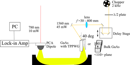
Fig. 1. (Color online) Schematic diagram of the experimental setup for terahertz emission from GaAs excited by a 1560 nm femtosecond laser.
Download figure:
Standard image High-resolution imageCrystallographic orientations of the GaAs samples and polarization directions of the pump and terahertz beams are shown in Fig. 2. The wide (5 × 10 mm2) face of the 100 μm thick slab of GaAs in TPPWG is the 〈100〉 plane [Fig. 2(a)]. The laser beam is incident on the  face of the slab. The plane of incidence is orthogonal to the [100] axis and the beam polarization is in the plane of incidence. In this configuration, the polarization of the generated terahertz wave is along the [100] axis, i.e. orthogonal to the waveguide walls, and the wave propagates as a fundamental TEM mode with no effect of the waveguide cutoff. In the case of bulk crystal [Fig. 2(b)], the laser beam is incident on the 〈110〉 face (5 × 5 mm2 size) of the crystal. The plane of incidence is orthogonal to the [001] axis and the beam polarization is in the plane of incidence. The polarization of the generated terahertz wave is along the [001] axis. It is important that the polarization of the terahertz waves emitted from both samples are in the same direction since the PCA detector is polarization sensitive.

Fig. 2. (Color online) Crystallographic orientation of the GaAs samples and polarization directions of the pump laser beam and generated terahertz wave.
Download figure:
Standard image High-resolution imageTo generate the terahertz wave propagating in the direction normal to the crystal entrance face, the pump laser beam is required to propagate at the corresponding Cherenkov angle. Taking into account GaAs dispersion in the terahertz frequency range, 26) Table I gives the values of this angle that provide Cherenkov phase-matching at the frequencies of 0.5, 1, and 4 THz for a laser beam of 1560 nm wavelength. The corresponding incidence angles of the laser beam on the crystal entrance face from free space are also shown. In the 0.5–1 THz region, the incidence angle is around 40°, and the laser beam can be introduced into the crystal without any coupling element. At 4 THz, however, the incidence angle becomes as large as 74°. This leads to a high reflection loss and, therefore, to the necessity of using a coupling prism. In our experiment, the incidence angle was set to 40° to provide Cherenkov phase-matching in the 0.5–1 THz frequency range.
Table I. Frequency dependence of the phase-matching angle and the incidence angle. 31)
| Frequency (THz) | Phase-matching angle (deg) | Incidence angle (deg) |
|---|---|---|
| 0.5 THz | 10.9 | 39.5 |
| 1 THz | 11.1 | 40.7 |
| 4 THz | 16.6 | 74.0 |
3. Experimental results
Figure 3 shows the experimental time-domain waveforms and corresponding frequency spectra (in log scale) of terahertz radiation emitted from the 100 μm thick GaAs slab in TPPWG for different focal lengths f of the focusing lens. The peak amplitudes of the waveforms show a sharp increase when the focal length decreases from 400 to 200 mm [Fig. 3(a)]. Correspondingly, both the frequency bandwidth and dynamic range also increase substantially [Fig. 3(b)]. A further decrease of the focal length below 200 mm adds little to the amplitude, bandwidth, and dynamic range. The reason why the signal jumps sharply at a transition from f = 400 to 200 mm is simple. The 1/e2 focal spot diameter  for a collimated Gaussian laser beam focused by a lens of a focal length f is given by the formula
32)
for a collimated Gaussian laser beam focused by a lens of a focal length f is given by the formula
32)

where  is the 1/e2 beam diameter on the lens and λ is the laser wavelength. By using Eq. (1), Table II shows the results of calculating the spot diameter
  for the laser beam diameter
  = 3 mm and each focal length f used in the experiment. For f = 400 mm, the spot size (Df
= 264 μm) substantially exceeds the width (100 μm) of the entrance face of the GaAs slab. Therefore, a significant part of the pump laser beam is scattered by the waveguide walls and lost for terahertz generation in the slab. For f = 200 mm, the spot size (Df
= 132 μm) becomes comparable to the entrance face width and the losses decrease substantially.
= 3 mm and each focal length f used in the experiment. For f = 400 mm, the spot size (Df
= 264 μm) substantially exceeds the width (100 μm) of the entrance face of the GaAs slab. Therefore, a significant part of the pump laser beam is scattered by the waveguide walls and lost for terahertz generation in the slab. For f = 200 mm, the spot size (Df
= 132 μm) becomes comparable to the entrance face width and the losses decrease substantially.

Fig. 3. (Color online) Experimental results for the 100 μm thick GaAs slab placed into the TPPWG. (a) Time-domain terahertz waveforms for different focal lengths of the focusing lens. (b) Corresponding power spectra.
Download figure:
Standard image High-resolution imageTable II. The focal spot diameter calculated using Eq. (1).
| Lens focal length f (mm) | Focal spot diameter Df (μm) |
|---|---|
| 400 | 264 |
| 200 | 132 |
| 100 | 66 |
| 50 | 33 |
| 40 | 26 |
| 30 | 19 |
For f < 50 mm, we observed a decrease in the signal. For a collinear parametric three-wave interaction of focused light beams, the optimal ratio of the crystal length L and the confocal parameter b is L/b = 2.84. 33) Due to a small angle of noncollinearity in our scheme (≈11°), this rule can be considered as a good approximation. For the length L = 10 mm of both our GaAs samples, it follows from the rule that the optimal focal length is f ≈ 48 mm, which is in good agreement with our experimental results.
Figure 4 shows the terahertz waveforms [Fig. 4(a)] and spectra [Fig. 4(b)] obtained from the measurements on the bulk GaAs sample. In this case, the peak terahertz amplitude gradually grows with reducing lens focal length down to 50 mm [Fig. 4(a)]. However, as in the measurements with the 100 μm thick GaAs layer, the signal starts to decrease for lens f values below 50 mm. Furthermore, the bandwidth of the generated radiation increases with decreasing laser beam width [Fig. 4(b)]. In the noncollinear scheme, the pancake-shaped pump pulse is tilted with respect to the generated terahertz wavefronts and its different parts generate a terahertz field having the same phase. The wider the laser beam, the thicker the region where the phase is constant and, therefore, the larger the wavelength of the generated terahertz wave. Reducing the width of the laser beam allows for decreasing the terahertz wavelength.

Fig. 4. (Color online) Experimental results for the bulk GaAs crystal. (a) Time-domain terahertz waveforms for different focal lengths of the focusing lens. (b) Corresponding power spectra.
Download figure:
Standard image High-resolution imageIn Fig. 5, the peak amplitudes from the two samples' terahertz emission are compared for different lens focal lengths and theoretical values of the conversion efficiency in amplitude-base reproduced from Ref. 33. In all the results, the efficiency is maximum at around L/b = 2.84. There are differences between the experimental and theoretical values for the decreasing tendency of the efficiency at long focal lengths. This may be explained by the improved THz beam emission pattern with larger focusing spot sizes with increasing focal length, suppressing the diffraction effect for THz waves. In other words, this suggests that some of the divergent THz radiation emitted under tightly focused conditions was not detected by the THz beam acquisition optics consisting of a Si hemispherical lens and a pair of parabolic mirrors. For f ≤ 200 mm, there is no significant difference in the terahertz amplitudes from the 100 μm thick slab and bulk crystal. The explanation for the drop in the amplitude from the 100 μm thick GaAs slab for f ≥ 200 mm is the same as above. In both samples, the signal intensity was largest for lens focal lengths of 50–100 mm.

Fig. 5. (Color online) Peak amplitude of the terahertz waves emitted from the bulk GaAs crystal and thin GaAs slab in TPPWG as a function of the focal length. The lower axis shows the focal length of the focusing lens and the upper axis shows L/b. The solid line shows the theoretical values of the conversion efficiency in amplitude-base reproduced from Ref. 33.
Download figure:
Standard image High-resolution imageIt should be emphasized that the comparable terahertz signals from the two samples were obtained despite significantly different radiation conditions in the samples. Indeed, in the bulk crystal, the laser pulse emits terahertz radiation in the form of a Cherenkov cone that diverges from the laser path. Since the crystal is thick, the cone grows large (∼4 mm in size) in the crystal. Additionally, due to a small Cherenkov angle (≈11°) the half-apex angle of the cone is large (≈79°) and, therefore, a significantly large fraction of the cone impinges the exit boundary of the crystal at a small angle. This section of the cone traverses into free space at a small angle with respect to the boundary normal and thus, does not experience significant diffraction divergence. In contrast, terahertz radiation generated in a thin (100 μm thick) slab of GaAs is expected to experience a strong diffraction divergence when emitted from the end face of the slab to free space. This can prevent efficient gathering of the radiation by collecting optics. In our setup, the undesirable diffraction divergence was suppressed by placing the GaAs slab into an expanding taper, i.e. TPPWG. To verify the positive effect of TPPWG on the directionality of the terahertz emission to free space, an FDTD simulation was performed.
4. FDTD simulation
Two-dimensional FDTD simulation was performed for two cases: (i) a 100 μm thick slab of GaAs sandwiched between two parallel metal walls [Fig. 6(a)] and (ii) the GaAs slab placed into TPPWG, which was used in the experiments, with rounded walls and an opening half-angle of 10° [Fig. 6(b)]. The calculated snapshots of the terahertz field are shown in Figs. 6(c) and 6(d). In Fig. 6(c), the terahertz radiation diverges concentrically from the end face of the GaAs slab. In Fig. 6(d), diffraction divergence is suppressed, and the emitted radiation is mainly within the radiation angle of 20°.

Fig. 6. (Color online) Results of FDTD simulation of the terahertz emission from a 100 μm thick GaAs slab sandwiched between two parallel metal walls and from the slab inserted into TPPWG. (a), (b) Simulation geometry of the two cases. (c), (d) Snapshots of the terahertz field emitted from the two structures. (e), (f) Angular distribution of the emitted terahertz power.
Download figure:
Standard image High-resolution image
To determine the angular distributions of the emitted terahertz energy more accurately, the terahertz intensity was calculated for points evenly spaced by a 10° interval on a semicircle of a 500 μm radius [green dots in Fig. 6(a)] and in the points evenly spaced by 1° in the range from 0° to 14° on an arc with the center at the intersection of the extension lines of the opening angle of the TPPWG [green curve in Fig. 6(b)]. The signal intensity at each measurement point was Fourier transformed to an intensity spectrum which was then integrated over the entire frequency interval to estimate the electromagnetic energy radiated at each angle. The results are shown in Figs. 6(e) and 6(f). In Fig. 6(e), the angular distribution is close to a Gaussian function. This explains the extensive divergence of the emitted terahertz radiation for the setup described in Fig. 6(a). From the focusing angle of the parabolic mirror, the radiation angle that can be coupled to the mirror is 36°. The red line in Fig. 6(e) shows the limiting angle that can be coupled to the parabolic mirror, and only 40% of the total radiation can be coupled to the mirror. This is in contrast with the TPPWG results shown in Fig. 6(f), wherein the high directionality of the terahertz radiation allowed for a 96% collection of the same parabolic mirror. The red line in Fig. 6(f) shows the radiation area within 20°, which is the taper angle. Thus, the TPPWG is confirmed to be a useful tool for improving the directionality of terahertz radiation sources.
5. Conclusion
The characteristics of terahertz radiation emitted from a GaAs crystal excited by a fiber laser having an emission wavelength of 1560 nm were measured for two types of samples, namely, a 100 μm thick GaAs slab inserted into a metallic TPPWG and a bulk (10 × 5 × 5 mm3) GaAs crystal. The dependence of the radiation intensity on the focal length of the laser-focusing lens was investigated for both samples. It was found to have a maximum at a focal length of 50 mm. Despite a strong diffraction divergence of the terahertz radiation emitted from the thin GaAs slab, the detected signal from the GaAs slab-in-TPPWG emitter was even stronger than that from the bulk crystal when the pump laser beam was optimally focused. The reason for this was explained by FDTD simulations, which demonstrated that the metallic taper significantly improves the directionality of terahertz emission. The experimental results show that the improved directionality results in a better coupling of the radiation to the pickup mirror. This study confirms that TPPWG can be used as a radiation element to improve the directionality of terahertz emission from nonlinear optical crystals.
Acknowledgments
This research was partially supported by the Collaborative Research Based on Industrial Demand from the Japan Science and Technology Agency, JST; project name: Development of Super Sensitive Electro-Optics Sampling Scheme for Terahertz Waves (Project No. 20100220). M.I.B. acknowledges support from the Ministry of Science and Higher Education of the Russian Federation (075-15-2020-927).