

Abstract
A continuous wave terahertz common path phase shifting interference (PSI) method using a liquid crystal (LC) phase shifter was developed in this work. Using an LC phase shifter is a good candidate for common path PSI, however, it is difficult to achieve pure phase measurement in the terahertz region owing to the strong dichroism of LC materials. In this study, hydrogen-bonded LC, which exhibits no dichroism at 2.5 THz, was introduced to an LC phase shifter and the common path PSI was demonstrated using an optically pumped gas laser at 2.5 THz. Our experimental and calculation results indicate that the phase difference between the ordinary and extraordinary rays of x-cut quartz substrates was successfully obtained by using the four-step phase shifting algorithm. Furthermore, the bias noise such as the influence of reflection at the sample surface was eliminated during data processing based on the four-step phase shifting algorithm.
Export citation and abstract BibTeX RIS
1. Introduction
A terahertz (THz) wave is an electromagnetic wave ranging from 0.1 to 30 THz and there has been considerable interest in spectroscopy, material science, and imaging. 1) Various materials such as plastics, wood, semiconductors, born, and papers are transparent for THz waves and these waves may detect unique chemical or biological agents. Therefore, applications involving THz imaging for non-destructive testing and non-invasive monitoring have attracted considerable interest. 2–13) THz imaging can provide applications that are unavailable in conventional visible imaging. A continuous wave (CW) THz source is a strong candidate for THz imaging due to its high power operation and higher signal-to-noise ratio 7–13) than a pulse THz source. However, in many cases, only the intensity images without phase information were achieved. The phase information is important for high-quality imaging and phase shifting interferometry (PSI) is a well-established method that utilizes optical frequencies. 14) Recently, CW-THz phase imaging using PSI based on the Michelson interferometer 7) and Mach–Zehnder interferometer 8) was reported. Nevertheless, these methods perform the intensity measurement by splitting two beams to determine the phase information. Using a common path interferometer is one good approach because the experimental set up is very simple and the system provides greater robustness against vibration. A liquid crystal (LC) device is a good candidate for common path PSI and several groups have reported results for the visible region. 15–17) In this method, electromagnetic waves of ordinary and extraordinary rays are interfered in one light pass. Furthermore, LC devices are generally very compact and can be driven by the usual interfacial circuit of personal computers.
On the other hand, the LC materials exhibit birefringence in the THz region 18–28) and are quite suited for tuning the phase of a THz signal by an external electric field. However, many LCs exhibit dichroism in this region, thereby leading to unwanted variation in the polarization state of the THz phase shifter. In this case, the phase and intensity change simultaneously by applying a voltage to the LC device, and use of the LC material in the common path PSI is difficult. The LC material with no dichroism is significant in common path PSI. In our previous work, we reported that the hydrogen-bonded LC exhibited no dichroism at 2.5 THz and demonstrated electrical phase tuning without intensity fluctuation. 29)
In this study, we fabricate an LC phase shifter using a hydrogen-bonded LC and we demonstrate the common path PSI in the THz region by using the shifter. We use an optically pumped gas laser as a CW-THz source and measure the phase difference between ordinary and extraordinary rays of x-cut quartz substrates using a four-step algorithm at 2.5 THz. Furthermore, we also calculate the transmittance of THz wave in the common path PSI by using the Jones matrix method.
2. Experimental methods
2.1. Phase shifting algorithm
Figure 1 shows the configuration of the common path PSI system using an LC phase shifter. In the case of crossed Nicols, the transmitted intensity of the THz wave I is given as follows;

Here, I' and I'' are the light intensity factors, which include noise signals, ϕs is the phase difference distribution between the extraordinary and ordinary rays of the test sample, and ϕLC is the phase shift introduced by the LC phase shifter. In this study, we adopt a four-step algorithm for data analysis. 30) The four output light intensity distribution data (i.e. I1 to I4) obtained corresponding to the phase shift values of ϕLC = π/2, π, 3π/2, and 2π, respectively, are given as follows;


Through the simple calculation using Eqs. (2)–(5), the light intensity factors I' and I'', which include noise signals, are successfully eliminated, leaving behind only the phase data, which can be extracted as follows;

If we know the sample thickness ds, the birefringence of sample Δns is given as follows:


Fig. 1. (Color online) Configuration of the common path PSI system using the LC phase shifter.
Download figure:
Standard image High-resolution imagewhere λ is the wavelength of the incident THz wave. Note that the LC phase shifter should control the phase without changing the intensity of the incident wave, i.e. an LC material exhibiting no dichroism is essential for this method.
2.2. Experimental set up
Figure 2(a) shows the structure of the electrically tunable LC phase shifter. An alignment of the molecules parallel to the substrate can be achieved by performing a suitable surface treatment or the coating of substrates. In this study, hydrogen-bonded LC material (PC29, LCC Inc., Japan) is injected into a sandwich cell where both inner surfaces are treated via parallel rubbing. This rubbing is conducted after coating of the planar alignment polyimide (SE2170: Nissan Chemical Industries, Japan) with the aim of obtaining a homogeneous alignment. The hydrogen-bonded LC shows a thermotropic LC phase due to the intermolecular hydrogen bonding between identical molecules [see Fig. 2(b)]. The THz properties of PC29 were reported in our previous work. 29) The cell thickness is determined by sheet spacers. Moreover, the direction of LC molecules can be controlled by an external electrical field. To maintain the high transmittance of the THz wave, we use z-cut quartz substrates and poly (3,4-ethylenedioxythiophene) polystyrene sulfonate (PEDOT/PSS) electrodes. PEDOT/PSS exhibits the high transmittance of the THz wave and acts as a good transparent electrode. 31–33)

Fig. 2. (Color online) (a) Structure of the LC phase shifter and (b) molecular structure of hydrogen-bonded LC.
Download figure:
Standard image High-resolution imageFigure 3 shows the optical configuration of our PSI process realized by using an LC phase shifter. An optically pumped gas laser was used as the CW-THz source. This laser can generate a CW-THz wave with sufficient power for precise measurements. A CO2 laser was used for pumping of the CH2F2 gas and a wavelength of 117.7 μm (2.5 THz) was used for our measurements. Here, the propagation direction of the THz wave is in the z direction as shown in Fig. 3 and the intensity of the transmitted THz wave was detected by the pyroelectric detector. The CW-THz wave of the optically pumped gas laser is Gaussian beam and the output beam diameter is about 15 mm. This beam diameter is small enough to investigate the common path PSI. Two wire grid polarizers were used for transmission measurements and the angle of the polarizer or optical axis is defined as the inset of Fig. 3. The LC device and sample were placed between polarizers of crossed Nicols (ΨP = 0° and ΨA = 90°). The angle between the polarizing direction of the THz wave and the optic axis of LC phase shifter was 45° (ΨLC = 45°). Moreover, the optic axis of a sample is perpendicular to the optic axis of the phase shifter (Ψs = −45°).

Fig. 3. (Color online) Experimental set up.
Download figure:
Standard image High-resolution image2.3. Simulation method
We calculate the transmittance of THz wave in the common path PSI by using the Jones matrix method. 34) The electric fields of the transmitted THz waves through the LC device and sample (Exout and Eyout, see Fig. 3) are described as follows:

where, P A , W s , and W LC represent the Jones matrix of the analyzer, sample, and LC phase shifter, respectively. Here P A is calculated from:

where ΨP and ΨA are the angle of the polarizers as defined in Fig. 3 and R (Ψ) is the rotation matrix,

The Jones matrix of the sample ( W s ) is expressed as follows:


where Ψs is the angle of the optic axis of the sample, Δns is the birefringence and ds is the thickness. Moreover, n''es and n''os are the imaginary parts of the complex refractive indices associated with the extraordinary direction and the ordinary direction of the sample, respectively.
Furthermore, the Jones matrix of the LC phase shifter ( W LC ) is given as

where ΨLC is the angle of the optic axis of the LC phase shifter. The Jones matrix of the z-cut quartz substrate in the LC phase shifter Q may be expressed as follows:

where dq and n''q are the thickness and imaginary part of the refractive index corresponding to the z-cut quartz substrate, respectively, and λ is the wavelength of the THz wave. Here, C and D are given as


where ΔnLC is the birefringence and dLC is the thickness. In addition, n''eLC and n''oLC are the imaginary parts of the complex refractive indices associated with the extraordinary direction and the ordinary direction of the LC layer, respectively. The transmitted intensity of the THz wave I is given as follows:

Here, we assume that the initial orientation condition and reorientation of the LC molecule by an external electric field in the LC phase shifter are as shown in Fig. 4. In this model, the directors of the LC molecules are uniformly distributed with an average angle of θ, which increases with increasing external electric field. The LC layer is very thick in the THz phase shifter, and hence this simple model can explain the THz phase shift properties of the LC phase shifter. In this case, the birefringence of the LC phase shifter ΔnLC is given as follows:


Fig. 4. (Color online) Simple model of the LC molecular orientation.
Download figure:
Standard image High-resolution imagewhere n'oLC and n'eLC are the real parts of the complex refractive indices associated with the extraordinary direction and the ordinary direction of the LC, respectively.
3. Results and discussion
3.1. Phase shift property of LC phase shifter at 2.5 THz
To investigate the phase property of the LC phase shifter, the transmittance is measured without the sample. Figure 5(a) shows the experimental transmittance of the LC phase shifter using PC29 as a function of the applied voltage at 2.5 THz. Here, the phase shifter is placed between the polarizers of crossed Nicols (ΨP = 0° and ΨA = 90°) as shown in Fig. 3. The angle between the polarizing direction of the THz wave and the optic axis of the phase shifter ΨLC is 45°. The vertical axes of Fig. 5(a) is normalized by data of THz intensity without sample and LC phase shifter.

Fig. 5. (Color online) (a) Experimental and (b) calculation transmitted THz intensity of the LC phase shifter at 2.5 THz.
Download figure:
Standard image High-resolution imageOn the other hand, the THz wave transmittance calculated using the Jones matrix method 34) is plotted as a function of the average LC molecular angle θ (see Fig. 4) as shown in Fig. 5(b). The transmittance is calculated from Eq. (18) and the transmitted THz intensity is 1 in the case without sample and LC phase shifter in the light path. Here, we set the angle of the polarizers and the optic axis of the LC phase shifter to ΨP = 0°, ΨA = 90°, and ΨLC = 45°. We consider the result without the sample, and hence we set Δns = 0 in the calculation. Furthermore, we set the thickness (dq) and imaginary part of the refractive index associated with the z-cut quartz substrate in the LC phase shifter (n''q) to 500 μm and 0.00047, respectively. 29) The relationship between the average LC molecular angle θ and the birefringence of the LC phase shifter ΔnLC is determined from Eq. (19). From our previous work, 29) the birefringence of PC29 is 0.17 at 2.5 THz. The absolute value of refractive indices associated with PC29 at 2.5 THz is currently being investigated and will be reported in the future. Therefore, in this study, we use the value of the ordinary refractive index in the visible region (n'oLC = 1.47 at 589 nm) as the ordinary refractive index of PC29 at 2.5 THz. The corresponding birefringence is 0.17, and hence the extraordinary refractive index of PC29 is set to n'eLC = 1.64 and the birefringence of the LC phase shifter ΔnLC is determined from Eq. (19). Here, when the ordinary refractive index n'oLC changes by 0.2, the birefringence of LC phase shifter ΔnLC changes by <2%. The value of ΔnLC changes only slightly with the value of n'oLC. Therefore, we believe that the calculation results shown in Fig. 5(b) are sufficiently valid for discussing the experimental result.
The variation in the transmittance determined via experiments [see Fig. 5(a)] is similar to that determined via calculations [see Fig. 5(b)]. Our experimental and calculation results indicate that applied voltage levels of 50–150 V correspond to director angles of 0°–70°. Furthermore, a non-zero transmittance at 150 V [see Fig. 5(a)] suggests that the LC molecules are only partly parallel to the applied electric field. This result indicates that our circulation method, which uses a simple LC orientation model (as shown in Fig. 4), is suitable for phase calculations of the THz LC phase shifter.
For four-step PSI, the phase shift values ϕLC = π/2, π, 3π/2, and 2π are required for determining the phase value of the sample [dashed lines in Fig. 5(b) denote the calculated results corresponding to the aforementioned shift values]. The ϕLC = π and 2π phase shift values correspond to the maximum transmittance and the minimum transmittance, respectively. On the other hand, the transmittance of half maxima corresponds to shift values of ϕLC = π/2 and 3π/2 as shown in Fig. 5(b). Using these calculation results, we determine the applied voltage required for four-step PSI [see the experimental results shown in Fig. 5(a)]. The lines in Fig. 5(a) indicate the points associated with phase shift values of ϕLC = π/2, π, 3π/2, and 2π, which correspond to applied voltages of V1 = 112 V, V2 = 99 V, V3 = 90 V, and V4 = 78 V, respectively. The operation speed of the LC phase shifter is important because the measurement time of the PSI depends on the operation speed of the LC phase shifter. In this study, the thickness of the LC layer in our LC phase shifter is 800 μm and we need few minutes to obtain the data of Fig. 5(a). This measurement time is not equal to the measurement time of the PSI because only four data are needed to obtain the phase of sample in the four-step PSI. However, the LC phase shifter is not fast in this stage. We think that the introduction of the electrospun nanofiber [35] is a good approach to improve the operation speed of the LC phase shifter.
3.2. Experimental and calculation results of the common path PSI at 2.5 THz
Figure 6 shows the experimental results of the common path PSI using hydrogen-bonded LC (PC29) phase shifter. In Fig. 6, the transmittance of a THz wave through the LC phase shifter and x-cut crystalline quartz is plotted as a function of the voltage applied to the LC phase shifter. In this study, two types of x-cut quartz substrates are measured. Here, we place the sample at the position shown in Fig. 3, and we set ΨP = 0°, ΨA = 90°, ΨLC = 45°, and Ψs = −45°. Figure 6(a) shows the result of sample 1, which is an x-cut quartz substrate made for a λ/4 wave plate at λ = 214.6 μm. The thickness (ds) of this sample 1 is 1141 μm in the catalog, and the corresponding birefringence is 0.047. Figure 6(b) shows the result of sample 2, which is made for a transparent quartz window. The thickness of sample 2 is 500 μm, but the birefringence is unknown. As shown in Figs. 6(a) and 6(b), the V–I curves with the sample data differ from those without the data [see Fig. 5(a)]. That is, the phase of the transmitted THz wave is affected by the birefringence of the samples.
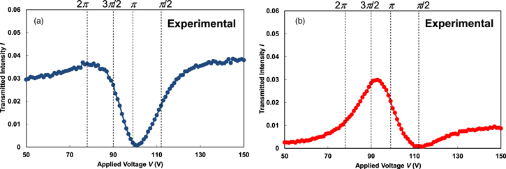
Fig. 6. (Color online) Experimental results of common path PSI performed on the x-cut crystalline quartz (a) sample 1 and (b) sample 2 at 2.5 THz.
Download figure:
Standard image High-resolution imageTable I shows the results of the common path PSI performed on sample 1 and 2. Here, we adopt the four-step algorithm for data analysis (see Sect. 2.2) and I1 to I4 correspond to the phase shift values for ϕLC = π/2, π, 3π/2, and 2π, respectively. These shift values are obtained by applying V1 = 112 V, V2 = 99 V, V3 = 90 V, and V4 = 78 V to the LC phase shifter (see Fig. 6). As shown in Table I, the phase difference distribution between extraordinary and ordinary rays of samples 1 and 2, ϕs1 = 0.25 and ϕs2 = −1.26 radian, is calculated from Eq. (6). The birefringence of the samples estimated from Eq. (7) is also shown in Table I. In the case of sample 1, phase unwrapping is needed to estimate the accurate value of the birefringence because of the large optical length of sample 1. Considering the experimental configuration (especially the optic axis of the LC phase shifter and sample), subtracting nπ (where n is an integer) from ϕs1 is reasonable for phase unwrapping. Here, the unwrapped phase of ϕ's1 = ϕs1 − π is used to estimate the value of the birefringence (see Table I). The estimated birefringence of sample 1 and 2 are −0.05 and the negative values are consistent with our experimental configuration. Furthermore, the estimated birefringence of sample 1 agrees with the catalog data of 0.047 and the estimated birefringence of sample 2 is consistent with the result of sample 1 and the reported value. 35,36)
Table I. Results of four-step phase interferometry performed on the x-cut quartz substrates.
| Parameter | Sample 1 | Sample 2 |
|---|---|---|
| I1 | 0.018 | 0.001 |
| I2 | 0.002 | 0.021 |
| I3 | 0.027 | 0.028 |
| I4 | 0.036 | 0.012 |
| ds (μm) | 1141 | 500 |
| ϕs (rad.) | 0.25 | −1.26 |
| ϕ's (rad.) | −2.89 | — |
| Δns | −0.05 | −0.05 |
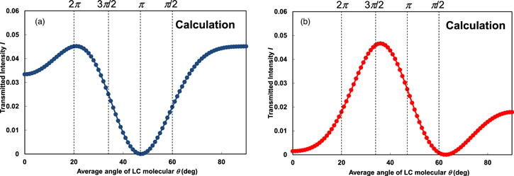
Then, we calculate the transmittance of THz wave in the common path PSI by using the Jones matrix method. 34) Here, the transmittance of the THz wave intensity through the LC phase shifter and the sample is calculated. Figure 7 shows the calculated THz intensity as a function of the average LC molecular angle θ. The intensity is calculated from Eq. (18) and in the calculation, we set ΨP = 0°, ΨA = 90°, ΨLC = 45°, and Ψs = −45°. In addition, we use the Δns and ds of sample 1 and sample 2 as shown in Table I. Here, we assume the imaginary part of reflective indices of samples n''os = n''es = 0.00047, which is the same value as that of the z-cut quartz substrates used in the LC phase shifter. Figures 7(a) and 7(b) show the calculation results of sample 1 and sample 2, respectively. The experimental THz intensity in Figs. 6(a) and 6(b) is, nevertheless, smaller than the calculated transmittance in Figs. 7(a) and 7(b). These results indicate that the bias noise was included in our experimental data. We think that this bias noise is most likely from reflection at the surface of the sample. However, this kind of attenuation is included in the signal of I'' [see Eq. (1)], which is eliminated during the calculation process as shown in Sect. 2.1. Therefore, the phase values of samples obtained from our experimental results are unaffected by reflection at the sample surface. These results indicate that the phase of samples is successfully obtained and using the hydrogen-bonded LC is effective in common path PSI associated with the THz region. For future applications such as detecting the unique chemical or biological agent, it is important to extend the measurement frequency of THz common path PSI. Since the LC materials with no dichroism are essential in the THz common path PSI using LC phase shifter, the broadband THz properties of hydrogen-bonded LC will be reported in our next paper.
Fig. 7. (Color online) Calculation results of common path PSI performed on the x-cut crystalline quartz (a) sample 1 and (b) sample 2 at 2.5 THz.
Download figure:
Standard image High-resolution image
4. Conclusions
In this study, we investigate a common path PSI in the THz region using a hydrogen-bonded LC phase shifter, which is based on a four-step phase shifting algorithm. First, a transmittance of 2.5 THz for the LC phase shifter is measured by using an optically pumped gas laser, and we successfully determine the applied voltage for common path PSI. Then we experimentally demonstrate the common path PSI using the gas laser. Since the hydrogen-bonded LC (PC29) exhibits no dichroism at 2.5 THz, we successfully obtain the phase difference between ordinary and extraordinary rays of x-cut quartz substrates by using the four-step phase shifting algorithm at 2.5 THz. We also estimate the birefringence of x-cut quartz substrates using the obtained phase difference data and the estimated birefringence values correspond closely to the catalog value. Furthermore, bias noise such as the influence of reflection at the sample surface was successfully eliminated during data processing based on the four-step phase shifting algorithm. We believe that using the hydrogen-bonded LC, which exhibits no dichroism at 2.5 THz, is effective in common path PSI employed in the THz region.
Acknowledgments
This work was supported by (i) Nippon Sheet Glass Foundation for Materials Science and Engineering, (ii) Suzuki Foundation and (iii) Adaptable and Seamless Technology transfer Program through Target-driven R&D (A-STEP, JPMJTM20B2) from Japan Science and Technology Agency (JST).