

Abstract
Acoustic metasurfaces have been attracting much attention due to their effectiveness in controlling sound wave propagation despite a structure well below the wavelength at operating frequency. We propose a novel decorated membrane resonator structure with multiple circular membranes leading to multiplexing the resonant modes through breaking symmetry of the membrane's vibrational modes. By numerical analysis, the structure is optimized for wideband (500 to 1500 Hz) sound absorption. The designed structure is fabricated by using a 3D printer and its sound absorption property is verified experimentally by an impedance tube measurement. The results demonstrate that the present approach is simple but effective to broadband sound absorption with thin and lightweight artificial acoustic structures.
Export citation and abstract BibTeX RIS
1. Introduction
Sound absorption/insulation has been one of the key technologies in developing next-generation architectures and automobiles. The conventional approach to the absorption has relied on sound absorbers such as glass wool and perforated panels with cavities behind them.1–3) These absorbers have thicknesses comparable to the wavelength of audible sounds requiring large mass which limits the range of application and their efficiency. In recent years, a new class of materials, called acoustic metasurfaces,4–8) have been attracting great attention. Metasurface in general is an artificial structure based on a build-in resonator that localizes strongly oscillating fields on the surface at certain frequencies and hence it can control/modulate the incident waves despite of its characteristic thickness well below the wavelength of the waves. As for acoustic applications, the metasurface has shown novel properties; acoustic cloaking,9–11) complete sound transmission12,13) /reflection14,15)/ absorption,16–20) and wave-front tailoring.21) In this study, we focus on the decorated membrane resonator (DMR),22) which is one of the acoustic metasurfaces that can achieve nearly 100% sound absorption at designated resonance frequencies. The DMR has, however, a sharp peak at the resonant frequency hampering the structure in practical applications in ambient sound environments with relatively wide frequency spectra. There have been several proposals attempting to overcome this issue such as some structures that combine DMR and a Helmholtz-resonator,23–25) and a structure that aims at superposing sound absorption peaks by arranging multiple DMRs with different diameters.26)
In the present study, we propose a new structure with a wideband by changing only the shape of the membrane in a single structure. Using three-dimensional finite-element analysis, we find an optimal structure for efficient absorption of sound with a frequency spectra within 500 to 1500 Hz,27) targeting to an in-vehicle noise reduction.
2. Decorated membrane resonator
Figure 1(a) shows the basic structure of DMR, which is similar to the structure proposed originally in Ref. 22. It consists of a cylindrical base with a cylindrical hole, a membrane at the opening, and a button at the center. Figure 1(c) shows the sound absorption coefficient of DMR. As shown in Fig. 1(b), the structure is 15 mm high, the sound absorbing frequency is about 1300 Hz, which corresponds to the wavelength of 260 mm. Thus the structure is sufficiently smaller than the wavelength. The high sound absorption occurs when the membrane and the backing air layer vibrate to convert sound energy into heat energy. The natural vibration modes of the membrane28) are coupled with the air layer behind to generate a new vibration mode which leads to an efficient sound absorption. When the DMR absorbs sound, the membrane is displaced concentrically as shown in Fig. 1(c). Even if the frequency is high, it becomes a concentric mode with increasing number of bellies. The DMR can achieve nearly 100% sound absorption at the resonance frequency with very narrow spectrum. In the original DMR proposed in Ref. 22, the button located in the center of the membrane was used to enhance the displacement of the mode at resonance leading to a piston effect for efficient energy dissipation. In the following sections, on the other hand, we show that high absorption can be achieved by structures without button.
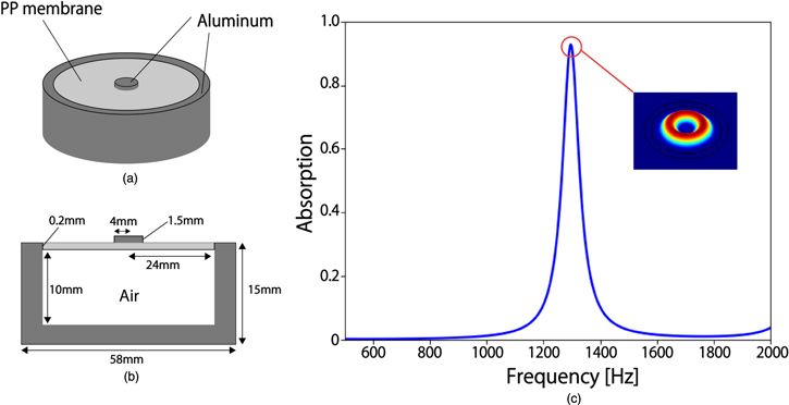
Fig. 1. (Color online) (a) A schematic of the DMR, (b) its cross-sectional view, and (c) the sound absorption coefficient at the size of (b). A sharp absorption peak appears at about 1300 Hz. The mode profile of the membrane at the peak frequency is shown in inset of (c).
Download figure:
Standard image High-resolution imageThe high efficiency for sound absorption of the DMR is achieved by the hybridization of vibration modes in the membrane and the backing air layer in the DMR.22) The (complex) acoustic impedance of the hybridized vibration mode can be expressed as  where
where  and
and  are the impedance of the membrane and that of the air layer in the DMR, respectively, and γ, p, s, ω represent respectively the adiabatic index of air, an average pressure of the incident wave, the thickness of the air layer, and an angular frequency of vibration. The highly efficient sound absorption occurs when the perfect matching conditions of the hybrid mode with an incident wave, expressed as
  and
and  are satisfied, where
  represents the impedance of air. The inverse of the membrane impedance
  can be expressed approximately as a summation of the Lorentzian for each individual mode of the membrane. In order to design properly the absorption spectrum, therefore, it is essential to control the number and position of the individual resonance mode of the membrane. The purpose of the present study is thus to increase the number of the membrane mode in a single DMR structure without losing the high absorption properties.
3. Multiple resonance membrane structure
3.1. Optimization of structure
The DMR originally proposed in Ref. 22 has a circular membrane and the excited modes are simple concentric leading to the sharp absorption at resonance frequencies. Here, we devise a structure that generates mode with non-concentric shapes. We examined the membrane-shape dependence on the sound absorption characteristics. Specifically, we investigated the multiplexing of resonance conditions with a structure that breaks the symmetry of the membrane's modes. Figure 2 depicts the structures to be studied.29) Figures 2(a) and 2(b) show, respectively, the "two membranes structure," in which two circles of the same radius are arranged with their center mutually shifted, and "three membranes structure" where three circles are similarly arranged, as preliminarily reported in Ref. 29. Note that the membranes are not overlapped within the dotted line and therefore the thickness is uniform everywhere in the membranes. Their cross-section view is shown in Fig. 2(c). Here both the membranes and the base structures were designed with polypropylene in order to reduce the total weight of the structure.

Fig. 2. (Color online) (a) Two membranes structure, (b) three membranes structure, and (c) their cross-section view.
Download figure:
Standard image High-resolution imageWe assume that the sound spectrum of the noise source can be represented by a simple Gaussian form with a peak at 1000 Hz and the standard deviation of 200 Hz, as shown in Fig. 3(a). This is the frequency band where the noise is highest in a typical passenger car.27) We then search for the optimum structure that absorbs the sound most efficiently. Specifically, the sound absorption coefficient was analyzed for various values (with an interval 1 mm) of the center distance. From the noise distribution s(f), depicted in Fig. 3(a), and the sound absorption coefficient a(f), depicted in Fig. 3(b), we can integrate it over a frequency range to obtain a sound absorption performance Q defined by the following formula.

This is an area of the graph in Fig. 3(c). The optimal structure can thus be obtained by finding the maximum Q within a range of the center distance.

Fig. 3. (Color online) (a) Simplified distribution of noise generated in passenger cars, (b) the sound absorption coefficient, and (c) the product of (a) and (b). The sound absorption performance is evaluated by calculating the area of the graph in (c).
Download figure:
Standard image High-resolution image3.2. Computational results
For the acoustic wave calculation, we used the software package COMSOL Multiphysics30) based on the finite element method (FEM). The triangular mesh divisions in the FEM simulations were performed for the surfaces of the sample and then swept to the entire sample with the same polygon. The mesh inside the membrane and the air layer beneath the membrane are divided into five layers. The finite element basis function used in the FEM simulations is the Lagrange P2 level. The Young's modulus, Poisson's ratio, density, and isotropic loss factor of polypropylene are set to be 1.47 × 10⁹ Pa, 0.4, 900 kg m−3, 0.06, respectively. Each circular part of the membrane has radius 20 mm and thickness 0.2 mm. Density and sound velocity of air are 1.2053 kg m−3 and 343 m s−1, respectively. In the present FEM simulation, the effect of the viscosity of air is neglected.
A plane wave of 1 Pa sound pressure was incident vertically from the top of the structure. In the analysis, the total system is assumed to be surrounded by a cylindrical hard wall with the same radius as the sample in order to emulate the absorption measurement performed in a cylindrical tube. Thus the sound absorption coefficient is obtained for an isolated DMR. The frequency spectrum was calculated for 500 to 1500 Hz with a 2 Hz increment. To evaluate the absorption characteristics, we calculated the absorption coefficient based on the transfer function method.31) The sound absorption coefficient is given by the following formula.
![${\rm{S}}{\rm{o}}{\rm{u}}{\rm{n}}{\rm{d}}\,{\rm{A}}{\rm{b}}{\rm{s}}{\rm{o}}{\rm{r}}{\rm{p}}{\rm{t}}{\rm{i}}{\rm{o}}{\rm{n}}=\displaystyle \frac{{\rm{s}}{\rm{o}}{\rm{u}}{\rm{n}}{\rm{d}}\,{\rm{p}}{\rm{o}}{\rm{w}}{\rm{e}}{\rm{r}}\,{\rm{n}}{\rm{o}}{\rm{t}}\,{\rm{r}}{\rm{e}}{\rm{f}}{\rm{l}}{\rm{e}}{\rm{c}}{\rm{t}}{\rm{e}}{\rm{d}}\,\left[W\right]}{{\rm{i}}{\rm{n}}{\rm{c}}{\rm{i}}{\rm{d}}{\rm{e}}{\rm{n}}{\rm{t}}\,{\rm{s}}{\rm{o}}{\rm{u}}{\rm{n}}{\rm{d}}\,{\rm{p}}{\rm{o}}{\rm{w}}{\rm{e}}{\rm{r}}\,\,\left[W\right]}$](https://content.cld.iop.org/journals/1347-4065/59/SK/SKKA06/revision2/jjapab7e3eieqn8.gif)
The reflected sound pressure was measured at two points placed between the sound source and the structure. The first point is located 50 mm away from the surface of the structure, whereas the second point is located 100 mm away from the surface of the structure. Figure 4(a) shows the sound absorption performance of the two membranes structure. From Fig. 4(a), one can see that the optimal center distance for the two membranes structure is 9 mm. Sound absorption performance is about 2.2 times higher than circular membrane (center distance is 0 mm). Figure 4(b) shows the sound absorption spectrum of the optimized two membranes structure.29) By breaking the symmetry, we successfully obtained wider absorption spectrum via splitting the single peak in the original DMR into three while maintaining a high value for all the peaks generated. The analysis shows that these peaks [A], [B], and [C] are all non-concentric modes. Figure 4(c) depicts the sound absorption performance of the three membranes structure. The optimal center distance for the three membranes structure is 34 mm from the figure. Again sound absorption performance is about 2.2 times higher than circular membrane (center distance is 0 mm). It has a high sound absorption coefficient in the bandwidth of 800 to 950 Hz, as shown in Fig. 4(d),29) and three sound absorption peaks are formed similarly to the case of the two membranes structure. The peaks [D] and [E] form a concentric displacement distribution mode as in the conventional DMR, while the peak [F] is a new mode in which each membrane resonates simultaneously. From the center distance, it was found that the two membrane structure is more suitable for practical use because of its more compact structure.
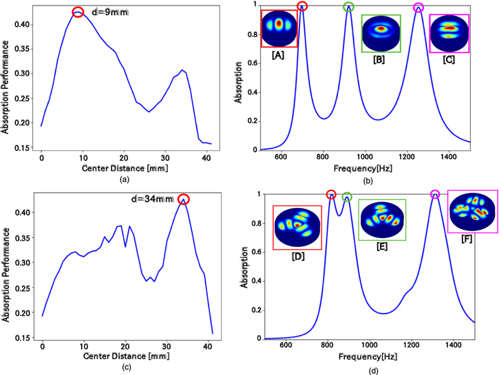
Fig. 4. (Color online) (a) Sound absorption performance, (b) sound absorption and mode diagram with two membranes structure. It shows that the structure is optimal when the distance between centers is 9 mm. (c) Sound absorption performance, (d) sound absorption and mode profile with three membranes structure. It shows that the structure is optimal when the distance between centers is 34 mm.
Download figure:
Standard image High-resolution image3.3. Experimental result
Based on the analysis described above, we fabricated an optimal structure using a 3D printer. We used Form2 manufactured by formlabs Inc. Both structures were made with 50 microns layers by 3D printer. Figures 5(a) and 5(c) are the photograph of a two membranes and a three membranes structures, respectively. We used a Clear resin as the material. The tensile modulus, flexural modulus, and notched IZOD for the resin are {1.6 GPa, 1.25 GPa, 16 J·m−1}, respectively. The radius of the two membranes structure and three membranes structure are 63 mm and 100 mm, respectively. The total height and the air layer of both of the structures are 25 mm and 15 mm. We used a commercially available polypropylene film for the membrane and affixed it to the edge of the base with an adhesive. In order to suppress the unfixing of the membrane attachment to the substrate, we created a lid with a 3D printer. We have also created shape of structure body of the lid as a polygon. This is to prevent the creation of gaps between base and the lid. The two membranes structure required about 3 h to fabricate the body, while the three membranes structure required about 5 h for it. We performed an experiment with an acoustic tube (Bruel & Kiar) at Industrial Technology Center of Okayama Prefecture. The acoustic tube uses the transfer function method to measure the reflectance of incident sound, same as our FEM analysis. The diameter of the structure was designed to be the same as the diameter of the acoustic tube. In the transfer function method, the transmitted wave was assumed to be zero. Measurement was performed at frequencies from100 to 3200 Hz for the two membranes structure and from 50 to 1600 Hz for the three membranes structure. Figure 5(b) depicts the measured results with the optimal two membranes structure. Three peaks emerged similarly as in the analysis. The maximum peak position error is about 6%. Figure 5(d) shows the measured results for the optimal three membranes structure. The peaks appeared at almost the same frequency as in the two membranes structure, except that only one peak was observed around 800 to 950 Hz. This is because similar modes of [D] and [E] in Fig. 4(d) might be mixed in the experiment. The maximum peak position error is about 0.3%. The peak near 1300 Hz is lower in the experiment than in the analysis. This is because the membrane might have been bent and the complex mode shown in Fig. 4(d) [F] could have not been reproduced.

Fig. 5. (Color online) (a) Fabricated structure, (b) experimental results for a two membranes structure. (c) Fabricated structure, (d) experimental results for a three membranes structure.
Download figure:
Standard image High-resolution image
4. Conclusion
We proposed a novel DMR structure with multiple circular membranes. We optimized the structure for high sound absorption performance and verified the possibility of wideband sound absorption by numerical analysis. Two structures we designed showed two times higher sound absorption performance than the conventional DMR. As a result, we succeeded in designing a high sound absorption effect for a wideband noise source between 500 to 1500 Hz. This has been realized by multiplexing the resonant modes through breaking the symmetry of membrane's vibration modes, while keeping a high sound absorption coefficient at each mode. It was evaluated by fabricating the structure using a 3D printer and by conducting experimental measurements. Our approach has great potential for the advancement of sound absorption/insulation technology which require broadband sound response in thin and lightweight artificial acoustic structures. It is also possible to break the symmetry of vibration mode in other ways, such as by changing the position and shape of the button. The examination of such approaches aiming for further broadband sound absorption is in progress.
Acknowledgments
This work was supported in part by the JSPS KAKENHI Grant No. 17K19035.