


Abstract
We use experiments and numerical simulations to study the rapid buckling of thin-walled cones as they impact a solid surface at high velocities. The buildup of air pressure inside the cone localizes the deformations to the impacting interface with the solid surface, leading to the hierarchical formation of an ordered pattern of small rhomboidal cells. In contrast, when the inner air pressure is not allowed to develop, the ordered pattern is destabilized and the cone collapses in a highly disordered state on long length scales. Numerical simulations confirm that the transition between ordered and disordered crumpling is governed by the competition between the elastic deformation energy of the shells and the work required to pressurize the air. Our results show how dynamic stabilization via tensioning suppresses long wavelength subcritical instabilities in shells and leads to the localization and propagation of short wavelength patterns.
Export citation and abstract BibTeX RIS
Buckling patterns in thin plates and shells arise due to the relative ease of bending a thin sheet compared to stretching it, and take a variety of forms, from global wrinkling to local folding and crumpling [1–3]. A particularly dramatic version of these patterns is seen in the buckling of axially loaded thin-walled cylinders; the reader can attest to this by standing on an empty aluminum can that will suddenly collapse into a crumpled, flattened disordered shape wherein the cylinder deforms on the largest scale possible, folding on itself [4]. This observation is in sharp contrast to theoretical studies which show that the energetically preferred patterns are a periodic array of buckled rhombi cells of typical size  (where r is the cylinder radius and t its thickness) composed of triangular planar surfaces known as the Yoshimura diamonds [5,6]. Indeed, decades of careful experiments confirm the results of the casual experiment alluded to earlier, i.e., producing ordered structures by compression of a cylinder is almost impossible. This is because the buckling instability of shells is well known to be subcritical, and thus very sensitive to imperfections [4,7,8]. Small imperfections associated with geometric defects thus grow rapidly on loading, and the entire structure collapses on large length scales with little reproducibility. However, it is possible to obtain the ordered Yoshimura patterns in experiments, a fact known to and exploited by artists and architects [9]. This requires one to prevent the growth of defects on large length scales, and can be done by introducing a slightly smaller rigid inner cylindrical mandrel inside the cylindrical shell before it is compressed [10] —this prevents the large wavelength buckling patterns from growing, so that the diamond-like ordered patterns arise naturally; the reader may have observed these patterns in tight-fitting trousers (or long soft boots) at the back of the leg, especially in the popliteal region. Given these observations that long wavelength subcritical instabilities are easy to excite in slowly loaded shells suggests that if a cylinder or cone is rapidly compressed to speed up the collapse, this would only amplify the disorder in the final crumpled state, in analogy with such systems as crystallization where slow annealing allows the material to solidify to an ordered, energetically favored configuration, while quick quenching drives the system into a disordered frustrated state.
Here we show that exactly the opposite is true —when a conical shell is smashed into a wall rapidly, it leads to the creation of an ordered 3D structure on small scales similar to inextensional fold patterns on cylinders and cones [4,11]. Our experiments use paper cones made by rolling flat paper sheets of thickness  and height
  into cones of varying opening angles, with an overlap of the sheets such that each cone is two paper-layers thick. The shape of the cone is maintained by a double-sided tape along one of its generators at the edge of the sheet. The cones are mounted on a heavy circular base with the tip facing down so that the air is sealed within the cone, and dropped along a vertical rail onto a flat glass surface at velocities of
  . A high-speed camera (Phantom V7.3) is used to image the cones from the side as they collapse upon impact with the surface at a frame rate of
  .
.
As the tip of the paper cone impacts the rigid surface, a dynamical cascade of folds is initiated as seen in fig. 1(a) and Supplementary Movie SupplementaryMovie1.mp4. The cone deforms at the impact zone into localized rhombic patterns even as new rhombic indentations nucleate typically between two indentations of the previous generation. Although the cone deforms most strongly along a narrow circumferential rim in the neighborhood of the contact zone, we see that the cone is also weakly indented away from this zone. When the cone is unfolded by cutting it open along a generator and flattening it, we see that the process leads to an ordered tiled pattern —see fig. 1(b), (c). The rhombi composing the pattern may be characterized in terms of their azimuthal and radial length,  and lR, respectively, as shown in the inset to fig. 1(c). lR initially increases with the radial coordinate R, but quickly saturates at a constant value as shown in fig. 2(a). In contrast,
  continues to increase well beyond the point at which lR saturates, leading to more elongated cells farther from the cone tip.
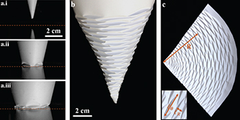
Fig. 1: (Color online) (a) Three snapshots of a paper cone with a 29° opening angle compressing against a glass surface. (b) The interface between the cone and the surface is indicated by a dashed red line. Unfolding the compressed cone reveals an ordered Yoshimura-like pattern. (c) The pattern can be examined by cutting the cone along one of its generators and flattening it onto a plane. The length scales of the pattern cells in the radial (lR) and azimuthal ( ) directions can then be measured as a function of the distance, R, from the tip of the cone (inset).
Download figure:
Standard image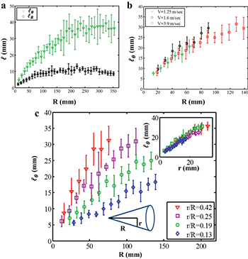
Fig. 2: (Color online) (a) The pattern length scales lR and  as a function of the radial coordinate R for a cone with opening angle of
  . (b) Varying the velocity at which the cones impact the surface has little effect on the pattern
  . (c) However, by changing the opening angle of the cone, the dependence of
  on R can be tuned. The
  curves can be collapsed onto one master curve when plotted as a function of r (inset).
Download figure:
Standard imageThe form of the patterns depends on a number of parameters such as the cone opening angle, paper thickness, and impact velocity, and so we systematically vary them. Although the ordered patterns only form under dynamic conditions, small variations in the velocity (by a factor of three) do not change the observed pattern, as seen in fig. 2(b). Changing the cone opening angle,  , where r is the local cone radius indicated in fig. 2(c) changes the form of the rhombi. For larger α,
  grows more rapidly with R, as shown for four different opening angles in fig. 2(c). This suggests a dependence of
  on r, as shown by the data collapse onto one master curve in the inset to fig. 2(c), indicating that the shape of the pattern is determined locally by the instantaneous value of r in contact with the surface. In contrast to the strong dependence of
  on the cone geometry, we do not measure any dependence of lR on α.
To characterize the role of sheet thickness on the pattern, we varied it from the typical value we used, 0.1 mm, to a range spanning 0.075–0.28 mm. We find that the effect of thickness on the length scales of the rhombi pattern was very small. This observation strengthens the claim that the geometry of the crushed pattern is governed by the dynamics during the crushing process, rather than by minimization of elastic energy. However, the paper thickness does affect the region of the cone where a Yoshimura-like pattern emerges. At the very tip of the cone, where the rhombi sizes are expected to be very small, the paper creases instead of buckling into a rhomboidal pattern over a distance that is strongly affected by thickness, from few millimeters for 0.075 mm thick paper to about 5 cm for 0.28 mm thick paper.
While small variations in the velocity of impact do not change the observed folded patterns, when the cone is compressed quasi-statically the patterns disappear and the cone crumples in a disorderly fashion with no localization (see Supplementary Movie SupplementaryMovie2.mp4). This difference suggests a role for dynamic effects associated with inertia in the shell and a potential role for air pressure in stabilizing the long wavelength modes excited by quasi-static compression. The relative role of inertial to elastic forces (per unit area) is determined by the ratio  [8]. Substituting parameter values (
 ,
,  ,
,  ,
,  with Young's modulus of paper
  and the typical length and time scales for buckling rhombi
  and
and  , respectively), we find that the ratio
  , i.e., inertial effects are negligible. This leaves only the air pressure as a pattern stabilizer, wherein it plays the role of a dynamic mandrel to suppress the growth of long wavelength defects in favor of the short wavelength ordered patterns that form at the zone of impact. To test this experimentally, we mount the cones on bases through which four circular holes of varying diameter, d, are cut, as shown schematically in fig. 3(c). This allows air to escape the cones and reduce the rate of buildup of the dynamic pressure so that the compact patterning associated with tip collapse becomes less ordered —fig. 3(a).

Fig. 3: (Color online) (a) Allowing air to escape the cone results in disordered buckling of the cone. (b) The rhombic indentations propagate a typical height, h, along the generator of the cone before folding on themselves. (c) The influence length h as a function of the axial location H for cones mounted on bases with different sized holes, decreasing the internal air pressure as the cone is compressed.
Download figure:
Standard imageTo quantify this change in pattern evolution as a function of the hole size (see Supplementary Movies SupplementaryMovie1.mp4 and SupplementaryMovie3.mp4), we measured the size of the indentation zone h shown in fig. 3(b) as a function of the axial distance H from the tip of the cone for different hole sizes, where h and H are extracted from real time imaging of the crushing process closely and correlate with  and R, respectively. For small holes, the air pressure inside the cone is high, and the new indentations remain localized near the interface of the cone and the surface. For larger holes, the air pressure inside the cone is small, and once indentations are created they grow rapidly toward the base of the cone. In addition to the increase in size the indentations reach, the release of air pressure also increases the chance for a dent to nucleate away from the surface, causing the cone to buckle catastrophically (see Supplementary Movie SupplementaryMovie4.mp4). In the absence of holes, the increase in the internal pressure
  scales as the ratio between the uncompressed volume of the cone and the truncated compressed cone, of half the volume, and yields
  . Direct measurement during compression confirms this buildup of pressure within the cone; we observe a peak pressure difference of between 16 and 27 kPa. When the holes are large enough so that as the air escapes viscous and compressible effects are negligible,
  , where
  and uair are the density and velocity of the escaping air, respectively. The velocity uair is estimated by equating the flux of air escaping the cone to the rate of the cone's volume change. For a cone impacting the surface at a velocity of 1 m/s, this calculation yields
  , three orders of magnitude lower than in the pressurized case, confirming that the dominant stabilizing effect that causes localized folding at the impact zone is due to pressurized air in the cone.
We validated the buildup of pressure by measuring the internal gauge pressure as the cone compacts with an ELVEFLOW MFP Inline Pressure Sensor FlowPlus embedded in the top circular plate sealing the cone. The cones were dropped from a height of 1.2 m and pressure data recorded at a rate of 500 Hz. The results are plotted in fig. 4; the interior of the cone attains a peak internal pressure of between 16 and 27 kPa. Leaks at the interface between the top plate and the cone's base, porosity of the paper, and leaks due to delamination of the cone along its lateral seam all contribute to the fall in pressure at the end of the experiments, and the discrepancy between the measured peak pressure and predicted theoretical peak pressure of 100 kPa.
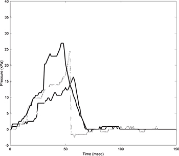
Fig. 4: Internal gauge pressure of a sealed cone compressed from a height of 1.2 m. The experiment was repeated four times on cones of identical thickness and dimension.
Download figure:
Standard imageTo understand our results quantitatively, we recall that an energy-based linear stability analysis predicts that the typical length scale of the buckling pattern would scale as  . However, the buckling patterns observed do not follow this scaling relation because the pattern evolves dynamically and cannot be described purely in terms of energetics. Therefore, we numerically simulated compression of conical shells using a thin-shell theory based on the Kirchhoff-Love assumptions that the shell geometry and mechanics can be characterized entirely in terms of the geometry of its midsurface. Furthermore, we consider only geometric nonlinearities, and limit ourselves to elastic buckling since this always precedes plastic deformations and determines the basic patterns.
The shell can be parameterized entirely by the geometry of a midsurface S; more specifically, let A be an annulus in the plane and  the coordinate function embedding S (illustrated schematically in fig. 5(a)). The thin shell of thickness t is then parameterized by

where  is the surface normal of S. For the large deformations of a thin conical shell, geometric nonlinearities dominate material nonlinearities, and so we use a simple linear St. Venant-Kirchhoff material model. Denoting by
  the embedding of the cone at rest, before compression, and letting
  be its corresponding embedding, the Steiner expansion formula [12] then gives the elastic energy in terms of geometric quantities on the midsurface: [13,14]

where  , and a, b, c are the first, second, and third fundamental forms of S that can be expressed in terms of r by
  ,
,  , and
, and  . Here
  is the rest surface area element, and is discretized using a piecewise-constant metric over S,
  is the rest metric of the midsurface (the first fundamental form
  of
of  ), and k1, k2 are Lamé parameters.
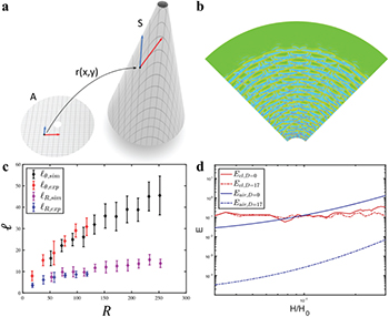
Fig. 5: (Color online) Schematic of simulation setup. The midsurface S of the cone in space is parameterized by an embedding function  on an annulus A in the plane (a). Simulation of a crumpled cone of opening angle 29°. The crease pattern in the virtual cone can be visualized with a heat map of mean curvature; curvature concentrates into rhombi shaped cells (warmer colors = more positive curvature) (b). The dependence of lR and
  on R show excellent quantitative agreement between experiment and simulation (c). When the air is not released and pressure builds up inside the cone, the elastic energy per unit compression of the cone (red) quickly becomes significantly smaller than the work required to compress the air, indicating that the air pressure becomes the dominant factor in the deformation process. When air is released through 4 holes of diameter 17 mm or larger, there is a qualitative transition in the nature of the collapse as indicated in the energy stored in (d).
Download figure:
Standard imageSince we expect the in-plain strain to remain small during compression, we discretize S using piecewise-linear triangular elements  ; following Weischedel [15], we discretize the fundamental forms and write

where A(T) is the area of triangle T. To determine expressions for the fundamental forms we start by assuming that qi, for  , denote the positions of the triangle vertices,
  the corresponding vertex positions on the undeformed cone S, and pi their preimage in the parameter domain A. We can choose coordinates on A so that
  so that the first fundamental form

with  defined similarly, with
  taking the role of the qi. Discretizeing the second fundamental form by way of midedge normals: we assign a unit vector
  to the midpoint of edge ei opposite qi, where
  is equal to the face normal, if ei is on the top or bottom boundary of the cone, or the normalized average of the two incident triangles, if ei is an interior edge. Since the segments connecting triangle edge midpoints are parallel to and half the length of the triangle sides, we can write

Note that while  and b depend on the choice of coordinates on A, the energy E does not. The above discretization can be interpreted as the discrete shape operator [16] in the case where the edge directors are fixed to equal the average face normals. Finally the third fundamental form c is computed from a and b using the identitity
  , where
  and
and  are approximations of the mean and Gaussian curvature of S.
Since the cone is subject to body forces due to the dynamic buildup of pressure, we add an external force to the vertices proportional to the pressure difference  across the cone; the force applied to vertex i is
  , where the vertex barycentric dual area Ai is one-third the sum of the faces incident to vertex i. For the discretization of the surface normal ni at the vertex, we chose the mean curvature normal, based on the relationship
  , where Laplace-Beltrami operator Δ is applied component-wise. This relationship is discretized to yield
  , where L is the cotangent Laplacian [17] and p is the vector of vertex positions.
Crushing of the cone was modeled by simulating a plane of given mass density, initial height H, and initial downward velocity, and adding a unilateral inequality contact constraints between the plane and every vertex of the cone mesh. Both gravity and contact forces act on the plane, so that it initially accelerates, then decelerates as pressure builds up in the cone. We neglected self-contact as it does not occur until after the creases of the rhombus pattern have formed. In a typical simulation, the entire cone is composed of roughly 160000 elements, and the evolution of the cone is integrated in time using a velocity Verlet algorithm with a time step size of  seconds. To damp the transient elastic waves that propagate through the cone during compression, we imposed a Rayleigh damping model with a damping coefficient of 0.001. We use 160000 triangular elements to discretize the cone and write the elastic energy in terms of the discrete versions of the first and second fundamental forms [15,16,18]. We apply an external force to the vertices proportional to the pressure difference
  across the cone, and then solve the discrete equations of motion using a velocity Verlet scheme using a time step of
  seconds. Our simulations allow us to vary α and the pressure inside the cone, and measure how these parameters affect the pattern as well as the elastic energy stored in the deformed cone.
For the case of a sealed cone, we approximate the pressure within the cone as being inversely proportional to the volume ratio between the crushed and uncrushed cone. When simulating the crushing of cones with holes allowing for the release of pressure, we estimate the pressure as follows. When the holes in the cone's base are large, air escapes quickly through the opening and the pressure within the cone is expected to be negligible relative to that within a sealed cone (no holes in the base). We assume that in the large-hole regime, viscous and compressible effects are negligible, and  , where
  and uair are the density and velocity of the escaping air, respectively. Incompressibility allows us to compute uair based on the geometry of the cone and its compression velocity ucone: the volume air escaping through the holes during an increment of time dt is
  , where nholes and rholes are the number of holes in the base of the cone, and their radii, respectively. The change in volume due to compression of the cone is
  , where r(H) is the radius of the portion of the truncated cone in contact with the ground,
  . Equating the volume loss due to compression and the flux of air through the holes yields, for the case of four holes,
  . This formula is used to estimate a peak pressure difference of
  for a cone with holes of diameter 17 mm, and is used in the numerical simulations to evaluate the internal pressure of the cone at every time step.
In fig. 5(b) we show that our simulations capture the rhombic patterns seen in our experiments (see Supplementary Movie SupplementaryMovie5.mov), despite the lack of plasticity in the simulated sheets [19–21]. In fig. 5(c), we see that the dependence of lR and  on R observed in the simulation are in agreement with the experimental data. However, the boundaries between neighboring rhombi appear to be less sharp and well defined in simulations than in experiments, which we attribute to the simple elastic constitutive law used in the simulations.
For the simulations using pressurized cones, the P – V work done by the air on the walls of the cone becomes significantly larger than the elastic deformation energy stored in the sheets, as can be seen in fig. 5(d). When we simulate compression of a cone where air pressure is released via four holes of diameter 17 mm, the energy required to compress the air drops by three orders of magnitude, well below the elastic energy for all values of compression, indicating that air pressure no longer plays a role in the deformation of the cone.
In fig. 6 we demonstrate the effect of pressure on the buckling process in simulation. For high pressure, the deformations localize to the interface with the surface (fig. 6(a)), while for low pressure, deformation of the shell extends far away from the interface (fig. 6(b)). The most notable difference between the simulations and experiments is that the deformations observed in simulations with low pressure, while not localized, still appear as ordered layers of rhombi extending away from the surface, as opposed to a smaller number of large buckles. We attribute this to the ability of simulation to find better local minima in the energy landscape of the deformed shells, and believe that in the noisy experimental environment the lack of localization results in the large disordered buckling patterns we observe. Despite this change, we do not observe an increase in the length scales of the buckled rhombi or a transition to disorder as the pressure is released. We attribute this to the lack of large material and geometrical inhomogeneities which are known to be important for the nucleation and propagation of defects [4,7,8].

Fig. 6: (Color online) (a) Simulations confirm that for high internal pressure,  , deformations are strongly localized near the tip. (b) For much lower pressures,
  , the conical shell shows delocalized buckling patterns that propagate far from the tip and can be further delocalized. Note that near the base, the conical shell can even buckle into ring-like patterns, seen in thick cylinders and flat sheets [4].
Download figure:
Standard imageOverall, our study shows how it is possible to suppress subcritical instabilities in a rapidly compressed conical shell by taking advantage of the role of air pressure that works like a dynamic mandrel, and prevents the growth of long wavelength instabilities. This in turn forces the localization of pattern to small scales in the vicinity of the impact zone from where it builds up hierarchically. More generally, this is suggestive of a general principle by which a dynamical process may be used to prevent the growth of (slow) long wavelength instabilities and thus lead to localized patterns and order in systems susceptible to subcritical instabilities.