Abstract
Polyimide (PI) metallization using Ni-nanofilm (Ni-nF) as the copper barrier layer and catalyst layer of electroless copper deposition was carried out. The surface of the PI film was hydrolyzed by KOH to form a layer of poly-amic acid (PAA) and subsequently performed ion-exchange of K+ ions with Ni2+ ions. The doped Ni2+ ions can be rapidly chemically reduced to the dense and continuous Ni-nF, if the reducing solution [i.e., dimethylamine borane (DMAB)] contained a trace amount of Ag+, Cu2+ or Pd2+ ions. To characterize the materials and propose a mechanism of Ni-nF formation, Fourier transform infrared spectrometer (FTIR), X-ray photoelectron spectrometer (XPS), field emission scanning electron microscope (FE-SEM), transmission electron microscope (TEM), and secondary ion mass spectrometer (SIMS) were employed in this work. The main reason of Ni-nF formation is caused by a high concentration gradient of doped Ni2+ ions in the PAA that results from the addition of those metallic ions in the DMAB solution.
Export citation and abstract BibTeX RIS

This is an open access article distributed under the terms of the Creative Commons Attribution 4.0 License (CC BY, http://creativecommons.org/licenses/by/4.0/), which permits unrestricted reuse of the work in any medium, provided the original work is properly cited.
Currently, polyimide (PI) metallization becomes more and more important because flexible, wearable and portable electronic products need the PI film as a dielectric layer.1–12 Because PI has good electrical properties and a high temperature of glass transformation, PI has been comprehensively adopted as the main dielectric layer of flexible printed circuit boards (FPCBs)7,13–16 or as an interposer layer of Fan-Out Wafer Lever Packaging (FOWLP), especially a photo-sensitive PI (PSPI).17–21
Although PI is a good electronic material, it is difficult to be metallized with a layer of metal in the absence of a layer of adhesive (i.e., direct PI metallization). A dry process, such as metal sputtering, combining with a wet process, such as electroless deposition and then electroplating, is the most popular process now, because the adhesion strength between the metal layer and the PI film is critical.9,22–29 Various surface modification approaches of PI were proposed, including dry29–40 and wet1,4,15,30,36,40–49 processes. However, when one considers the process, tools cost, through put, reliability and so on together, it seems difficult to obtain an overall perfect process to achieve the PI surface metallization with a layer of thin copper foil without roughness in between because of the requirement of fine lines and high frequency transmission.1
Many wet processes have been proposed to metallize the PI surface.44,50–56 The main purpose is based on the consideration of low cost and high through put production. Several articles had mentioned that copper atoms can diffuse into the modified PI, that is, poly-amic acid (PAA), formed by chemical reaction of KOH or NaOH with PI.44,45,57,58 Therefore, the concept of a barrier layer for blocking copper atoms diffusion was proposed. Currently, the common barrier layer material used for the PI copper metallization is nickel. Many papers have demonstrated that nickel can effectively block copper atom to diffuse into the PAA, even the PI, because nickel atoms do not diffuse into the PAA or PI.1,59,60
However, the nickel thin film usually was deposited onto the modified PI surface using palladium as the catalyst of the electroless nickel deposition.46,56,61 Hence, the cost of the wet process was high. Herein, we propose an alternative approach that the palladium catalyst is replaced by nickel nano-film (Ni-nF). Consequently, both cheap catalyst and barrier are simultaneously formed on the modified PI. In addition, we also found that the catalytic activity of the Ni-nF for the electroless copper deposition and the final adhesion of the electroless copper layer depended on the addition of a trace amount of these metallic ions, where are put in the reducing agent solution to chemically reduce the nickel ions that are doped into the PAA layer. The mechanism of the Ni-nF formation and aggregation on the modified PI surface is proposed to explain the role of the trace amount of metallic ions in the reducing agent solution.
Experimental
Materials and methods
Polyimide films were purchased from a commercial polyimide sheet (DuPont, Kapton HN, 50 μm thick). The process for chemical modification of the PI surface is illustrated in Fig. 1. In step (a), the PI film was carefully cleaned in an ethanol solution using an ultrasonic tool for 5 min and then rinsed using deionized water (DI water, 18 MΩ cm). In step (b), the cleaned PI film was immersed into a 5M KOH solution at 50°C for several period of time to hydrolyze the film surface. The details of the alkali-induced modification of the PI surface have been reported in many articles.44,57,58 The KOH-induced hydrolysis of PI leads to the formation of potassium salts with carboxylic acids via cleavage of the imide ring. The resulting carboxyl groups serve as cation exchangeable groups. In step (c), the surface-modified PI film was immersed into a 50 mM NiSO4 solution at 25°C for 5 min to incorporate Ni2+ ions into the film through an ion-exchange reaction with K+ ions. In step (d), the Ni2+-doped PI film was immersed into a metallic ion-containing 0.5 M dimethylamine borane (DMAB) solution at 30°C for 20 min to reduce the doped Ni ions. In step (e), electroless copper deposition was carried out by means of the catalysis of various Ni-nFs.
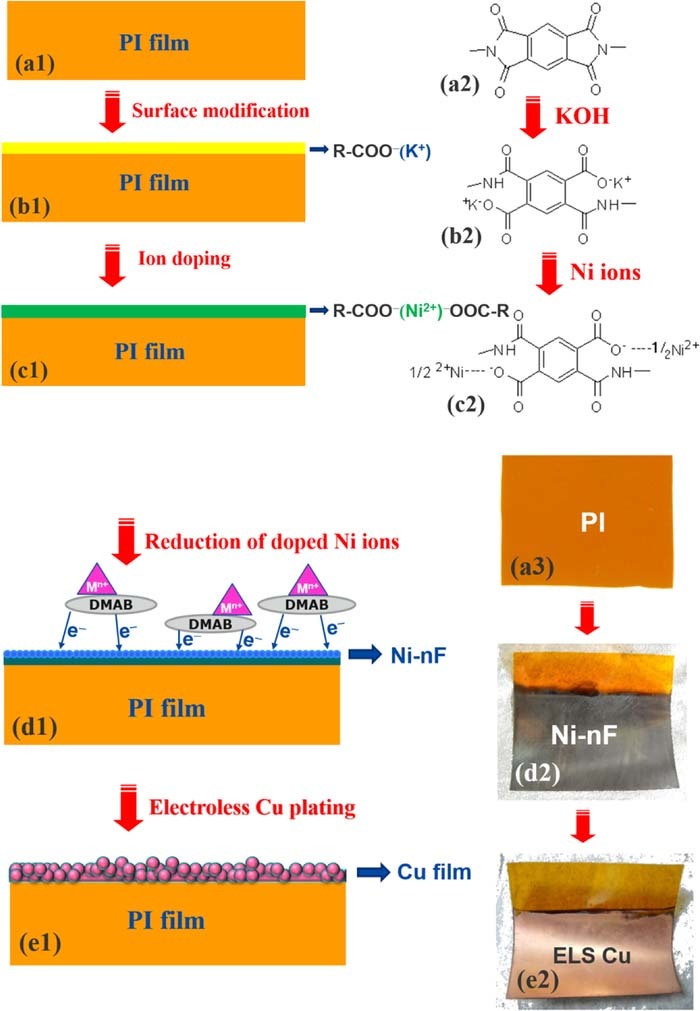
Figure 1. Schemes of process flow. (a) shows PI film and its corresponding molecular structure; (b) shows the surface modification of the PI using KOH solution and its corresponding molecular structure after KOH treatment; (c) shows ion exchange of K+ with Ni2+ and its corresponding molecular structure; (d) shows Ni-nF formation due to addition of few metallic ions (i.e., Mn+) into DMAB solution and its corresponding appearance; (e) shows electroless Cu film formation on the Ni-nF catalyst and its corresponding appearance.
Electroless deposition and characterization
The extent of PI hydrolysis by KOH solution was characterized using a Fourier transform infrared spectrometer (FTIR) (Varian 640-IR) with an attenuated total reflection (ATR) attachment. The element analyses of the chemically modified PI film were measured using an X-ray photoelectron spectrometer (XPS) (Ulvac-PHI, PHI 5000) with an Al Kα X-ray source (hυ = 1486.6 eV). The depth profiles of K+, Ni2+ ions and Ni-nFs in and on the modified PI film were obtained by argon ion bombardment in the spectrometer. The etching rate of the argon ion bombardment was around 24.1 nm min−1. The emission intensity was then converted to an atomic percentage (%).
The electroless copper deposition solution was composed of 0.04M CuSO4, 0.051M C6H5Na3O7, 3.8mM NiSO4, 0.17M NaH2PO2, 0.485M H3BO3 and 0.5 ppm thiourea. Its pH values was 7 and temperature was 40°C.
The surface morphologies and cross-sections of the samples were observed using field emission scanning electron microscope (FE-SEM, JEOL, JSM-7401F) and transmission electron microscope (TEM, JEOL JEM-1400 Electron Microscope), respectively. For cross-sectional TEM observation, the samples were sectioned into ca. 100-nm-thick slices with the conventional microtome technique using a diamond knife.
Results and Discussion
Figure 1 illustrates the process flow of the PI metallization. First of all, the surface of the PI was treated by KOH solution to open the imide ring of the PI and to form carboxyl group, producing a layer of poly(amic acid) (PAA),62–64 as illustrated in Figs. 1a, 1b. Following that, the KOH-modified PI was transferred in NiSO4 solution to implement ion exchange reaction of K+ with Ni2+. After the ion exchange reaction, the PAA contained a lot of Ni2+ ions because of its carboxyl groups, as illustrated in Fig. 1c.
To force the dispersed Ni2+ ions in the PAA to form a layer of Ni-nF on the surface of the PAA rather than to form nickel nanoparticles (NiNPs) and disperse in the PAA,60,65 a trace of metallic ions, such as Ag+, Cu2+ and Pd2+, were added in the reducer solution. These metal ions are able to catalyze the reducer to immediately release electrons (see Fig. S1) and reduce the Ni2+ ions on the PAA surface to Ni atoms and to extend to be a Ni-nF on the PAA surface, as illustrated in Fig. 1d. The rapid redox reaction was caused by Ni2+ reduction and DMAB oxidation, which leads to two positive effects. One is to form a steep concentration gradient of Ni2+ ion in the PAA, which enhances the diffusion rate of the Ni2+ ions toward the PAA surface. According to the Fick's law of diffusion as follows,
![Equation ([1])](https://content.cld.iop.org/journals/1945-7111/166/15/D843/revision1/d0001.gif)
where J is the flux of Ni2+ ions, DAB is the diffusivity and the diffusion flux is proportional to the concentration gradient (i.e., dC/dx). It is a dynamic state. The higher the concentration gradient is, the larger the diffusion flux will be. The concentration gradient can be approximately estimated from Fig. 2. They are (a) 0.25, (b) 0.477, (c) 0.48, (d) 0.42 intensity/cm. Obviously, Ag+ exhibits the best performance.

Figure 2. Depth Ni profile analyses of XPS. The profile indicates that after Ni2+ ions reduction, Ni2+ ions are rapidly reduced to nickel atoms and aggregate toward the surface of the PAA. Ag+, Cu2+ and Pd2+ ions can effectively facilitate the doped Ni2+ ions to be reduced and aggregate toward the PAA surface. Fig. 2a shows that more residual Ni2+ ions in the PAA, which shows that no Ag+, Cu2+, and Pd2+ ion, no nickel reduction facility effect and no aggregation effect. The two arrows indicate that the first arrow indicates rapid nickel ions reduction, the second arrow indicates concentration gradient effect to facilitate Ni2+ to diffuse toward the PAA surface. The position of the two arrows are indicated in Fig. 9.
The other is to block DMAB diffusion into the PAA, which results in NiNPs in the PAA. The NiNPs that were buried in the PAA have no contribution to the following electroless copper deposition. Instead, they may cause a loose Ni-nF because most of Ni atoms stay in the PAA rather than on the PAA surface, as illustrated in Fig. 1d.
The final step was to transfer the PI with the Ni-nF in an electroless copper solution for copper film formation, as illustrated in Fig. 1e. Commonly, the reducer used for electroless copper deposition is formaldehyde because the corresponding catalyst is palladium. Herein, the catalyst is Ni-nF, hence the reducer used for the electroless copper deposition is sodium hypophosphite (NaH2PO2). Otherwise, it is difficult to initiate the electroless copper deposition at a pH value of 7. Without the Ni-nF as a barrier layer for copper atom diffusion,60 the electroless copper layer would gradually disappear on the PI surface, as confirmed in Fig. S2. It significantly demonstrates that the PI film becomes semi-transparent after three days, if the catalyst film is Cu-nF rather than Ni-nF. The results show that copper atoms diffuse into the PI film and well disperse in the PI film.
Surface modification and characterization of PI and Ni-nF
To form a layer of PAA on the PI, the PI was immersed in a KOH solution. Figure 3a shows the FTIR patterns of a pristine PI film. Several typical absorption peaks were observed at 1775 cm−1 (imide C=O, asymmetric stretch), 1720 cm−1 (imide C=O, symmetric stretch), 1500 cm−1 (benzene ring, C=C stretch), 1370 cm−1 (imide C–N–C, ring stretch), and 1235 cm−1 (aromatic ether, Ar–O–Ar stretch).63,66–68 The FTIR pattern shown in Fig. 3a is in agreement with the result shown in Fig. 4a, indicating that only three elements, carbon, oxygen and nitrogen, were revealed by XPS.
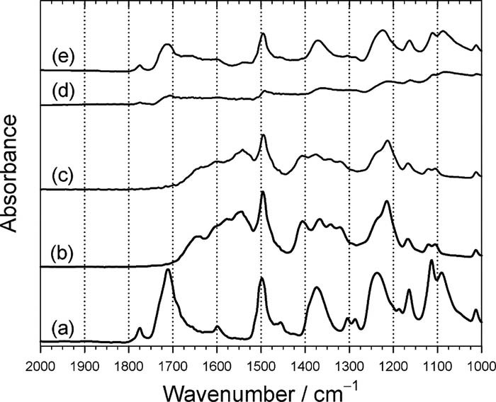
Figure 3. ATR-FTIR patterns of PI films and chemically modified PI films. (a) pristine PI film; (b) after hydrolysis reaction in KOH solution at 50°C for 5 min.; (c) after ion exchange of K+ with Ni2+ at 50°C for 5 min.; (d) after immersion in DMAB solution at 50°C for 10 min; (e) after annealing in N2 atmosphere at 350°C for 30 min.
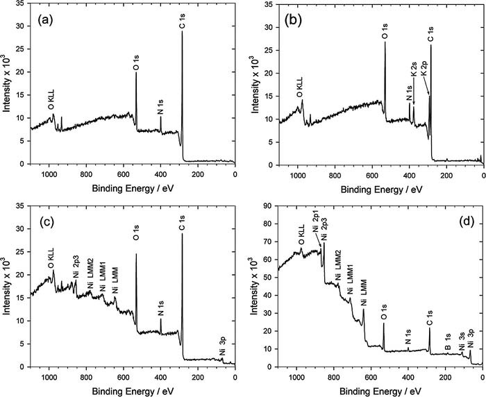
Figure 4. XPS analyses of PI. (a) pristine PI, (b) after immersion in KOH solution, (c) after immersion in NiSO4 solution, (d) after immersion in DMAB solution.
After the PI was immersed in the KOH solution for surface hydrolysis reaction, the absorbance peaks at 1775 cm−1, 1720 cm−1, and 1370 cm−1 disappeared, but the bands at 1500 cm−1 and 1235 cm−1 remained. On the other hand, several new absorbance peaks appeared at 1640 cm−1 (amide, N–H stretch), 1600 cm−1 (carboxylate salt, asymmetric stretch), 1545 cm−1 (amide, N–H bend), 1410 cm−1 (carboxylate salt, symmetric stretch), and 1220 cm−1 (carboxylic acid, C–O), as confirmed by the spectrum shown in Fig. 3b. This result indicates that a layer of poly(amic acid) (PAA) was formed due to immersion in the KOH solution.63,66–68 Of course, the signals of K+ ion was also obtained by XPS, as shown in Fig. 4b, which means that the imide ring on the PI surface was opened and R-COO−K+ was formed. Following the ion exchange reaction of K+ ion with Ni2+ ion, the FTIR pattern shown in Fig. 3c is the same as Fig. 3b. However, its XPS pattern significantly shows that the K+ signal disappears and Ni2+ signal appears, as shown in Fig. 4c, indicating that the doped K+ ions in the PAA layer were completely replaced by Ni2+ ions.
After the Ni2+-doped PI was immersed in the DMAB solution, the doped Ni2+ ions in the PAA were chemically reduced by DMAB to form Ni atoms. Hence, the signal intensity of Fig. 3d becomes weak because IR is difficult to tunnel through the Ni-nF. In the meantime, a chemical shift of nickel element occurred, as shown in Fig. 4d, implying that they are not nickel ions but nickel atoms. The performance of the ion exchange between the K+ and Ni2+ was confirmed by the depth profile analyses of XPS, as shown in Fig. 5. Obviously, element K [see curve (d)] completely disappeared instead of Ni element [see curve (e)]. In addition, the curve (e) shows that the distribution of Ni element is uniform in the PAA.
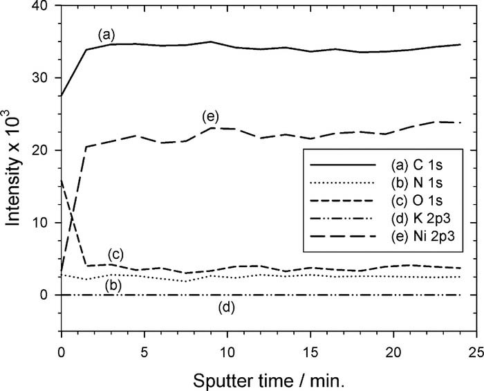
Figure 5. Depth profile analyses of elements using XPS. Obviously, after ion exchange, K+ ion completely disappeared and, oppositely, Ni2+ ions uniformly distributed in the PAA layer. It confirmed that there is no Ni2+ concentration gradient but uniform Ni2+ concentration profile in the PAA.
To further confirm this, XPS patterns of nickel element with high resolution were carried out and shown in Fig. 6. Obviously, no nickel metal was detected but nickel ion69,70 only before reduction reaction using DMAB, as shown in Fig. 6a. After reduction treatment in the DMAB solution, metallic nickel was detected combined with nickel ion, as shown in Fig. 6b. The results show that the doped nickel ions in the PAA were indeed chemically reduced to nickel atoms.70–72 As to the nickel ions shown in Fig. 6b, two possible reasons can explain it. The first possible reason is nickel oxidation in air with moisture after reduction reaction; the second possible reason may be attributed to that some of the doped nickel ions were not chemically reduced by DMAB.69–72 According to the relative signal intensities of curves (a) and (b), the nickel ions of curve (b) should be attributed to oxidation reaction with moisture because the doped nickel ions are buried in the PAA, which results in weak intensities, as shown in Fig. 6a.
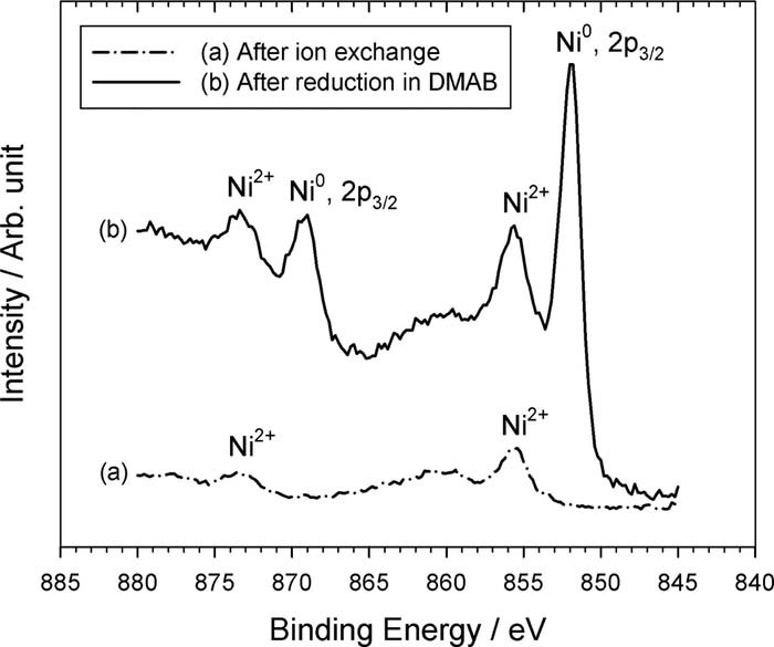
Figure 6. XPS analyses of PI. (a) after ion exchange reaction of K+ with Ni2+, (b) after immersion in DMAB solution.
Effect of metallic ion addition
A lot of papers have reported that the barrier layer, such as Ni-nF, is very important for PI metallization, because copper atoms easily diffuse into both PAA and PI film.1,73,74 Hence, before copper electroplating onto the PI film, a continuous and dense barrier film has to deposit onto the PI film first. Herein, we developed an approach that can form a layer of continuous and dense Ni-nF onto the PAA. The Ni-nF also possess catalytic activity for electroless copper deposition in order to enhance the conductivity of the metallized PI for the followed copper electroplating.
Figure 7 shows that the rapid electron release of DMAB in the presence of Ag+, Cu2+ and Pd2+ ions (see the LSV analyses shown in Fig. S1) to the nickel ions on the PAA surface, it can facilitate the upward diffusion rate of the doped nickel ions. This effect of rapid electron release of DMAB can be carried out by metallic ion addition (i.e., Ag+, Cu2+ and Pd2+) in the DMAB solution (see Fig. S1) to form a layer of dense Ni-nF on the PAA. Based on the grain density, Fig. 7A shows that the optimal concentration of AgNO3 is 1.06 ppm shown in Fig. 7A(e). Figure 7B shows that the optimal concentration of CuSO4 is 2.5 ppm shown in Fig. 7B(e). And Fig. 7C shows that the optimal concentration of PdCl2 is 0.84 ppm shown in Fig. 7C(e). These results are in agreement in the results shown in Fig. 2, which explain that the trend of electroless copper deposition rates with the salt concentration agree with the SEM morphologies, as shown in Fig. 7.
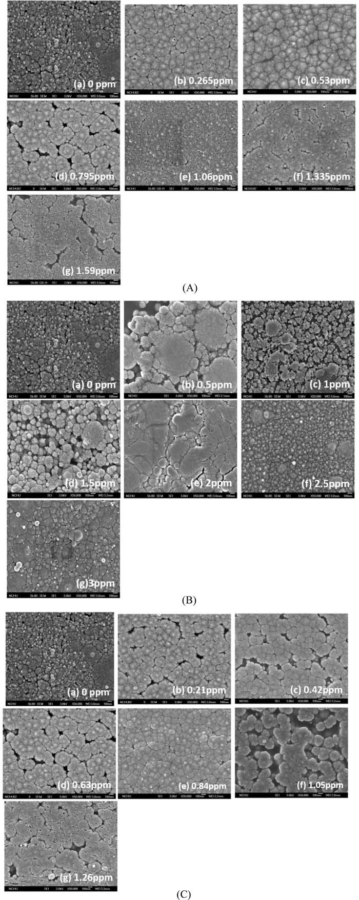
Figure 7. The SEM morphologies of Ni-nF on the PAA after reduction in the metallic ion-containing DMAB solutions. (A) AgNO3, (B) CuSO4, (C) PdCl2.
To further confirm that Ag, Cu and Pd ions can enhance DMAB oxidation and induce the doped Ni ions in the PAA prefer to aggregate on the PAA surface because of the rapid reduction of the surface Ni ions and correspondingly leading to a steep concentration gradient of Ni ion, HR-TEM was employed to image the PI cross-sections. Figure 8 shows the typical HR-TEM images, demonstrating that a lot of Ni nanoparticles were present in the PAA, as shown in Fig. 8a, because there was no metallic ion in the DMAB solution. The others, such as shown in Figs. 8b–8d, almost no Ni nanoparticle was present in the PAA but all Ni ions were reduced to Ni and aggregate to form a film on the PAA. The best performance appears in Fig. 8b, which means that Ag+ ion can effectively induce the doped Ni ions in the PAA to rapidly diffuse toward the PAA surface.
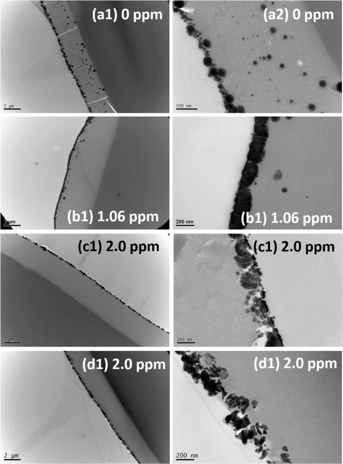
Figure 8. The HR-TEM images of Ni-nF/PAA/PI cross sections. (a) blank, (b) AgNO3, (c) CuSO4, (d) PdCl2.
Figure 2 further demonstrates that the reduced nickel ions do exhibit a steep concentration gradient in the PAA. Interestingly, two waveforms, indicated by the arrows, can be obviously obtained in the presence of Ag+ (see Fig. 2c), Cu2+ (see Fig. 2b) and Pd2+ (see Fig. 2d) compared with the case without those metallic ions (see Fig. 2a). The distance between the two waveforms (i.e., two peaks) shows that curve (b) ≅ curve (c) < curve (d) ≪ curve (a). The results indicate that Ag and Cu ions can rapid induce the doped Ni ion to diffuse toward the PAA surface, so that the aggregated Ni atoms distribution has a shorter distance compared with the case without metallic ion induction (i.e., curve (a)). Accordingly, the residual Ni ion of curve (a) was higher than the other curves, as shown in Fig. 2a.
A mechanism that can explain the effect of those salt addition in the DMAB solution is illustrated in Fig. 9 according to the results and Figs. 2 and 8. The scheme (A) shown in Fig. 9 describes the process of the Ni-nF formation without the salt addition. Finally, the Ni atoms will aggregate together to form nanoparticle on and in the PAA. On the other hand, the scheme (B) shown in Fig. 9 indicates the process of the Ni-nF formation with the salt addition. Finally, the Ni atoms will aggregate together to form the Ni-nF on the PAA because of the rapid electron release of DMAB catalyzed by those metallic ions. Therefore, there are almost no Ni nanoparticles but dense Ni-nF on the PAA, as illustrated in Fig. 9g. Of course, those metallic ions may be also chemically reduced by DMAB and incorporated into the Ni-nF. The issue was verified by secondary ion mass spectrometer (SIMS) analyses by adding 1.5 and 3.0 ppm salts in the DMAB solutions. As a result, Fig. S3 and S4 show that both cases cannot detect Ag, Cu and Pd elements, respectively. The results indicate that those metallic ions should only play the role of catalyst to facilitate DMAB to rapidly release electrons to reduce the doped Ni ions.
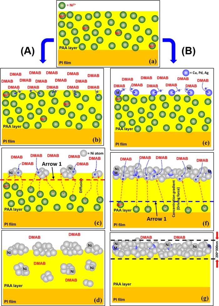
Figure 9. Scheme of effect of metallic ion addition in the DMAB solution. (b-c) without metallic ion addition, (e-g) with metallic ion addition. The red and blue dashed lines indicate the two arrows shown in Fig. 2, respectively.
To further confirm that DMAB is able to diffuse into the PAA and reduce the Ni ions in the PAA to be the Ni nanoparticles, looking like the scheme illustrated in Fig. 9d, a comparative experiment was carried out and shown in Fig. S5. Significantly, there were a lot of Ni nanoparticles in the PAA, as confirmed in Fig. S5(a, b), because the Cu2+ ion concentration was higher than 3 ppm. It may cause rapid DMAB oxidation and Cu2+ ion reduction. Hence, its final mode is similar to that of Fig. 9d, which means that DMAB is indeed able to diffuse into the PAA. On the other hand, the reducer was replaced by H2 gas, the mechanism would be similar to the case illustrated in Fig. 9g. There was no Ni nanoparticle in the PAA, instead, a Ni-nF was formed on the PAA surface, because H2 is able to rapidly release electron to the Ni ion on the PAA surface.
Characterization of electroless copper deposition
Figure 10 summarize the SEM images of after the electroless copper deposition and the corresponding salt concentration added in the DMAB solutions. The salt all has an optimal concentration for the electroless copper deposition rate. These optimal concentrations are exactly in agreement with the SEM morphologies shown in Fig. 7. Since the Ni-nF is a catalyst of the electroless copper deposition, its morphology certainly would influence its catalytic activity and corresponding deposition rate. Many small copper particles were observed in Figs. 10A, 10C. It can be attributed to that Ag and Pd are better catalysts than Cu for the electroless copper deposition. Therefore, these copper particles may be caused by a trace of randomly distributed Ag and Pd atoms. In fact, Fig. 11 confirms that the best Ni-nF catalyst is obtained from the Ag+ addition in DMAB, because its copper deposition rate was two times higher than those caused by Cu2+ and Pd2+ addition. Whatever, three metallic ions exhibit an optimal concentration that can lead to the maximum electroless copper deposition rate, which is in agreement with the results shown in Fig. 7, Fig. 10 and Fig. 11.
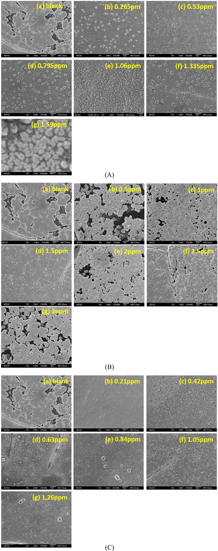
Figure 10. SEM images of electroless copper deposition. (A) AgNO3, (B) CuSO4, (C) PdCl2 addition in the DBAB solution.
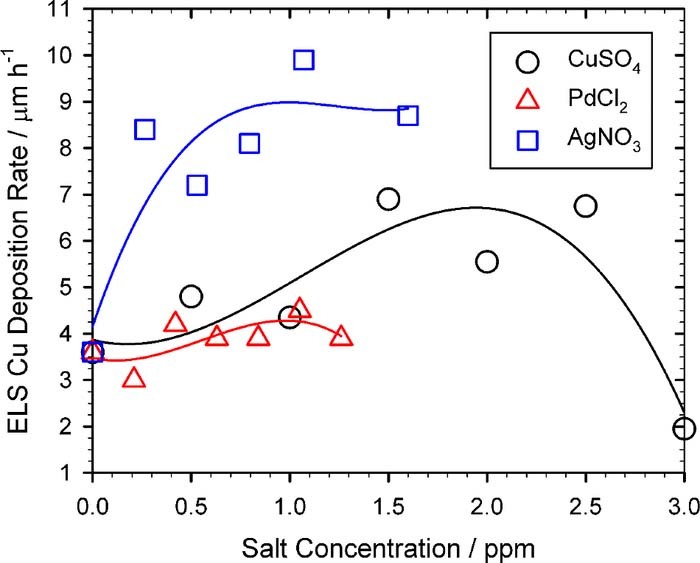
Figure 11. Electroless copper deposition rate at various salt concentration added in the DMAB solution. (□)AgNO3, (○)CuSO4, (Δ)PdCl2.
Conclusions
PI can be metallized by a layer of Ni film with a thickness of nm scale (i.e., Ni-nF), which acts as both copper barrier and catalyst of electroless copper deposition. The dense and continuous Ni-nFs are formed owing to the addition of a trace of Ag+, Cu2+ or Pd2+ ions in the DMAB solution, which cause the rapid electron release of DMAB to the doped Ni2+ on the PAA surface. The rapid reduction of the surface Ni2+ ions correspondingly lead to a steep Ni2+ ion concentration gradient within the PAA layer. As a result, the deeply doped Ni2+ ions can fast diffuse toward the PAA surface. Those added Ag+, Cu2+ and Pd2+ ions only play the role of catalyst for facilitating DMAB oxidation. They are not incorporated into the Ni-nF, which is confirmed by SIMS profile analyses. A reasonable scheme is proposed herein to explain the overall mechanism as mentioned above.
Acknowledgments
This research was funded by Ministry of Science and Technology of Taiwan (contract number: NSC 98-2218-E-007-001).
ORCID
Wei-Ping Dow 0000-0002-4870-6729