
Abstract
The TSV filling using the dialyl-amine and the Br− and Cl− halogen ions to a copper electrodeposition bath is reported. The TSV bottom acceleration and TSV outside inhibition have been measured by an electrochemical method using the rotating disk electrode and numerical computation of the fluid dynamics. A perfect TSV filling is achieved with 1 ppm P(DAMA[HBr]/SO2) + 1 ppm of Br− and the electrodeposited morphology is fine and bright. This shows acceleration at the lower rotation speeds of the rotating disk electrode and an inhibition at the higher speeds, if compared to 1 ppm P(DAMA[HCl]/SO2) + Cl−1 ppm. Br− 1 ppm shows a stronger inhibition at the higher rotation speeds, if compared to Cl−1 ppm. The addition of SPS in addition to Br− 1 ppm shows acceleration at the lower speeds. No voids formed at the higher current density of 3.5 mA/cm2 with SPS.

This is an open access article distributed under the terms of the Creative Commons Attribution 4.0 License (CC BY, http://creativecommons.org/licenses/by/4.0/), which permits unrestricted reuse of the work in any medium, provided the original work is properly cited.
Filled via stacking is an inevitable element of the buildup printed circuit boards in order to achieve high density interconnections.1,2 The vias are filled by the copper electrodeposition. Not only the built-up printed circuit boards, but also silicon chips are stacked with the through silicon via (TSV).3–5 For both the filled via and TSV, the vias are filled by the copper electrodeposition.2
Electrodeposition inhibition at the via outside and acceleration at the via bottom require desired current distributions to fill the vias without voids. The additives of an inhibitor, accelerator, leveler and halogen ion are necessary.6,7 The halogen ion, in most cases Cl−, interaction with the inhibitor and accelerator is extremely important for the additive role.8 The Cl− adsorbs at the copper electrodeposit and forms a cuprous electron bridge and binds with the polyethylene glycol (PEG). This Cl−, cuprous and PEG complex inhibit the copper electrodeposition.9,10 Completely different cyclic voltammetries (CV) have been reported for thiourea with and without Cl− by MS Kang.11–14 CV with only thiourea and without Cl− exhibits no hysteresis, and the CV is the same as no thiourea and Cl−. A large hysteresis occurs with thiourea and Cl−. Benzotriazole15,16 with saccharin17 and Cl− also exhibit a hysteresis.
For the acceleration, M. Tan showed that only with bis-3-sulfopropyl disulfide (SPS) does the potential show an inhibition, and by adding Cl− in addition to SPS, a drastic acceleration occurs.7 More recently, T. Hayashi and K. Kondo proposed an acceleration model with Cl−. Cl− forms an electron bridge and reduces cupric to cuprous.18 Cl− also reduces SPS to MPS(3-mercaptopropane sulfonic acid) and forms a complex of Cu(I)thiolate. This Cu(I)thiolate accumulates at the via bottom and preferentially accelerates the via bottom. T. Moffat showed that TSV rapidly fills with Poloxamine and several ten ppm Cl−.19 They suggested the adsorption of the Poloxamine and importance of hydrated water detachment. Instead of the halogen ion importance, only Cl− has been intensively investigated and very few studies exist about Br−. Y. Tsujimoto reported the PEG inhibition effect with Cl− and Br−.20
We focused on the dialyl-amine. M. Takeuchi reported that the Cl− counter ions adsorb on copper and inhibit the via outside electrodeposition.21,22 However, no study currently exists on the effect of halogen ions with the dialyl-amine. In this report, the TSV fillings and electrochemical measurements have been compared with two halogen ions of Cl− and also Br−.
Experimental
The basic bath consists of 130 × 103 ppm of CuSO4·5H2O and 200 × 103 ppm of H2SO4. Figure 1 shows the structure of the dialyl-amines. (a) the P(DAMA[HBr]/SO2) counter ion is Br−, and (b) the P(DAMA[HCl]/SO2) counter ion is Cl−. The dialyl-amine concentration is 1 ppm and 1 and 50 ppm of the halogen are added.
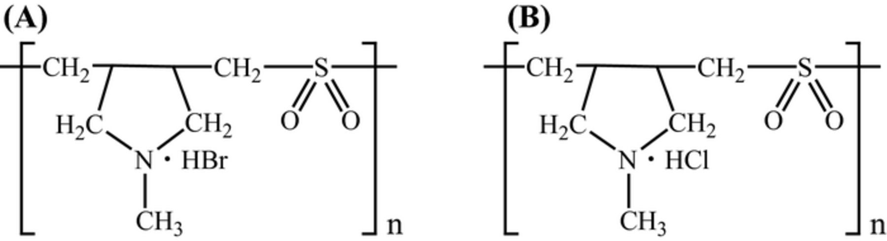
Figure 1. Structures of diallylmethylamine type copolymer additives. (A) P(DAMA[HBr]/SO2) (B) P(DAMA[HCl]/SO2).
The TSV via has a diameter of 5 μm and depth of 40 μm. The stirring speed of the magnetic stirrer is 1000 rpm, the current density is 3 mA/cm2 and the electrodeposition time is 60 min. The TSV substrates are imbedded in the resin and polished then observed by FE-SEM (Hitach, S-4300).
COMSOL Multiphysics software was used as a solver for the numerical computation of the fluid dynamics in order to compute the via inside velocity profiles. The basic equations are shown below.
Continuity equation
![Equation ([1])](https://content.cld.iop.org/journals/1945-7111/162/8/D397/revision1/jes_162_8_D397eqn1.jpg)
Navier-Stokes equation
![Equation ([2])](https://content.cld.iop.org/journals/1945-7111/162/8/D397/revision1/jes_162_8_D397eqn2.jpg)
An HZ-3000 from Hokuto Denko has been used for the electrochemical measurements. For the LSV, a rotating disk electrode has been used. The working electrode is platinum, the counter electrode is platinum wire and the reference electrode is a saturated calomel electrode. The electrode area of the rotating disk electrode is 0.196 cm2. The rotation speeds are 0, 10, 100 and 1000 rpm and the scan rate is 10 mV/s. For the galvanostatic potential measurement, the current density is 3 mA/cm2. The velocity effect on the potential with additives has been measured.
TSV filling
In addition to the dialyl-amine, we have added both 50 and 1 ppm halogen ions to the bath. Figure 2 shows the TSV filling cross sections and the electrodeposit morphology. (a) and (b) are P(DAMA[HBr]/SO2) 1 ppm + Br− 50 ppm and P(DAMA[HCl]/SO2) 1 ppm + Cl− 50 ppm, respectively. With the 50 ppm Br−, voids formed at the TSV bottom as illustrated by the arrow (a). With 50 ppm Cl−, no voids appeared and perfect TSV filling occurred(b). The morphology grain size with Br− is about 0.5 μm and finer crystal size (c). That with Cl− is course and 1 to 2 μm (d).
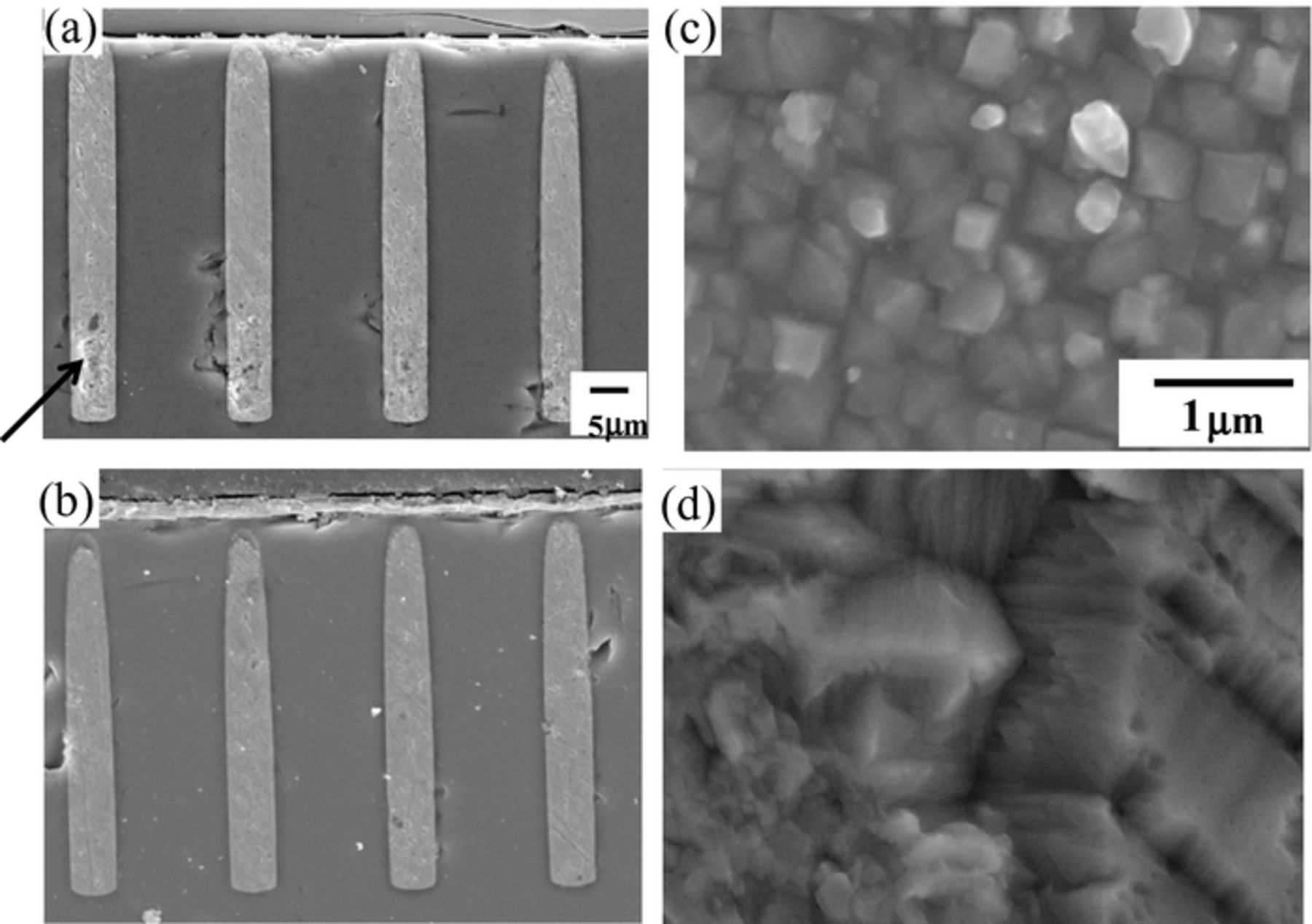
Figure 2. Cross section views and surface morphologies of TSV after electrodeposition at a high concentration of halide ions (50 ppm). (a) P(DAMA[HBr]/SO2) 1 ppm + Br− 50 ppm (b) P(DAMA[HCl]/SO2) 1 ppm + Cl− 50 ppm. (a), (b) Cross sections (c), (d) electrodeposited morphology.
The difference in the solubility product (Ksp) may cause the voids at the TSV bottom. The precipitation of the cuprous complex, CuBr, is more easy to form than CuCl. CuBr has a KspBr = 6.27 × 10⁻⁹, while CuCl has a KspCl = 1.20 × 10⁻⁷. The critical cuprous concentrations which start to precipitate CuBr and CuCl with 1 ppm dialyl-amine and 50 ppm halogen ions were determined. From [Br−] = 6.29 × 10⁻⁴ M and [Cl−] = 1.43 × 10⁻³ M, the critical cuprous concentrations, [Cu+]Br and [Cu+]Cl, are
![Equation ([3])](https://content.cld.iop.org/journals/1945-7111/162/8/D397/revision1/jes_162_8_D397eqn3.jpg)
![Equation ([4])](https://content.cld.iop.org/journals/1945-7111/162/8/D397/revision1/jes_162_8_D397eqn4.jpg)
Since the copper equilibrium constant is K = [Cu2+] / [Cu+] = 5.8 × 10⁻⁷ and cupric the concentration is [Cu2+] = 0.52 M, the bulk cuprous concentration is as follows
![Equation ([5])](https://content.cld.iop.org/journals/1945-7111/162/8/D397/revision1/jes_162_8_D397eqn5.jpg)
Hence, [Cu+]Br < [Cu+] < [Cu+]Cl, and CuBr precipitate first. This first precipitate of CuBr forms voids in the TSV cross section (arrow in Fig. 2a). In order to eliminate the voids, the halogen ion concentrations have been decreased from 50 ppm to 1 ppm.
Figure 3 shows the TSV cross sections with (a) P(DAMA[HBr]/SO2) 1 ppm + Br− 1 ppm and (b) P(DAMA[HCl]/SO2) 1 ppm + Cl− 1 ppm. The Br ion forms no voids and a perfect fill with the decreasing halogen ion concentration to 1 ppm (Fig. 3a). The Cl− ion forms huge voids (Fig. 3b). Furthermore, the Br− ion produces a finer and more uniform morphology if compared to that with Cl−.
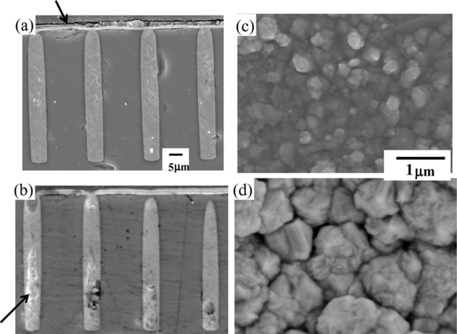
Figure 3. Cross sections and electrodeposited morphologies of TSV after electrodeposition at low concentration of halogen ions (1 ppm). (a) P(DAMA[HBr]/SO2) 1 ppm + Br− 1 ppm (b) P(DAMA[HCl]/SO2) 1 ppm + Cl− 1 ppm. (a), (b) Cross sections (c), (d) electrodeposited morphology.
Numerical computation of fluid dynamics
The velocity profiles around the 5 × 40 μm via are computed by a numerical computation of the fluid dynamics and are shown in Fig. 4. The X-axis is the distance from the via bottom and the y-axis is the velocity. Furthermore, the velocities of the rotating disk electrode with the radius of r = 0.75 and distance from the disk surface of Z = 108 μm are plotted for the rotating disk electrode rotation speeds of 0, 10, 100 and 1000 rpm. The velocity at via the bottom corresponds to 0 rpm. of rotating disk electrode, 31 μm from the bottom to 10 rpm and 50 μm to 100 rpm and 148 μm to 1000 rpm. To summarize, 0 and 10 rpm are the 5 × 40 μm via inside and 100 and 1000 rpm are the via outside. A velocity peak at 20 μm is due to the via inside eddy flow.
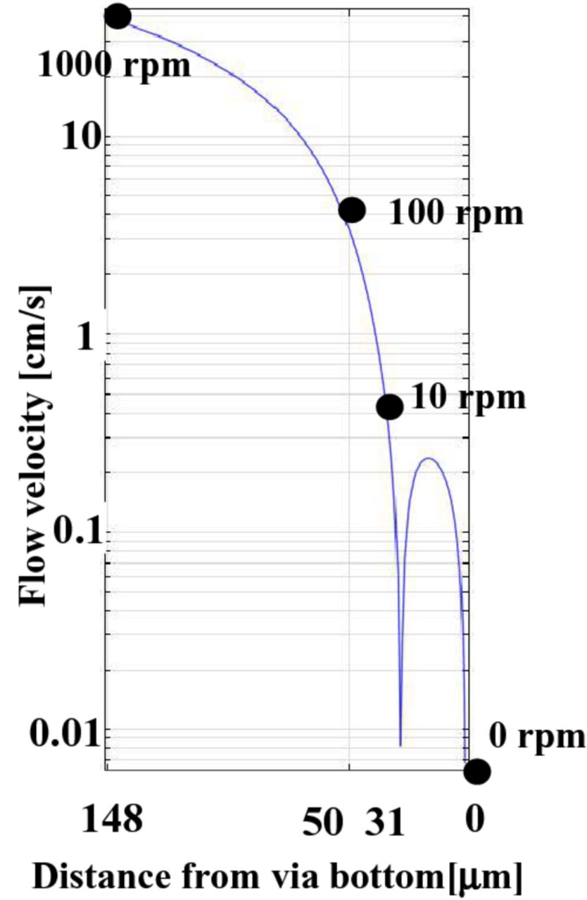
Figure 4. The flow velocity simulation results inside and outside of the via.
Electrochemical measurements
Linear sweep voltammetry (LSV) and constant-current electrolysis have been conducted. The LSV results are shown in Fig. 5. (a) is with 1 ppm P(DAMA[HBr]/SO2) + Br−1 ppm and (b) is with 1 ppm P(DAMA[HCl]/SO2) + Cl−1 ppm. The X-axis is the potential and the y-axis is the current density. The rotations of the rotating disk electrode are 0,10,100 and 1000 rpm. The strengths of additive inhibition have been compared by comparing the potentials at the current density rapid increase. The potentials have been swept from 0 to negative. The potentials of rapid increase in the current density are listed in Table I. The Br− potential for 0 rpm is −49 mV and 10 rpm is −44 mV. The Cl− potential for 0 rpm is −105 mV and 10 rpm is −69 mV. Br− shows more positive potentials at 0 and 10 rpms whose velocities corresponds to the via inside. The Br− potential for 100 rpm is −162 mV and for 1000 rpm is −212 mV. The Cl− potential for 100 rpm is −140 mV and for 1000 rpm is −165 mV. Br− shows more negative potentials at 100 and 1000 rpms whose velocities corresponds to the via outside. The Br− shows more acceleration at the via inside and inhibition at the via outside, if compared to Cl−. These electrochemical measurements correspond to the via cross sections. In Fig. 3a with Br−, the via outside thickness is thin (Fig. 3a, arrow) and no voids and perfect via filling are obtained. However, with Cl−, huge voids form (Fig. 3b, arrow).
Table I. The potentials of rapid increase in the current density.
| 0 rpm | 10 rpm | 100 rpm | 1000 rpm | |
|---|---|---|---|---|
| Br [mV] | −49 | −44 | −162 | −212 |
| Cl [mV] | −105 | −69 | −140 | −165 |
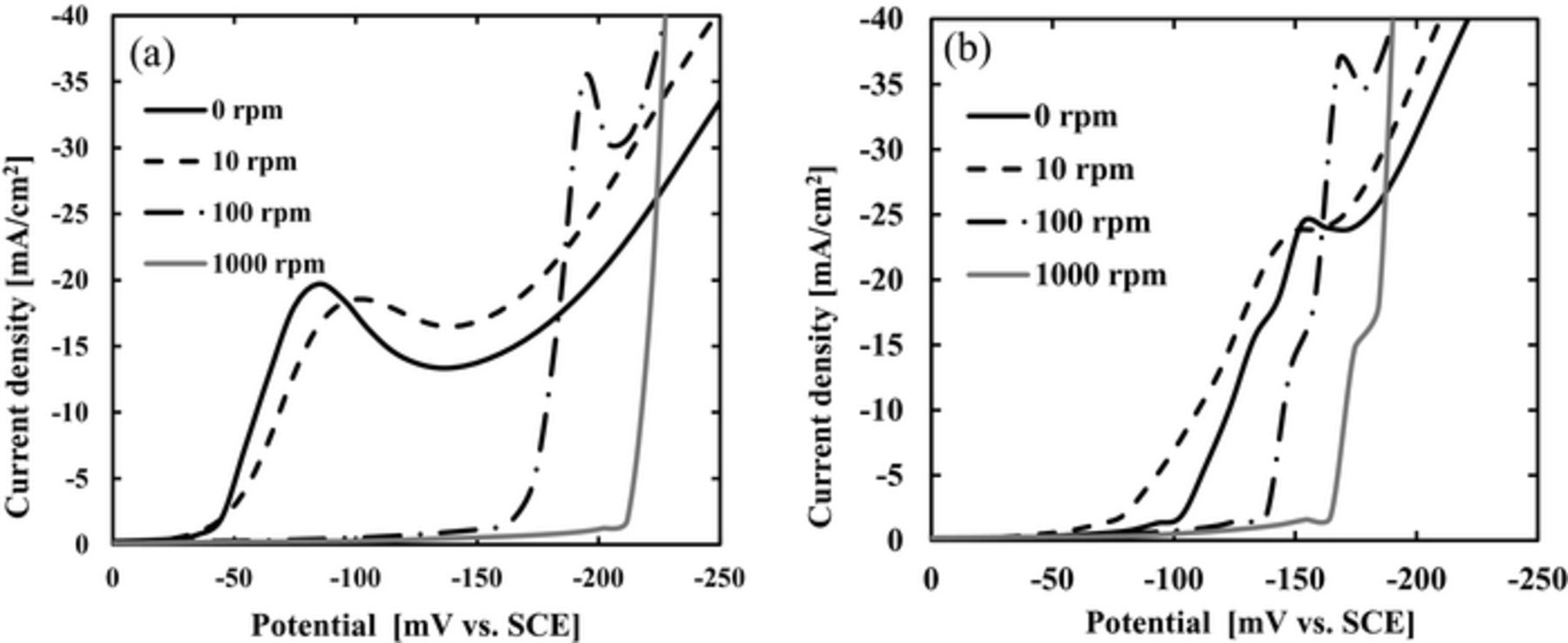
Figure 5. Results of LSV measurement using rotating disk electrode at 0, 10, 100, 1000 rpm. (a) P(DAMA[HBr]/SO2) 1 ppm + Br− 1 ppm, (b) P(DAMA[HCl]/SO2) 1 ppm + Cl− 1 ppm.
Fig. 6 shows the galvanostatic potential measurement at different rotating disk electrode rotation speeds. The additives are P(DAMA[HBr]/SO2)1 ppm + Br−1 ppm and P(DAMA[HCl]/SO2)1 ppm + Cl−1 ppm. The X-axis is the rotation speed and the y-axis is the potential at 3 mA/cm2. For the lower rotation speeds of 3 to 20 rpm, the Br− and Cl− show almost no difference in the potentials. However, at the higher rotation speeds of 100 to 1000 rpm, Br− shows more negative potentials, or inhibition. This inhibition dependence on rotation speed may be due to the concentration boundary layer.23,24 The via outside higher rotation region shows inhibition by adding Br−, when compared to Cl−.
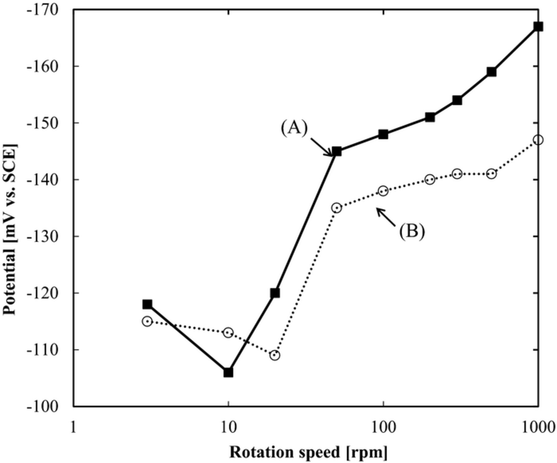
Figure 6. The relation of rotating speed and potential based on galvanostatic measurement. (A) P(DAMA[HBr]/SO2) 1 ppm + Br− 1 ppm (B) P(DAMA[HCl]/SO2) 1 ppm + Cl− 1 ppm.
Via bottom acceleration by SPS additive
The Br− strongly inhibits the via outside (Fig. 6). The SPS is known as a via bottom accelerating additive, thus the SPS effect was tested. With or without SPS, the relation of the rotating speed and the potential with galvanostatic measurement has been measured. Figure 7 shows the results. (A) is P(DAMA[HBr]/SO2) 1 ppm + Br− 1 ppm and (B) P(DAMA[HBr]/SO2) 1 ppm + Br− 1 ppm + SPS 2 ppm The potential is the same at 3 rpm. For the lower rotation speeds of 10 to 100 rpm with SPS, the potential is positive and an acceleration have been observed. For the higher rotation speeds of 200 to 1000 rpm the potentials are almost the same with a slight inhibition by the SPS. These relations of the rotating speed and potential from the galvanostatic measurements indicate the possibility of a high speed TSV filling with at the lower rotation speeds of 10 to 100 rpm when using SPS.
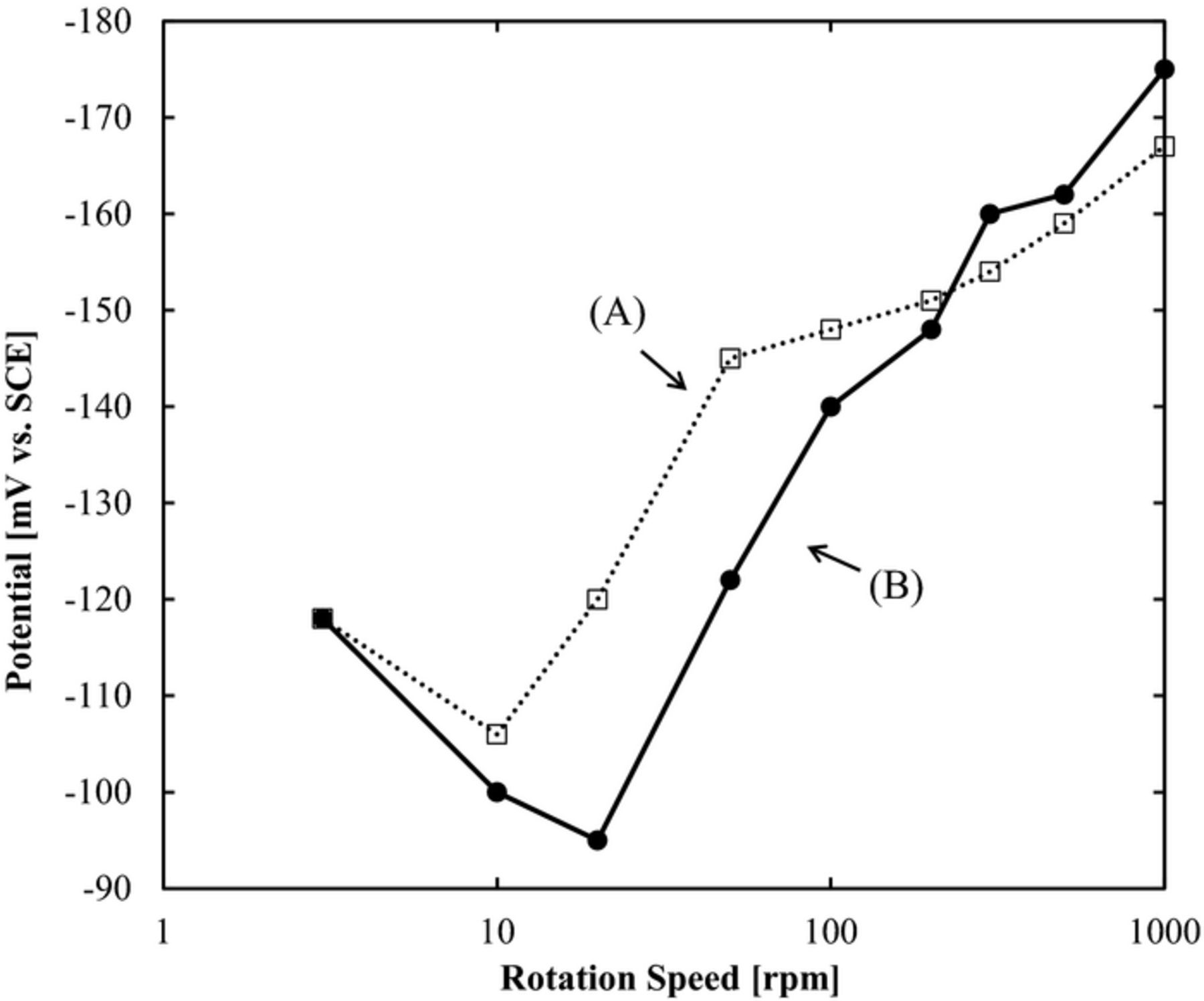
Figure 7. The relation of rotating speed and potential based on galvanostatic measurement with or without SPS. (A) P(DAMA[HBr]/SO2) 1 ppm + Br− 1 ppm (B) P(DAMA[HBr]/SO2) 1 ppm + Br− 1 ppm + SPS 2 ppm.
Figure 8 shows the TSV cross sections of (a) with 2ppm SPS and (b) without SPS at 3.5 mA/cm2. No voids and perfect via filling has been achieved by adding 2 ppm SPS (Fig. 8a). However, huge voids formed without the SPS (Fig. 8b, arrow). By adding SPS to the Br− ion bath, we have achieved a high speed TSV filling.
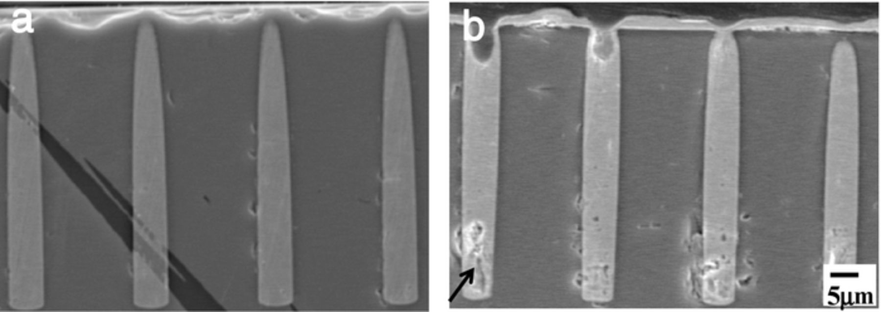
Figure 8. TSV cross sections at high current density (3.5 mA/cm2) with or without SPS. (a) P(DAMA[HBr]/SO2) 1 ppm + Br− 1 ppm + SPS 2 ppm (b) P(DAMA[HBr]/SO2) 1 ppm + Br− 1 ppm.
Conclusions
This report describes the TSV filling when the dialyl-amine and the Br− and Cl− halogen ions are added to the bath. The TSV bottom acceleration and TSV outside inhibition have been measured by an electrochemical method using a rotation disk electrode and numerical computation of the fluid dynamics.
- (1)The Br− and Cl− halogen ions effects have been initially tested at 1 and 50 ppm. With 50 ppm of Cl−, perfect via filling was achieved, however, the electrodeposited morphology is coarse. With 1 ppm of Cl−, voids form and the electrodeposited morphology is coarse. With 50 ppm of Br−, voids form and the electrodeposited morphology is coarse. A perfect TSV filling is achieved with 1 ppm of Br− and the electrodeposited morphology is fine and bright.
- (2)P(DAMA[HBr]/SO2) 1 ppm + Br−1 ppm shows an acceleration at the lower rotating disk electrode rotation speeds and shows an inhibition at the higher speeds when compared to P(DAMA[HCl]/SO2) 1 ppm + Cl−1 ppm.
- (3)Br− 1 ppm shows a stronger inhibition at the higher rotation speeds, when compared to Cl−1 ppm.
- (4)The addition of SPS in addition to Br− 1 ppm shows an acceleration at the lower speeds. No voids form at the higher current density with SPS.