
Abstract
A polyaniline dynamic electrode is prepared on titanium round plate through the galvanostatic polymerization synchronized with protonation and possesses the characteristics of conducting emeraldine salt state, granular surface structure, narrow bandgap energy, visible-light excitation. A photo-driving energy conversion system equipped with the polyaniline dynamic photoanode can degrade organic pollutants (i.e. reactive brilliant red x-3b dye) and concurrently generate hydrogen and electric flow. The hydrogen evolution amounts are 300.2 μmol and 163.5 μmol under ultraviolet light and visible irradiation, respectively. Based on its rapid doping/dedoping property, the polyaniline dynamic electrode is easily regenerated and almost recovered to the initial through re-doping with an acid. This work confirms the feasibility that polyaniline can be used alone as photocatalyst to construct a dynamic electrode, which is equipped in a photo-driving energy conversion system can convert organic pollutants into useful forms of energy (viz. hydrogen and electricity).
Export citation and abstract BibTeX RIS
TiO2 as a kind of low cost, abundance superior photostability and nontoxicity photocatalyst has been given a systematic and extensive study in many research fields including photo fuel cell, photoelectrochemical biosensor, photocatalytic degradation of pollutants, disinfection, reduction of CO2 and hydrogen evolution.1–6 However, it only absorbs wavelengths in the near UV region (λ < 400 nm), which is only about 3% of the solar spectrum and the visible light cannot be efficiently utilized.4 In order to efficiently utilize the main part of the solar spectrum in the photocatalytic reactions, many attempts have been made to seek and develop new materials. Conjugated polymers with extend π-conjugated electron systems have shown great promise, due to their high absorption coefficients in the visible part of the spectrum, high mobility of charge carriers, and excellent environmental stability.4,7,8 PANI, which is composed of aniline repeat units connected to form a backbone of alternating nitrogen atoms and benzene rings, can be classified as the fully reduced form (leucoemeraldine base, LB), the fully oxidized form (pernigraniline base, PNB), the half oxidized form (emeraldine base, EB), or the intermediate oxidation states (protoemeraldine and nigraniline) depending upon the degree of oxidation of the nitrogen atoms.9–12 EB, composed of equal numbers of benzenoid diamine and quinoid diamine repeat units, is the most useful state, because it can be transformed to the conducting emeraldine salt (ES) state through the protonation of the imine nitrogen. This protonation reaction causes a concomitant increase in the electrical conductivity of ca. 10 orders of magnitude.10,11 Another important feature is that PANI can absorb visible light to induce π−π∗ transition, transporting the excited electrons to the π∗-orbital.13,14 Due to that the lowest unoccupied molecular orbital (LUMO) of PANI and the conduction band (CB) of some wide band-gap semiconductors (i.e., TiO2) match well in energy level, PANI has been used to hybridize with metal oxide semiconductor to enhance their visible photocatalytic activity and increase the separation efficiency of photoinduced electron−hole pairs.15–17 Can PANI be directly used as a photocatalyst and what about the performance?
Given the interest in the improvement of electrodes, our group has already constructed a series of aqueous-film photoelectrodes such as rotating disk electrode, wedge-structure electrode, pyramid-surface electrode, slant-placed electrode, etc.18–23 The formation of micrometer-scale aqueous film on these photoelectrodes could reduce the light-path length in the solution and thus effectively minimize the light absorption of solution. In addition, several bismuth-based compounds loaded photoelectrodes were also synthesized to expect to harvest the satisfactory visible-light photocatalytic activity.24–28 Whether designing the macroscopic structure of photoelectrodes or exploring the new materials excited by visible light, our objective of a struggle is to realize the high efficient utilization of light energy and expand the applied spectral range to the whole solar spectra. Therefore, this paper aims to synthesize a highly conductive PANI dynamic electrode by one-step method (i.e. galvanostatic polymerization accompanied by protonation reaction) and convert organic contaminants into hydrogen energy and electric power under visible-light driven. The structure and morphology of the synthesized PANI on Ti substrate were characterized by field emission scanning electron microscopy (FESEM), X-ray diffraction (XRD), Fourier transform infrared spectra (FT-IR), and UV–vis diffuse reflectance spectra (UV-vis DRS) analysis. The photoelectrochemical properties were characterized by linear sweep voltammetry, photocurrent-time plots and incident-photon-to-charge conversion efficiency. In addition, a photo-driving energy conversion system (Fig. 1) was constructed with the PANI dynamic electrode as anode and reactive brilliant red x-3b (RBR) dye as a model fuel to investigate the multi-functional performance under UV and visible-light irradiation, that is the degradation of RBR dye accompanied by the synchronous production of hydrogen and electricity. The preparation parameters were optimized and the multi-functional performance obtained by polymer electrode were compared with that of TiO2 electrode. The reusability and regenerability were also investigated. A photoelectrochemical system was employed to verify the effectiveness of PANI dynamic electrode and preliminarily explore the possible influencing mechanism.
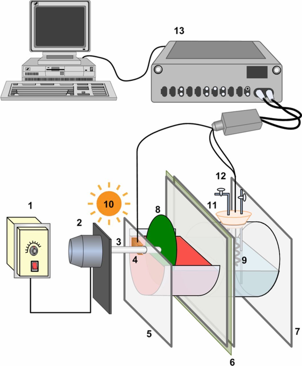
Figure 1. The construction of the photo-driving energy conversion system. 1. Speed controller; 2. Motor; 3. Ti rotation shaft; 4. Carbon brush; 5. Anode compartment; 6 proton exchange membrane; 7. Cathode compartment; 8. PANI dynamic electrode; 9. Pt cathode; 10. UV or visible light source; 11. Silica gel stopper; 12. Gas inlet/outlet port; 13. Autolab electrochemical workstation.
Experimental
Ti round plates (99.6% purity, 1.2 mm thickness, 100 mm diameter, Shanghai Hongtai Metal Production Co., Ltd.) were polished by abrasive papers with different size and then cleaned by ultrasonic washer in acetone ethanol and water, respectively. The synthesis of PANI was performed in a three-electrode electrochemical cell using Autolab potentiostat PGSTAT30 (Metrohm, Switzerland) with Ti plates as working electrode and counter electrode, respectively, and saturated calomel electrode (SCE) as reference electrode. The polymerization precursor was a mixed solution with 0.25 mol L−1 aniline and 0.1 mol L−1 H2SO4, which was stirred thoroughly and purged with continuous N2 flow of 80 cc min−1. Under the protection of N2, the galvanostatic density were investigated in the range of 0.4 ∼ 1.4 mA cm−2 electrode area (vs. SCE) and duration were from 5 to 50 min. After the electropolymerization, the as-prepared PANI covered Ti round plates were rinsed with water and air-dried at ambient conditions. In order to compare with the above polymer electrode, a TiO2 electrode was prepared on the same kind of Ti base plates through a sol-gel dip-coating method and the detailed procedure has been reported in our previous work.6,29,30
The obtained PANI was characterized by JSM7600F field emission scanning electron microscope (FESEM, JEOL Ltd., Japan), Nicolet 6700 Fourier transform infrared spectra spectrometer (FT-IR, Thermo Fisher Scientific, USA), D/max-2200/PC X-ray diffractometer (XRD, Rigaku, Japan), Lambda 750S UV-VIS-NIR spectrophotometer (UV-vis DRS, PerkinElmer, USA). The photoelectrochemical experiments were carried out in a three-electrode system using Autolab electrochemical workstation with a SCE as the reference, a platinum wire as the auxiliary electrode and as-prepared PANI covered Ti plate as working electrode in 0.5 mol L−1 Na2SO4 solution contained 80 mg L−1 RBR dye (commercial grade, Shanghai Jiaying Chemical Co., Ltd., China). An 11 W mercury lamp (Philips, 254 nm) and a 150 W xenon lamp (Shanghai Lansheng Co. Ltd., Shanghai, China) with a 400 nm cutoff filter were used as UV and visible light source, the light intensities were maintained constantly at 6 mW cm−2 and 17 mW cm−2, respectively. Incident-photon-to-charge conversion efficiency was measured by Zahner Zennium electrochemical workstation (IPCE, UATIL, Germany) using the three-electrode system with Ag/AgCl electrode as the reference at 1.0 V in 0.25 mol L−1 Na2SO4 solution.
The multi-functional performance was evaluated through a two-chamber energy conversion system. This system was acrylic glass materials and divided by a proton exchange membrane (Nepem-115, BEST Industry & Trade Co., Ltd., China) into two parts. As shown in Fig. 1, the anode compartment was exposed to the air, and the above prepared photo anodes were suspended by a Ti shaft to keep the bottom half to be immersed in the anolyte. The cathode compartment on the other side was tightly capped by a silicone stopper leaving holes for wire and gas inlet/outlet port, and a platinum wire was cathode. Anolyte was 2 mol L−1 NaOH solution contained 80 mg L−1 RBR, and catholyte was 1 mol L−1 H2SO4 solution. This system could work with many other substances but RBR dye was presently used as a model fuel. The potential difference existed between anode and cathode was supplied by chemical bias, which was established by the sacrificial agent (i.e. RBR in present design) and the acidity-alkalinity difference between the two electrolytes. 11 W mercury lamp (6 mW cm−2) and 150 W xenon lamp with a 400 nm cutoff filter (17 mW cm−2) were used as UV and visible light source, respectively, to irradiate anode. The photoanode was rotated at 90 rpm,6,29 driven by a motor (Outai Transmission Electromechanical Co. Ltd., Shanghai, China). Before beginning experiments, oxygen of the cathode compartment was completely removed by purging the chamber with pure N2 gas (99.9%) for 20 min. The hydrogen-evolution amount at the cathode was measured using a gas chromatographer (GC-14B, Shimadzu, Japan). Current flow was measured by a two electrodes system using Autolab electrochemical workstation with photoanode as working electrode, Pt cathode as auxiliary and reference electrode, and the applied voltage was set at 0 V. Unless otherwise stated, all experiments were repeated three times and the results were averaged.
A photoelectrochemical reactor analogous to the above energy conversion system has been reported in our previous paper.30 The electrolytes in the anode chamber and the cathode chamber were basically same except that the anolyte contained 80 mg L−1 RBR dye. H2SO4 (0.1 mol L−1), Na2SO4 (0.1 mol L−1), and NaOH (0.1 mol L−1) were employed to the photoelectrochemical reactor to investigate the performance of PANI dynamic electrode with various applied forward voltages (0.6, 0.8, 1.0, 1.2 and 1.4 V) under UV irradiation.
Results and Discussion
Characterization of the PANI
In this work, PANI was synthesized through the simultaneous reaction of the electropolymerization and the doping with protonic acids. The obtained PANI was green in color (Fig. 2 inset), which pointed out the conducting ES form. The surface structures of PANI characterized by FESEM are shown in Figs. 2a and 2b. The low-magnification image shows a layer of smooth film, which is incorporated with granular precipitates. Further increasing the magnification reveals that the granular precipitates are with a rough surface. The electrochemical polymerization of aniline mainly involved two stages.31,32 Firstly, aniline cation radicals adsorb primarily on the bare plate and give rise to smooth film composed of PANI macromolecules anchored to the substrates. Subsequently, the secondary nucleation of PANI occurs on the already grown PANI film, resulting in granular surface morphology with the incorporation of PANI precipitates into the continuous layer. The diameter of small granules composing the continuous layer is about 1 μm, leading to high surface areas and favoring good illumination utilization.
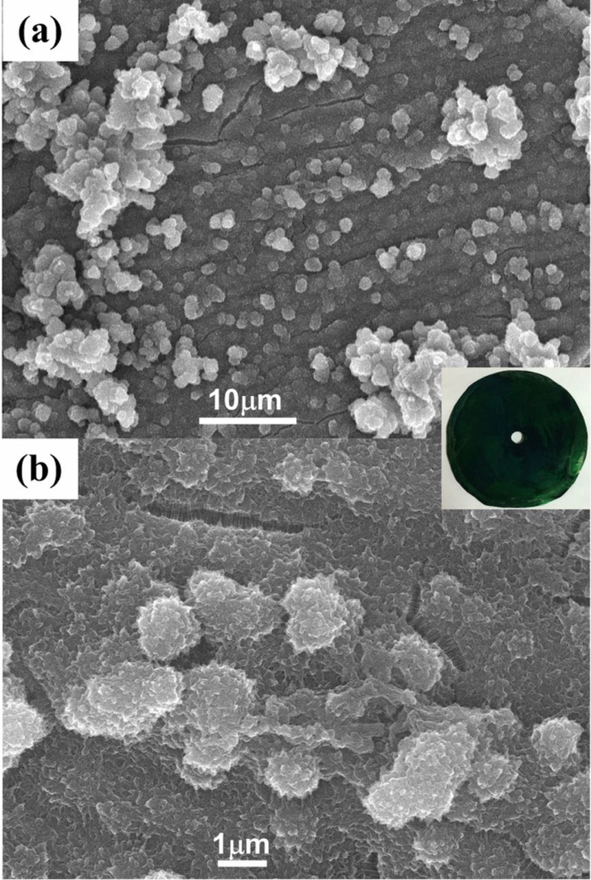
Figure 2. FESEM images of a top view of the PANI: low magnification (a) and high magnification (b); insert: the photograph of Ti round plate covered by PANI.
The FT-IR analysis was carried out to understand the chemical constitution of PANI. As seen in Fig. 3a, PANI has the characteristic peaks at 1560 cm−1 and 1478 cm−1 ascribed to the C=C stretching deformation of quinoid and benzene rings, respectively, 1298 cm−1 and 1240 cm−1 to the C-N and C=N stretching band of an aromatic amine, and 1110 cm−1 and 788 cm−1 to the in-plane and out of plane bending of C-H, respectively.15,33 The presence of the benzenoid and quinoid units is evidence of the emeraldine form of PANI. Fig. 3b illustrates that the amorphous nature of the sample is confirmed by the XRD spectrum, which shows broad and low intense peaks related to a poorly crystallized PANI. It has a primary characteristic peak at 25.2° attributed to the scattering from the periodicity perpendicular to PANI chains and the one at 20.3° to the alternating distance between layers of polymer chains.33,34 The UV−vis absorption spectra (Fig. 3c) indicates that PANI can absorb most light with a wavelength ranging from 200 to 800 nm, and the characteristic absorption peaks for PANI appears at 318 nm and 628 nm. The former is due to the π−π∗ transition between the benzoid units, and the latter is attributed to a charge-transfer excitation-like transition from the highest occupied energy level to the lowest unoccupied energy level.35,36 The gap is determined by extrapolating the linear portion of the curve (αhν)2 to hν axis and the transition is directly allowed, α being the optical absorption coefficient and hν the energy of the incident photon.34 The experimental absorption spectrum for PANI shows a bandgap of 1.63 eV. This was consistent with the previous reports,34,37,38 which is interpreted as excitations to the polaron band. The above results indicate that the as-prepared PANI can be excited by visible light due to its narrow bandgap energy.
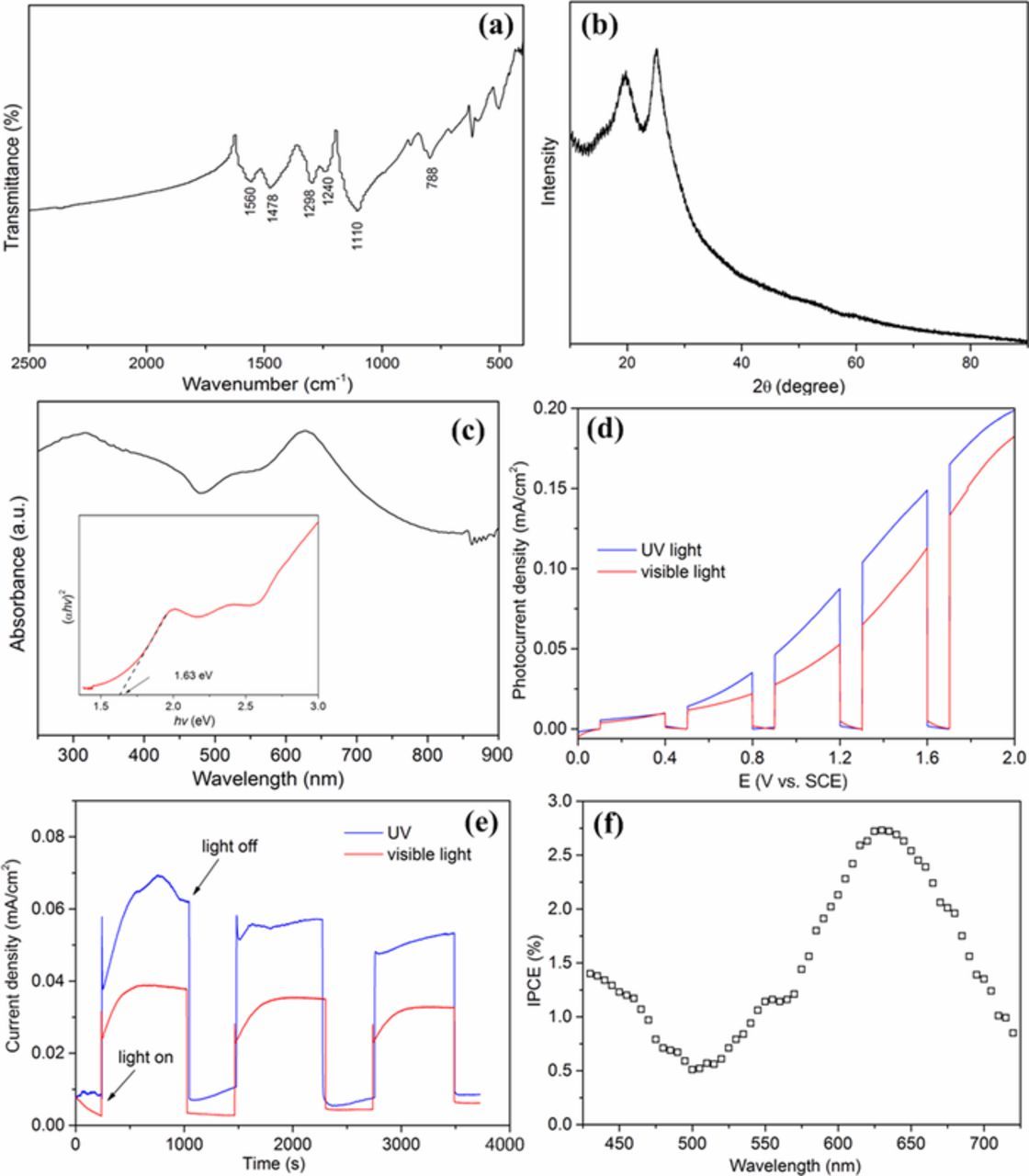
Figure 3. (a) FT-IR spectra, (b) XRD pattern and (c) UV-visible spectra of PANI (insert: the calculation diagram of the band gaps); (d) The chopped current-potential plots in 0.5 mol L−1 Na2SO4 solution contained 80 mg L−1 RBR; (e) Current-time curves recorded from the two-electrode configuration including PANI covered Ti photoanode and Pt cathode; (f) IPCE value of PANI covered Ti electrode at different wavelength light irradiation.
The photo-generated electrons during the reaction under UV or visible light irradiation were detected by the chopped linear sweep voltammograms (LSV). The results are shown in Fig. 3d, the current with no illumination (dark current) was relatively low. When illuminated by UV or visible light, the photocurrent was significantly increased, and the current obtained by UV light was higher than that of visible-light irradiation. The photocurrent densities were all further increased with the increasing of applied voltage. This demonstrates that the PANI on Ti plate plays a role of photocatalyst and can be excited by visible light. The stability of the polymer electrode for durable application was investigated by recording the current-time curves for 60 min under UV and visible light, respectively (Fig. 3e). The total current generated was stable and gradually decreased with time, which resulted from the consumption of RBR, or the "fuel". It indicates that the PANI covered Ti plate electrode possess potential to be employed as an photoanode for the degradation of organic pollutants with simultaneous generation of electric power.
The incident-photon-to-current conversion efficiency (IPCE) experiment was used to measure the effectiveness in converting photon incident to photocurrent flowing, when using the PANI covered Ti plate as photoelectrode. The IPCE was defined as a function of wavelength by the equation (IPCE = 1240 I/λ Jlight ), where I, Jlight, λ represent the photocurrent density, the incident light power density and the wavelength of the incident light, respectively.39,40 The wavelength range was 430 nm∼720 nm (with a resolution, Δλ = 5 nm). Fig. 3f shows the IPCE of PANI covered Ti electrode with respect to the wavelength, in which the photocurrent response tendency is consistent with the UV−vis absorption spectra (Fig. 3c). The IPCE curve exhibited the lowest values at the wavelength of about 500 nm and the maximum value obtained at 630 nm was ∼2.75%, which is in line with a previous report.40 From the graph, it is confirmed that the absorption of photons takes place in the visible region, and the photocurrent action spectrum resembled well with the absorption spectrum of PANI indicating that photocurrent is generated by the electron transition in the excited PANI molecules.
Parameters optimization of the galvanostatic polymerization
Parameters optimization was performed according to the conditions described in Experimental section during 6 different current densities, i.e. 0.4, 0.6, 0.7, 0.8, 1.0 and 1.4 mA cm−2 electrode area (vs. SCE), and 6 different polymerization times, i.e. 5, 10, 20, 30, 40 and 50 min. The optimum current density and duration time were judged by the hydrogen-evolution performance of the constructed photo-driving energy conversion system under UV irradiation with above prepared PANI dynamic electrode as photoanode (Fig. 4). With the increase of current density and the prolongation of polymerization duration, the hydrogen-evolution accumulations all shown a trend of "increase first and then decrease" and the maximum amount was about 300 μmol during the experimental period. Due to the two-stage polymer formation process in the galvanostatic polymerization of PANI, reaction conditions (polymerization time and current density) affect the polymerization velocity and film formation, thus influencing the thickness, homogeneity and morphology of the polymer film on the electrode surface.36,40 Especially when the polymerization current density increased to 1.4 mA cm−2 (vs. SCE), the hydrogen-evolution amounts significantly decreased to 165 μmol, which may be caused by the formation of the completely oxidized state. In brief, the polymer electrodes synthesized under different conditions possess different photoactivities, which further manifest as the difference of hydrogen-evolution performance obtained in the energy conversion system. In this sense, the optimal polymerization parameters were 0.7 mA cm−2 electrode area (vs. SCE) and 40 min.
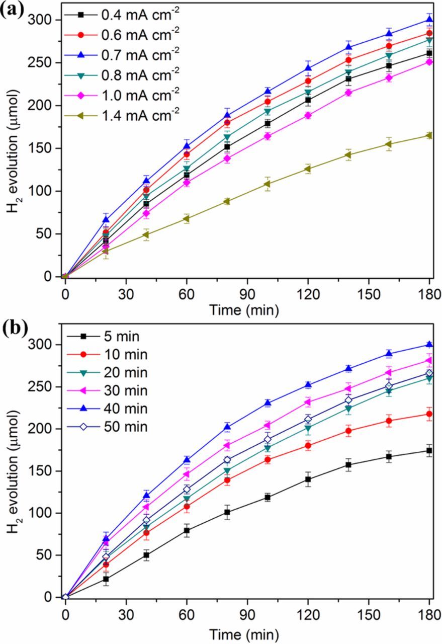
Figure 4. Effect of electropolymerization current density (a) and duration (b) on the photocatalytic hydrogen-evolution of PANI dynamic electrode.
The multi-functional performance of the energy conversion system
The photoactivity of the as-prepared polymer electrode was assessed under UV and visible light illumination by applying it to degrade model contaminated water of RBR aqueous solution whose initial concentration was 80 mg L−1. Figs. 5a and 5b were the real pictures of the photo-driving energy conversion system equipped with dynamic electrode under UV and visible light irradiation, respectively. In addition, a TiO2/Ti electrode prepared by a sol-gel and dip-coating method was used to compare and evaluate the photocatalytic performance of the PANI dynamic electrode. As shown in Fig. 5c, when UV light irradiated, the RBR dye was removed rapidly at the early stage of the reaction and about 90% RBR dye was degraded in 60 min for both the PANI electrode and TiO2 electrode. Besides, for the first 40 min, the RBR dye removal efficiency of PANI dynamic electrode was more than 10% better than that of TiO2/Ti electrode. Under visible light irradiation with λ>400 nm, the degradation efficiency increased gradually with time and about 40% of RBR was degraded by PANI dynamic electrode during the 180 min reaction. For comparison, the degradation by TiO2 electrode could be ignored due to that TiO2 can hardly be excited by visible light.
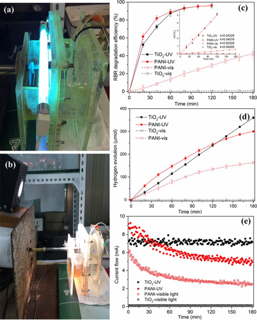
Figure 5. The real pictures of photo-driving energy conversion system under UV (a) and visible light irradiation (b); and the multi-functional performance equipped with PANI dynamic electrode or TiO2/Ti electrode: degradation efficiency of RBR (c) and its kinetic rate plots (inset), accumulation of hydrogen evolution (d), and current flow (e).
The photodegradation and adsorption of model pollutants can be described by the Langmuir-Hinshelwood kinetic model.41,42 When initial concentration of the reactant is very small, of around millimolar level, the reactions kinetic can be expressed as: −ln(C/C0) = kappt, where kapp is apparent rate constant (min−1), C0 is the initial concentration of dye and C is the concentration of dye after degradation for t min. The linear correlation of the plots of −ln(C/C0) versus time suggested that photocatalytic degradation of RBR by PANI dynamic electrode and TiO2/Ti electrode under different irradiation conditions basically obeyed the first-order kinetic model (Fig. 5c, inset). The apparent rate constants were 0.04076 and 0.04328 min−1 for PANI and TiO2 under UV irradiation, 0.00328 and 0.00005 min−1 for PANI and TiO2 under visible irradiation, respectively. These results suggest that compared with TiO2 electrode, thus prepared PANI dynamic electrode all represent a certain photocatalytic activity under UV and visible irradiation. On one side, under illumination, PANI absorb photons and generate electrons, while some positive carbon radicals in polymer chains are formed. These positive carbon radicals might be reduced by an electron from organic pollutants or water, or react with oxygen to generated active species (hydrogen radical, singlet/triplet oxygen) which are capable of degrading organic pollutants.43,44 On the other side, the prepared PANI with a narrow bandgap could be excited by visible light, and its granular surface structure not only enhanced the surface area, but also utilized the irradiation light more efficiently due to the multi-reflections on the surface.
In this system, the electrons generated by the photo-excitation of anode were transferred to the cathode surface for the hydrogen evolution through external circuit. Figs. 5d and 5e shown the hydrogen evolution and the current flow as a function of time, respectively. When using PANI dynamic photoanode, the hydrogen accumulation increased progressively with the reaction time but the hydrogen evolution rate decreased gradually. Correspondingly, the current flow decreased with time and ultimately became stable. Under visible light, the hydrogen accumulation quantity and current flow detected at 180 min were about 163.5 μmol and 2.7 mA, respectively, which were about half of that produced under UV irradiation (300.2 μmol and 5.2 mA). These results show that the photo-driving energy conversion system equipped with PANI dynamic electrode possess dual environmental benefits: pollutant can be cleaned and light energy, especially visible-light energy, can be converted into hydrogen and/or electricity. For the TiO2 electrode, the accumulation of hydrogen increased linearly with time (360.1 μmol at 180 min) and the current flow detected was 7.9 mA and relatively stable irradiated by UV light, while almost no hydrogen and current flow was detected under visible light. As is known, the combination of TiO2 and UV irradiation possess a strong ability to completely and non-specifically mineralize these organic compounds, and thus the electric flow and the hydrogen generation rate remain relatively stable during the experimental period. Moreover, at the early stage of the reaction under UV illumination, the hydrogen evolution and current flow obtained by PANI dynamic electrode were all greater than that of TiO2 electrode, which were in accord with the result of degradation. When the removal efficiency reached above 90%, the generation of hydrogen and electric power were still detected. Because of its unique structural features, RBR dye shows different UV-visible absorption spectrograms affected by the acidity-alkalinity of solution (Fig. S1) and then will appear different mechanisms of photo-degradation accordingly. According to previous reports,29,45 RBR dye is characterized by the presence of one azo group (−N=N−), which is a lower energy bond and easily broken, i.e., the conjugation system is damaged and the RBR dye loses its color. Subsequently, the colorless intermediates contained the aromatic structures were generated and would be further degraded. As shown in Fig. S2, the characteristic peaks at 400–600 nm ascribed to the chromophoric group (−N=N−) of RBR were proved to be degraded firstly. With the experimental time prolonged, the peaks at 250–400 nm were decreased gradually. These results provided the preliminary evidence for the degradation mechanism of RBR dye, which was proved to be in accordance with literatures.29,45 Even if the initial concentration of RBR dye increased, the dual performance of system were not significantly improved when using PANI dynamic electrode (Fig. S3). In addition, we found that the performance of hydrogen evolution and electricity generation cannot be maintained with time, whether under UV or visible-light irradiation. The following experiments were performed to explore the possible reason.
Photocatalytic stability of PANI dynamic photoanode
To evaluate the photocatalytic stability of the prepared electrode, PANI dynamic photoanode was used in this system for several photocatalytic runs under UV irradiation, and each run lasted 180 min. After each run, the system was evacuated and the polymer electrode was rinsed with deionized water, dried in air and used for the subsequent run. The results in Fig. 6a shown that the performance of hydrogen evolution markedly decreased with the increasing number of cycles, from 300.2 μmol to 79.3 μmol. After use, the change of the color on the PANI dynamic electrode was observed from green to purple-brown (Fig. 6c). The possible interpretation is that the anode electrolyte contains NaOH to establish a chemical bias and the PANI dynamic electrode is remained in contact with this alkaline electrolyte, which may caused the structural change during the reaction process because of its simple nonredox doping/dedoping chemistry based on acid/base reactions.9,10,46 While as for PANI, different oxidation and protonation states present different structures, properties, and colors, etc.31 According to the previous reports, re-doping with an acid could convert the PANI chains to the conductive emeraldine salt (ES) form.47,48 In order to verify this, we immersed the purple-brown polymer electrode in a 1 mol L−1 H2SO4 solution again for at least 1 h. After the re-doping process, the color of PANI became green again (Fig. 6c) and the performance of PANI dynamic electrode was regenerated. Nine runs of photocatalytic degradation process were repeated to generate hydrogen and current flow. After each use, the PANI dynamic electrode was doped with H2SO4 solution. The results were shown in Fig. 6b, the hydrogen-evolution amounts in 180 min fluctuated between 300 μmol and 325 μmol. Similar hydrogen accumulation efficiency at the same time interval during the repeated process preliminarily confirmed the above inference, that was the dedoping of PANI in the photocatalytic reaction process caused the hydrogen-evolution performance decline. While the re-doping of PANI dynamic electrode after reaction could make the photocatalytic performance be easily regenerated and almost recovered to the initial.
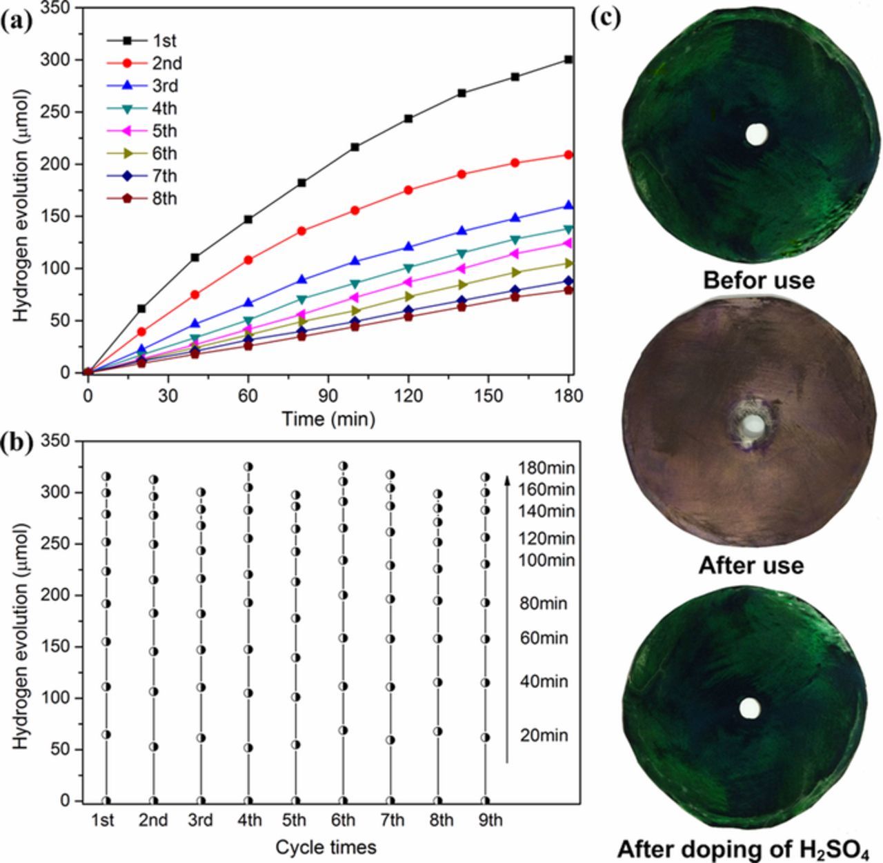
Figure 6. Reusability (a) and reproducibility (b) of PANI dynamic electrode; (c) photographs of PANI electrode before use, after use and after re-doping with H2SO4.
The application in photoelectrochemical reactor
Whether the constructed energy conversion system or the photoelectrochemical reactor, electrons generated in the anode compartment were transferred by potential difference to the cathode surface and reacted with protons to generate hydrogen. The required potential difference between anode and cathode could be supplied by chemical bias or a small electrical bias. As for photoelectrochemical reactor, if the applied electrical bias is too high, the electrolysis of water will occur to release hydrogen rapidly, which may inhibit the photocatalytic degradation of organic wastes in anode compartment. At the same time, in order to examine the PANI dynamic electrode life under different voltage conditions, a series of applied forward biases were added to the anodic potential with 0.1 mol L−1 Na2SO4 as electrolyte solution. As shown in Fig. 7a, under UV illumination, the accumulation amounts of hydrogen were nearly linear increasing with time and the hydrogen evolution rates increased gradually from 0.262 μmol min−1 to 0.771 μmol min−1 with the increase of applied biases from 0.6 V to 1.4 V. These results shown that the increase of voltage did not have adverse effects on the life and performance of PANI dynamic electrode. Without UV irradiation, there was no hydrogen detected in cathode region even at 1.4 V, demonstrating that when the external potential was lower than 1.4 V, the potential only promoted the transfer of electrons and did not electrolyze water. As a consequence, the applied bias was set at 1.4 V for the subsequent experiment. Considering that in real wastewater, the electrolyte type is different and the electrolyte concentration is relatively low. We investigated the effect of three types of electrolyte with low concentration and the results were shown in Fig. 7b. According to the principle of photoelectrochemical hydrogen evolution,30,49 there are two factors at work: one is the concentration of H+ in the catholyte, and the other is the number of electrons released through photocatalytic oxidation and transferred from anode region. In this sense, it was understandable that the hydrogen evolution rate obtained in H2SO4 solution was 1.206 μmol min−1 and much higher than that of Na2SO4 solution (0.771 μmol min−1). Nevertheless, when using NaOH as electrolyte, the hydrogen-evolution performance was further enhanced to 1.530 μmol min−1. This is owing to that the alkaline condition is propitious to the degradation of RBR and the formation of hydroxyl radicals, which may more effectively oxidize and degrade the aimed substrates.29,30,50 It is worth noting that regardless of what electrolyte type, the hydrogen-evolution performance could be maintained at a stable level with duration time and there was no variation observed in the color of PANI dynamic photoanode after use. Above results shown that alkaline solutions with a lower concentration would not cause the dedoping of PANI and the performance decrease of dynamic electrode. As for the PANI dynamic electrode, the existence of hydroxyl ions was all-important for photocatalytic degradation and hydrogen evolution.
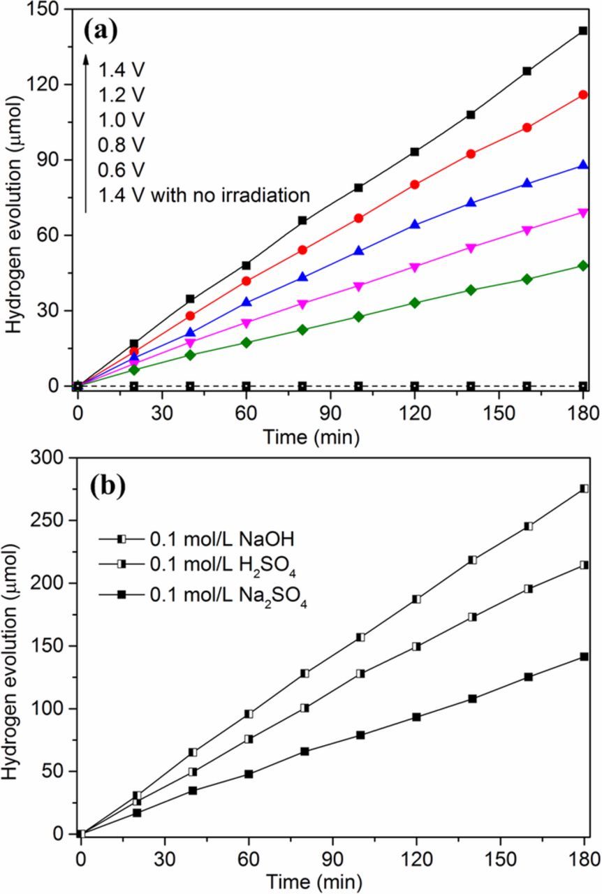
Figure 7. Effects of applied bias (a) and electrolyte type (b) on the hydrogen evolution in photoelectrochemical reactor.
Conclusions
This work synthesized a PANI dynamic electrode with the characteristics of conducting ES state, granular surface structure, narrow bandgap energy, visible-light excitation. A photo-driving energy conversion system equipped with the PANI dynamic photoanode could degrade organic pollutants (i.e. RBR dye) and concurrently generate hydrogen and electric flow. The hydrogen evolution amounts were 300.2 μmol and 163.5 μmol under UV and visible irradiation, respectively. Due to its nonredox doping/dedoping characteristic, PANI dynamic electrode could be easily regenerated through re-doping with an acid and the hydrogen-evolution amounts of the regenerated electrode fluctuated between 300 μmol and 325 μmol. The hydroxyl ions with low concentration benefited the photocatalytic degradation of RBR dye and would not wreak havoc in the ES state structure and the performance of PANI dynamic electrode. In conclusion, this paper shown that PANI possessed the ability to be used alone as the photocatalyst and could convert organic pollutants into hydrogen energy and electric power upon photo irradiation. Even so, the improvements of the PANI electrode will be the subject of follow-on work and the further exploration about the specific photocatalytic reaction mechanism will be reported in separate papers.
Acknowledgments
This work was supported by the Natural Science Foundation of China (Project No. 21806090 and 21607103) and Funds of Shandong "Double Tops" Program (SYL2017XTTD15).
ORCID
Tiantian Tang 0000-0001-6016-4339